Journal Paper
1
Independent Assessment and Benchmarking of
2
no/low cost Finite Element Analysis Software for
3
Linear Static Structural Analysis
4
Mr Saien Rugdeo 1, Dr Clinton Pierre Bemont 1* and Mr Jean-François Philippe Pitot de la
5
Beaujardiere 1
6
1 Discipline of Mechanical Engineering, University of KwaZulu-Natal
7
* Correspondence: [email protected]; Tel.: +27-83-289-9881
8
Academic Editor: name
9
Received: date; Accepted: date; Published: date
10
This work assesses no and low cost FEA software. The work is most relevant for businesses or
11
individuals who are not able to afford the industry standard proprietary FEA packages; this
12
paper might aid them in selecting a lower cost alternative while maintaining a level of
13
confidence in the results. The investigation was undertaken for both linear and nonlinear static
14
structural analyses using isotropic material models, but due to the volume of content, only the
15
findings for linear static modelling are presented here.
16
Abstract: The aim of this work was to determine if the development of low-cost or no-cost finite
17
element analysis (FEA) software has advanced to the point where it can be used in place of trusted
18
commercial FEA packages for linear static structural analyses using isotropic material models.
19
Nonlinear structural analysis will be covered in a separate paper. Several suitable packages were
20
identified, these underwent a process of systematic elimination when they were unable to meet the
21
minimum imposed qualitative criteria. Three packages were chosen to be subjected to performance
22
benchmarking, namely: Code_Aster/Salome Meca; Mecway and Z88 Aurora. SimScale, a
23
browser-based analysis package was included as well because it met all the baseline criteria and
24
has the potential to offer a completely cloud-based approach to computer aided engineering,
25
potentially reshaping the way an engineering business views its operational capabilities. This
26
paper presents the test cases and simulation results for packages that fall under the linear static
27
structural analysis type.
28
Keywords: Open source; FEA; finite element analysis; linear static structural; Code_Aster; Salome
29
Meca; Mecway; SimScale; Z88, CAE
30
31
1. Introduction
32
The rapid increase of computational power over the past few decades has been a catalyst for change
33
in various industries. Software developers are able to take advantage of increasing computational
34
power and can create numerical modelling packages capable of dealing with a progressively larger
35
range of physical problems [1]. Consequently, increasing confidence is being placed in the results of
36
computational simulations [2].
37
The increasing acceptance of computational analysis results has created a problem. Software
38
developers have been pushed to improve their packages capabilities, which subsequently increases
39
costs. The cost of trusted proprietary numerical modelling packages is generally significant and, in
40
some cases, exorbitant. These packages are typically used by large companies or research
41
institutions with the resources to acquire them. The inability to readily acquire these numerical
42
modelling software packages puts small to medium sized design and manufacturing companies at a
43
disadvantage, as it limits their operational capabilities. Fortunately, there have been a growing
44
number of small proprietary software developers as well as an active open source development
45
community, creating and improving relevant software packages in fields such as CFD and FEA.
46
These can potentially be used in place of the expensive commercial proprietary packages. This paper
47
concisely presents the findings from a master’s dissertation completed by the first author. The
48
research aimed to determine if the development of low-cost/no-cost software packages, specifically
49
in the field of FEA in computational structural mechanics (CSM), has advanced to the point where a
50
capable analyst can confidently use one of these packages in place of a globally trusted proprietary
51
FEA software package for linear and nonlinear static structural analyses using isotropic material
52
models. Due to the volume of content, the research has been split into two papers. This paper only
53
presents the findings for linear static analysis modelling; a future paper will present the findings
54
related to nonlinear static structural analysis problems.
55
2 The Impact of FEA on Industry
56
The advancement in capabilities of simulation software over the past two decades has significantly
57
changed the way in which product conceptualization and design is viewed. Looking specifically at
58
the advancement in FEA software, it has allowed for significant innovation and the development of
59
accurate design methods at drastically reduced cost [3].
60
With the increase in the capability and fidelity of commercial software, FEA has influenced a new
61
market trend in industry. The term “simulation-driven product development” is commonly used to
62
describe the integration of simulation software into the early design process and basing decisions on
63
simulation results [4].
64
Evidence to validate the above statement can be found in a relevant report titled “The 2013 State of
65
Simulation Design” [2]. The aim of the report was to answer the following question: “Are today’s
66
engineers making decisions based on simulations?” The findings of the report were based on survey
67
responses from 826 respondents from a wide range of industries worldwide. The majority of the
68
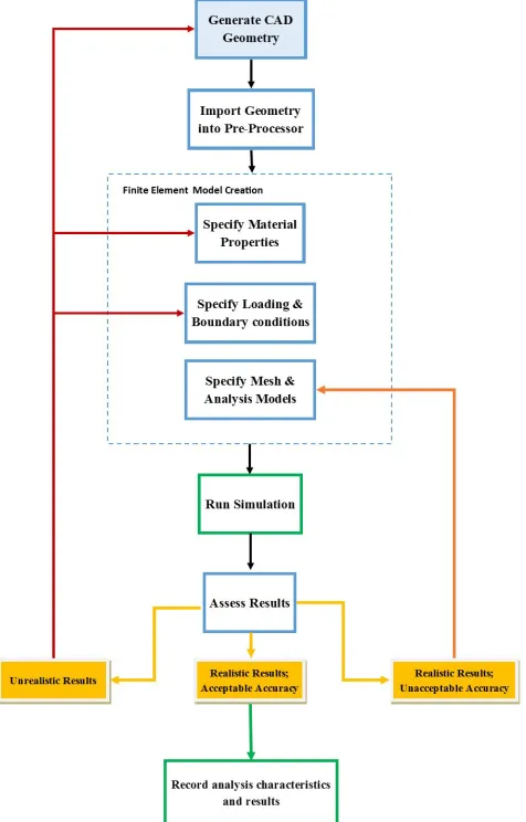
respondents were from the automotive, industrial equipment manufacture, aerospace and defence
69
industries [2]. The survey focused mainly on how respondents used simulation to drive decisions
70
during the concept design phase, as well as in the more detailed design phase.
71
There are many adverse effects caused by failed prototypes and concept designs. Many of these
72
waste time and resources and could potentially cause the termination of a design project. Key
73
business value findings showed that best-in-class manufacturers will need to hit roughly 86% of
74
their cost and release targets while releasing 1.6 fewer prototypes than competitors on average [5]. In
75
excess of 70% of respondents stated that simulation results are used to select or improve concept
76
designs [2]. When looking at the more detailed design phase, more than 75% of the respondents
77
stated that simulation is used to refine or select ideas. Through simulation based design refinements,
78
companies were able to better determine correct sizing and appropriate material selection, which in
79
turn drives production costs down. The results of the survey indicated that less than 10% of the
80
respondents within major engineering fields did not make use of any simulation during their design
81
process.
82
Simulation techniques such as FEA and CFD have become an industry standard. Taking these
83
figures into account, it is evident that the majority of industries are using computational simulations
84
to drive design and manufacture, therefore significant cost savings can be incurred by acquiring
85
capable no-cost/low-cost simulation software to replace existing high cost industry-standard
86
options, particularly for small to medium sized companies who may not perform as frequent
87
simulation, and for whom software costs likely make up a larger proportion of their expenses.
Looking at the implementation of no-cost/low-cost software in the context of a small business, it
89
would allow for previously unobtainable resources to become a part of regular operational
90
capabilities, likely making the business more competitive and relevant in the modern market.
91
3. Methodology
92
3.1 Software identification and selection
93
Research allowed for the identification of several low-cost/no-cost FEA software packages. Choosing
94
a limited number of no-cost/low-cost packages that pass certain baseline criteria before proceeding
95
to the performance benchmarking phase of the research aided in streamlining the entire process.
96
The basis of the chosen selection criteria was guided by anticipated industry requirements. It was
97
based on both research and on discussion and hands-on experience, with two of the authors
98
operating a small mechanical engineering consultancy previously utilising both industry standard
99
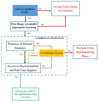
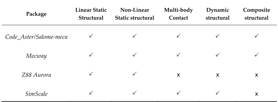
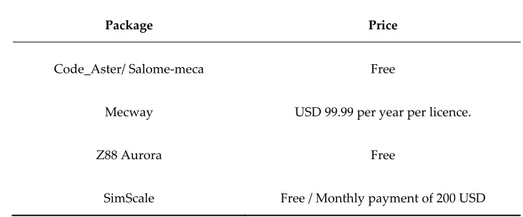
and free software. The selection procedure implemented is illustrated in Figure 3-1.
100
101
Figure Error! No text of specified style in document.-1. Package selection procedure
102
The inability to perform the required type of analysis immediately excluded a package from further
103
investigation. The price of the package and licencing approach was considered. If the package was
104
‘expensive’ (chosen to be greater than 500 USD per year as initial cost of purchase) or licenced such
105
that it prohibits the use of the package commercially, it was excluded. If a package passed the
106
aforementioned criteria, the presence of the internal modules were checked.
107
The lack of either a pre-processor or a post-processor did not immediately exclude the package. It
108
resulted in the package going into a consideration process. A judgement was made based on the
109
ability of the solver to accept various imported file formats as well as export post-processing file
110
formats from commercial packages as well as other low-cost/ no-cost packages. If a package was
deemed to be capable with respect to file type compatibility, the documentation and user support
112
was investigated. If it appeared that no user support was readily available then the package would
113
return to the consideration process. If it was deemed that the package was not user friendly (via
114
either the interface itself or documentation or support) as well as lacking a pre or post-processor, it
115
would be excluded from the following phase of the research.
116
The selection of two premium commercial packages was done for quantitative and qualitative
117
comparison between what is considered a premium package and the chosen no-cost/low-cost
118
packages. The selection of commercial FEA software was based on software availability at the
119
University of KwaZulu-Natal.
120
3.2 Review and Selection of Benchmarking Test Cases
121
Appropriate benchmark tests cases were selected to be simulated within the chosen packages. This
122
process began by investigating the verification manuals of renowned, commercially available FEA
123
software packages. This revealed that the leading software developers verify their codes through a
124
benchmarking process that utilizes well-known analytical solutions as well as examples from trusted
125
benchmark publications. The benchmark publishers referenced were the National Agency for Finite
126
Element Methods and Standards (NAFEMS) and Société Française des Mécaniciens.
127
With this knowledge, a variety of test cases were selected that fell within the scope of this research.
128
Test cases were separated into analytical problems with known solutions and benchmark standards.
129
A final test case was based on experimental data from physical laboratory testing. This will be
130
discussed in a future paper discussing the nonlinear analysis testing.
131
Selection of the test cases was based on the test case falling within static structural analysis, the
132
problem geometry and loading conditions being easily repeatable, and the potential for the problem
133
to be readily tested and validated experimentally. The selected test cases are presented in section 5.
134
3.3 Solution of Test Cases Using Selected Software
135
The chosen packages were subjected to the selected test cases. The simulation process used for the
136
test cases can be seen in Figure 3-2. The result was analysed and classified within one of three result
137
categories.
138
The first category, “Realistic results, acceptable accuracy”, would see the solution exhibiting the
139
expected response to the loading and constraints, with the value of the solution strongly correlating
140
to expected values stipulated by the test case.
141
Research was conducted to determine what the industry accepted measure of ‘accuracy’ is. There is
142
no agreed upon value as it appears that ‘accuracy’ is very application-specific. Trusted discussion
143
forums show claims from industry analyst that inaccuracies up to 10% for linear static examples are
144
acceptable for certain applications. Others report that for some complex examples, such as analyses
145
involving material non-linearities or contact problems, errors may commonly be as high as 20% [6].
146
For the purpose of this research, accurate solutions must fall within 5% of the target solution. This
147
value is lower than what industry analysts suggest because the benchmarking analyses selected are
148
not considered highly complex and a capable FEA package should thus be able to readily generate
149
solutions with greater accuracy than for more complex systems.
150
The second category, “realistic results, unacceptable accuracy”, pertains to situations when the
151
solution exhibited the expected response but yielded a solution with unacceptable accuracy. This
152
would indicate that the boundary conditions were likely correctly implemented. To address the
153
inaccuracy in the solution, the mesh parameters or mathematical model used to solve the model
154
should be re-evaluated. This loop can be run until satisfactory results are obtained.
The third category, “unrealistic results”, pertains to situations where results generated do not exhibit
156
expected response to the loading conditions or yield grossly inaccurate numerical values. This
157
phenomenon could be attributed to various factors. In such cases it is advised to revisit the various
158
aspects of the model construction, as shown in Figure Error! No text of specified style in
159
document.-2 and verify that these aspects represent the physical system being modelled as closely as
160
possible. This loop can be run until satisfactory results are obtained.
161
162
Figure Error! No text of specified style in document.-2. Computational simulation process
163
This validation phase assessed the performance of the selected packages. Results for each test case
164
with each package were gathered and processed. The results were compared against expected
165
theoretical solutions so that a gauge of accuracy could be obtained.
166
4. Selected software
167
Using the selection procedure discussed in Section 3, three no-cost/low-cost packages were selected
168
to be investigated further. A no/low-cost web-based simulation platform was added to the selection.
169
• Code Aster is a freely available open source, Linux-based solver package commonly used in
170
civil and structural engineering. It is most commonly used through Salome Meca, which acts
171
as the GUI for pre and post-processing. It was developed by the French company, EDF and
172
the software and documentation was previously only maintained in French [7], but the
173
software is now available in English with poorly machine translated documentation
174
available. Salome Meca is a very compartmentalized application and requires users to load
separate modules in order to import and prepare geometry, create a suitable mesh and
176
finally to view the results. The actual computation of the finite element solution happens
177
through Code_Aster. The user must be well versed in the scripting language readable by the
178
Code_Aster solver. The user must be able to code the aster file so that the correct analysis
179
type, material models, loads and constraints are all incorporated. There is a significant
180
learning curve and it does prove quite complex to new users.
181
• Mecway is an inexpensive Windows-based package that allows users to solve various
182
engineering problems using the finite element method [8]. The user interface has many of
183
the characteristics found in trusted commercial packages. A single licence costs 99 USD per
184
year.
185
• Z88 is a free, cross platform package that can be used for the solution of various engineering
186
problems through numerical simulation by the finite element method. There are 2 versions
187
currently available. Z88 V14, an open source version lacking a pre-processor, and Z88
188
Aurora, a freeware version with built-in pre-processor [9].
189
• SimScale is a web-based simulation platform for the solution of certain physics problem
190
types through numerical methods. SimScale has the analysis capabilities to provide
191
solutions to 3-D problems only, in structural analysis, thermodynamics and heat transfer,
192
CFD, particle analysis, acoustics as well as coupled multiphysics problems. Lower
193
dimension problems are not currently solvable. A free account can be created which entitles
194
the user access to the full range of analysis capabilities. Paid users have access to priority
195
computing resources as well as a direct line of contact with SimScale consultants[10].
196
Table 4-1 through to Table 4-4 present various aspects of the investigated packages.
197
Table Error! No text of specified style in document.-1. Analysis capabilities
198
Package Linear Static
Structural
Non-Linear Static structural
Multi-body Contact
Dynamic structural
Composite structural
Code_Aster/Salome-meca
Mecway
Z88 Aurora x x x
SimScale x
199
Table Error! No text of specified style in document.-2. Operating systems
200
Package Linux MS Windows MAC OSX
Code_Aster/ Salome-meca x
Z88 Aurora
SimScale Does not depend on Operating system
201
Table Error! No text of specified style in document.-3. File type compatibility
202
Package Import Export
Code_Aster/ Salome-meca
Generated mesh files and CAD files of various formats.
Code_Aster generates a MED file which can be exported to Salome Meca or any other compatible post-processing software
Mecway
CAD geometry import: .iges, .step. Generated mesh files e.g.
Gmsh, NetGen.
Can export result files in VRML format to graphical processing tools to generate
contour plots.
Z88 Aurora
CAD geometry import capabilities
Generated mesh files.
Allows for FE structure data such as ANSYS, NASTRAN and ABAQUS files to
be exported.
SimScale CAD imports through .step files Result files can be exported to 3rd party
postprocessors eg Paraview.
203
Table Error! No text of specified style in document.-4. Pricing
204
Package Price
Code_Aster/ Salome-meca Free
Mecway USD 99.99 per year per licence.
Z88 Aurora Free
SimScale Free / Monthly payment of 200 USD
205
5. Results and Discussion of Linear Static Structural Analysis test cases
206
Several sources were initially considered and many potential test cases were identified. The
207
following cases were chosen from amongst the available possibilities as they would test a range of
208
analysis capabilities with respect to static structural analyses, with minimal repetition of model
209
types.
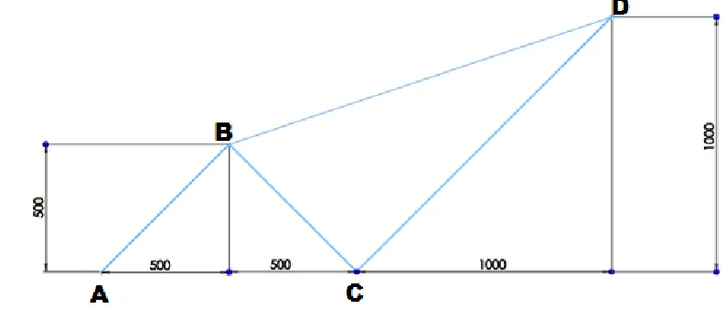
5.1 Point Load on an Articulated Truss
211
This test case was taken from an industry accepted standards publication [11]. This test is a 2-D
212
linear static analysis of 1D truss. Figure 5-1 presents the 1D line geometry for this test case.
213
Table Error! No text of specified style in document.-5 shows the information associated with this test
214
case.
215
Table Error! No text of specified style in document.-6 presents the target solutions for this test case as
216
given in test case.
217
218
Figure Error! No text of specified style in document.-3. Truss system geometry [11]
219
220
Table Error! No text of specified style in document.-5. Input parameters for truss analysis problem.
221
Material Properties E = 1.962 E+11 Pa
Geometrical Properties
Element Area (m2)
AB & BC 2 E-4
BD & CD 1 E-4
Boundary Conditions
Node Constraint/Load
A Zero X and Y displacement
B Zero X and Y displacement
D Force = 9810 N in -Y direction
222
Table Error! No text of specified style in document.-6. Target solutions for truss problem.
Node point Target Benchmark Value (m)
C X - displacement 0.26520 E-3
C Y - displacement 0.08839 E-3
D X - displacement 3.47900 E-3
D Y - displacement -5.60100 E-3
224
To successfully model this test case, the suggested approach was to import the geometry to the
225
pre-processor or create it within the pre-processor, and assign the two required truss element types
226
as applicable. The prescribed boundary conditions must be applied to the relevant nodes. Finally,
227
the post-processing module of the package must be able to represent the target solutions on an
228
appropriate plot.
229
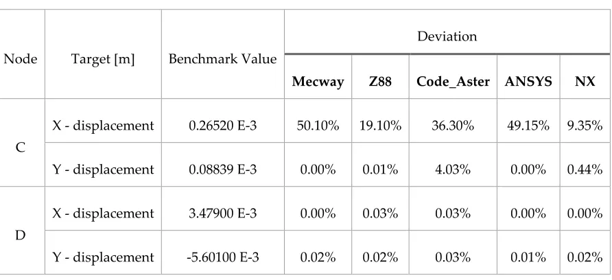
Simulation Results
230
Table Error! No text of specified style in document.-7 contains the results for this test case. Note that
231
results are presented for individual nodes.
232
Table Error! No text of specified style in document.-7. Results for Point Load on an Articulated
233
Truss Test Case
234
Node Target [m] Benchmark Value
Deviation
Mecway Z88 Code_Aster ANSYS NX
C
X - displacement 0.26520 E-3 50.10% 19.10% 36.30% 49.15% 9.35%
Y - displacement 0.08839 E-3 0.00% 0.01% 4.03% 0.00% 0.44%
D
X - displacement 3.47900 E-3 0.00% 0.03% 0.03% 0.00% 0.00%
Y - displacement -5.60100 E-3 0.02% 0.02% 0.03% 0.01% 0.02%
235
Note that SimScale is unable to perform analyses on 1-D geometry at this stage of its development.
236
The remaining packages were able to generate the model in the suggested approach and yield
237
appropriate displacement results through a graphical postprocessor. It is seen that the
238
no-cost/low-cost options as well as the commercial packages all yielded results with large deviations
239
from the target solutions for the X-direction displacement at Node C. Bearing in mind that the
240
benchmark target solutions are performed computationally, it might indicate thepossibility of an
241
inaccuracy in the target solution, but would not explain the difference in deviation from 9% to 50%.
All other results fell within an acceptable deviation. All employed packages dealt well with the
243
model generation and offered intuitive node-element creation tools.
244
245
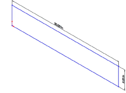
5.2 Thin Shell Wall in Pure Bending
246
This test case was taken from the engineering text, “Mechanical Engineering Design” [12]. This test
247
case is a 3-D linear static analysis which investigates the maximum deflection and stress in an edge
248
loaded wall, which is represented as a 2-D shell for analysis. Figure Error! No text of specified style
249
in document.-4 shows the geometry of the 2-D shell representation of the geometry. Table Error! No
250
text of specified style in document.-8 shows the information associated with this test case. Table
251
Error! No text of specified style in document.-9 presents the target solutions for this test case as given
252
in test case.
253
254
Figure Error! No text of specified style in document.-4. Wall geometry represented as a 2-D shell [12]
255
256
Table Error! No text of specified style in document.-8. Input parameters for wall problem.
257
Material Properties
E = 30 E-6 psi
ν = 0.03
Geometric Properties
Length = 30 in
Width = 5 in
Thickness = 0.1 in
Boundary Conditions
Zero displacement for edge situated at the origin
258
259
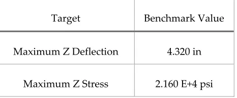
Table Error! No text of specified style in document.-9. Target solutions for wall problem.
260
Target Benchmark Value
Maximum Z Deflection 4.320 in
Maximum Z Stress 2.160 E+4 psi
To successfully model this test case, the suggested approach was to import a 2-D shell geometry into
261
the pre-processor of the package. An appropriate 2-D element must be used to mesh the geometry
262
and the stipulated material properties must be assigned. The pre-processor must be used to stipulate
263
the required boundary conditions. The post-processing module for the package should be used to
264
represent the target solutions on appropriate plots.
265
Simulation results
266
This test case was run several times, refining the mesh each time, while keeping other variables
267
constant. The results presented in Table Error! No text of specified style in document.-10 are those of
268
the result set with the finest mesh size of 0.15 in. Results tended towards greater accuracy with
269
decreasing mesh size.
270
271
Table Error! No text of specified style in document.-10. Results for Thin Shell Wall in Bending Test
272
Case
273
Point Target Benchmark Value
Deviation
Mecway Code_Aster ANSYS NX
Loaded Edge
Maximum Z
Deflection 4.320 [in] 1.64% 0.02% 0.02% 0.02%
Fixed Edge Maximum Z Stress 2.160 E+4 [psi] 5.69% 0.18% 0.18% 0.00%
SimScale is unable to perform analyses on 2-D bodies at this stage of its development. Z88 Aurora
274
was unable to produce a suitable 2-D mesh to discretize the geometry. Attempts were made to use a
275
3-D mesh to discretize the model, however a suitable mesh was not able to be generated in either
276
SimScale or Z88 Aurora. The remaining packages were able to yield results that fell within
277
acceptable accuracy, apart from the stress value yielded by Mecway.
278
279
This test case was taken from an industry accepted publication “The NAFEMS Standard
281
Benchmarks” [13]. This test case, labelled LE7 in the publication, is a linear static analysis of a
282
cylindrical pressure vessel with spherical end caps. Due to the geometrical symmetry of the model, it
283
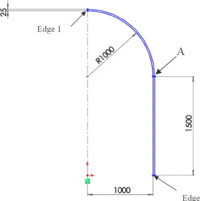
can be modelled as a 2-D axisymmetric surface.
284
Figure Error! No text of specified style in document.-5 below shows a 2-D axisymmetric
285
representation of the pressure vessel presented in millimetres
286
287
Figure Error! No text of specified style in document.-5. Axisymmetric representation of pressure
288
vessel [13]
289
290
Table Error! No text of specified style in document.-11. Input parameters for axisymmetric pressure
291
vessel test case.
292
Material Properties
E = 2100 MPa
ν = 0.3
Geometric Properties Axisymmetric 2-D Shell with given
dimensions
Boundary Conditions
Edge 1 – Zero X-Displacement
Edge 2 – Zero Y-Displacement
Uniform internal pressure = 1 MPa
293
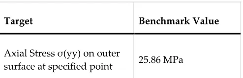
Table Error! No text of specified style in document.-12. Target solutions for axisymmetric pressure
294
vessel analysis problem
Target Benchmark Value
Axial Stress σ(yy) on outer
surface at specified point 25.86 MPa
296
To successfully analyse this test case, the suggested approach was to import the 2-D geometry into
297
the pre-processor. It would be ideal if the package had a dedicated 2-D axisymmetric analysis option
298
available. The pre-processor should be used to specify 2-D elements with the required material
299
properties assigned. The boundary conditions should be applied in a manner that correctly
300
represents the axisymmetry present. The target solution requires a specific directional stress and
301
hence the solver should be able to compute this stress value. Lastly, the post-processing module for
302
the package must be used to represent the target solution on an appropriate plot.
303
Simulation results
304
This test case was run several times, refining the mesh while keeping other variables constant. The
305
results presented in Table Error! No text of specified style in document.-13 are those of the result set
306
with the finest mesh size of 5mm. Results tended towards greater accuracy with decreasing mesh
307
size.
308
Table Error! No text of specified style in document.-13. Results for axisymmetric pressure vessel
309
analysis problem
310
Point Target Benchmark
Value
Deviation
Mecway Z88* Code_Aster SimScale* ANSYS NX
Prescribed outer surface
point
Axial Stress
σ(yy)
25.86 [MPa] 0.23% 4.41% 0.04% 2.39% 0.03% 0.54%
311
As mentioned before, SimScale was unable to perform analyses on 2-D bodies at this stage of its
312
development. Z88 Aurora was unable to produce a suitable 2-D mesh to discretize the geometry.
313
Attempts were made to use a 3-D quarter geometry model to analyse problem for both SimScale as
314
well as Z88 Aurora (*). In both cases a coarse mesh could be used to yield results, however the
315
software crashed when mesh refinement was attempted as the number of elements became
316
excessively high.
317
All packages were able to yield results of acceptable accuracy. Mecway, Code_Aster, ANSYS and
318
NX all possess dedicated axisymmetric analysis environments which assisted in streamlining the
319
model generation phase and in producing accurate results.
320
321
323
5.4 Internal Pressure on Thick-Walled Spherical Container
324
This test case was taken from an industry-accepted standards publication titled, “Guide de validation
325
des progiciels de calcul des structures” [11]. This test labelled SSLV 03/89 is a 3-D linear static analysis of
326
a thick-walled spherical vessel experiencing an internal pressure loading. Due to the geometrical
327
symmetry, the vessel can be modelled as a quarter sphere as seen in Figure Error! No text of
328
specified style in document.-6. Dimensions are presented in millimetres
329
330
331
Figure Error! No text of specified style in document.-6. Quarter sphere geometry [11]
332
333
Table Error! No text of specified style in document.-14. Given information for spherical pressure
334
vessel analysis problem
335
Material Properties
E = 200 MPa
ν = 0.30
Geometric Properties Quarter spherical geometry with
specified dimensions
Boundary Conditions
Symmetry conditions apply at orthogonal flat faces
Uniform internal pressure = 100 MPa
336
Table Error! No text of specified style in document.-15. Given target solutions for spherical pressure
337
vessel analysis problem.
Results : Internal Surface Results : External Surface
Target Benchmark Value Target Benchmark Value
σrr -100 MPa σrr 0.00 MPa
σθ 71.43 MPa σθ 21.43 MPa
u 0.4 E-3 m u 0.15 E-3 m
339
340
To successfully analyse this test case, the suggested approach is to import the 3-D quarter sphere
341
geometry into the pre-processing module of the package. The pre-processor must be used to assign
342
appropriate mesh elements for the model. The symmetry conditions must be properly represented
343
using appropriate constraints. The pressure loading must be applied on the appropriate curved face.
344
Noting that the target solution requires two directional stresses as well as a displacement, the solver
345
should be able to solve for these results. Lastly, the post-processing module for the package must be
346
used to represent the target solution on an appropriate plot.
347
Simulation results
348
This test case was run several times refining the mesh, while keeping other variables constant. The
349
results presented in Table Error! No text of specified style in document.-16 are those of the result set
350
with the finest mesh size of 50 mm. Results tended towards greater accuracy with decreasing mesh
351
size.
352
353
Table Error! No text of specified style in document.-16 Results for Spherical pressure vessel analysis
354
problem
355
Results : Internal Surface
Target Benchmark Value
Deviation
Mecway Z88 Code_Aster SimScale ANSYS NX
σ(rr) -100.0 [MPa] 0.90% - 0.16% 0.14% 0.13% 4.37%
σ(θ) 71.43 [MPa] 1.10% - 1.29% 1.37% 0.05% 2.86%
u 0.400 E-3 [m] 0.10% 0.10% 0.00% 0.25% 0.00% 0.00%
356
All packages besides Z88 were able to solve for the appropriate stresses and displacements. Z88 was
357
unable to solve for the required principle stresses. We see that the packages were able to yield results
358
of acceptable accuracy where applicable.
359
5.5 Flat Bar with Stress Concentration
360
This test case was developed based on empirical models found in the Engineering Text “Mechanics
361
of Materials” [14]. This test case is a 3-D linear static analysis of a flat bar with stress concentrations
362
under a tensile load. Figure Error! No text of specified style in document.-7 below shows the chosen
363
geometry for this test case presented in millimetres.
364
365
Figure Error! No text of specified style in document.-7. Geometry of flat bar with stress
366
concentrations
367
Table Error! No text of specified style in document.-17. Properties to be used for the flat bar with
368
stress concentration analysis problem.
369
Material Properties chosen
E= 210 GPa
ν = 0.3
Target Benchmark Value
Deviation
Mecway Z88 Code_Aster SimScale ANSYS NX
σ(rr) 0.00 [MPa] 3.23
MPa - 1.225 MPa 0.175 MPa 0.012MPa 0.28 MPa
σ(θ) 21.43 [MPa] 1.02% - 0.35% 0.42% 0.08% 0.65%
Geometric properties chosen
Dimensions as specified in mm
Thickness = 15 mm
Boundary conditions chosen
Zero translation at face A
Normal force = 1000 N at face B
370
Results calculated:
371
(5.1)
372
Where σmax represents Maximum stress, K represents the Stress concentration factor ; F is the
373
Applied Force and A is the Cross Sectional Area
374
Using Stress concentration factors for flat bars under tensile loading from [14] in Figure Error! No
375
text of specified style in document.-8 , Khole and Kfillet were obtained.
376
377
Figure Error! No text of specified style in document.-8. Stress concentration factors for flat bars
378
under tensile loading [14].
379
From Figure Error! No text of specified style in document.-8 (a) it was determined,
380
381
And,
382
Table Error! No text of specified style in document.-18. Calculated results for the flat bar with stress
384
concentrations analysis problem.
385
Point Target Benchmark Value
Fillet Maximum Stress 2.66 MPa
Hole Maximum Stress 2.66 MPa
To successfully model this test case, the 3-D geometry would need to be imported into the
386
pre-processer of the FEA package. The appropriate material properties and a suitable mesh should
387
be applied. The loading and boundary conditions must be applied to the relevant faces of the model.
388
The post-processor of the FEA package must be used to output the target solution on an appropriate
389
plot.
390
Simulation results
391
This test case was run several times refining the mesh, while keeping other variables constant. The
392
results presented in Table Error! No text of specified style in document.-19 are those of the result set
393
with the finest mesh size used, 1.5 mm. Results tended towards greater accuracy with decreasing
394
mesh size.
395
396
Table Error! No text of specified style in document.-19. Results for flat bar with stress concentration
397
analysis problem
398
Point Target Benchmark Value
Deviation
Mecway Z88 Code_Aster SimScale ANSYS NX
Hole X - Stress 2.66 [MPa] 3.75% 2.25% 0.75% 0.75% 1.88% 1.88%
Fillet X - Stress 2.66 [MPa] 3.75% 2.25% 0.75% 0.75% 1.88% 1.88%
All packages were able to yield usable results within an acceptable accuracy.
399
400
6. Conclusion
401
FEA is widely incorporated into multiple stages of engineering design and important decisions are
402
made based on FEA results, significantly improving design efficiency. Bearing this in mind, it is
403
evident that this work may have a tangible financial impact on businesses or individuals wishing to
404
integrate affordable FEA into their operational capabilities.
405
The work endeavoured to determine whether no-cost or low-cost FEA packages have advanced to
406
the point where they can be utilised and relied on in a similar manner to trusted commercial FEA
407
packages for linear static structural analyses of varied geometries using isotropic materials. The
408
chosen packages were all subjected to the same benchmarking test cases and the modelling
procedure directed by a standardised approach. This procedure was adhered to unless impossible to
410
accomplish within a specific package. With the modelling procedure standardised, the control
411
variable was the mesh element size. Mesh refinement was performed during the test with the intent
412
of obtaining mesh independence. Mesh size was reduced until it was observed that no significant
413
change in target solution was obtained
414
Looking at the overall performance of Mecway, it can be said that this package offers excellent value
415
for money. It possesses a user-friendly interface and the layout ensures a systematic approach to
416
model generation that mitigates the chance of omitting any steps. It was adequately capable when
417
dealing with the test cases. Linear elastic cases were routine and the results showed good accuracy
418
relative to both the test case target solutions as well as to the premium packages used. Mecway also
419
has the ability to conduct several other analysis types such as vibrational analysis, electrostatic and
420
thermal analysis, among others. For linear structural analyses using isotropic materials, Mecway can
421
integrate seamlessly into the operational capabilities of an established company looking to replace
422
their high-cost commercial package. It would also be useful in academic institutions for the purpose
423
of supporting the education of students in the process of FEA.
424
Z88 Aurora was limited by its pre-processor capabilities. The interface is acceptable but the manner
425
in which a model is created feels laborious at times. Possibly the biggest shortcoming is the inability
426
for Z88 Aurora’s pre-processor to generate a suitable 2-D mesh. It is possible to import mesh files,
427
but that goes against the convenience of being an all-inclusive FEA package option. That being said,
428
it was adequately capable when dealing with 3-D geometry, apart from being unable to solve for
429
directional stresses. Results that were generated showed good accuracy relative to both the test case
430
target solutions as well as to the premium packages. All things considered, it would be difficult, at
431
this stage of development, for Z88 to be used in place of a trusted commercial package for linear
432
static structural FEA. In its current state of development, Z88 Aurora would be a good tool to
433
implement at academic institutions for teaching purposes.
434
Using Code_Aster/Salome Meca was a daunting task initially, it functioned differently to other
435
contemporary FEA packages. Salome Meca requires users to be well versed with a package-specific
436
model generation procedure. The pre-processing procedure is highly modular in that each stage
437
requires a specific module and its environment to be loaded. This does give a very systematic and
438
structured model generation procedure. The fact that there is such a significant library of functions
439
available may appear intimidating at first, but with some training and understanding, the model
440
customization potential associated with Code_Aster is immense. With some effort, Code_Aster is
441
capable of serving a user significantly better than many entry to mid-level commercial FEA
442
packages. The model generation capabilities and result accuracy relative to the target solutions and
443
premium packages, have led to the conclusion that Code_Aster/Salome Meca can be used in placed
444
of a trusted commercial package for linear static structural FEA.
445
SimScale was found to be a capable package, other than its inability to deal with 1-D and 2-D
446
elements. The web-based interface is appealing. It has the tools and capabilities that would be
447
expected from commercial FEA packages. With a free account, a user is entitled to all of the analysis
448
capabilities that a paid user has, apart from a direct line of contact with the developers. Using
449
SimScale with OnShape, a free-to-use web-based parametric design modeller, allows for a
450
completely cloud-based approach to computer aided engineering, removing the need for costly
451
computational infrastructure. The results yielded by SimScale showed good accuracy relative to
452
both the target solutions as well as to the premium software packages. With the developer’s promise
453
of lower-dimensional analysis capabilities being in progress, this makes SimScale a viable candidate
454
for use in place of trusted commercial packages for linear static structural FEA. It must be noted
455
however, that basing one’s operational capabilities on web-based CAE packages has an obvious
456
drawback. The user is vulnerable to the possibility that the service may be interrupted or even
457
terminated in the future, and vulnerable to lack of internet connectivity. Incorporating SimScale into
commercial operations should therefore be approached with some consideration. It would possibly
459
be wise to possess another no-cost/low-cost option as a contingency in case SimScale’s services are
460
interrupted.
461
Overall, it has been shown that there are no-cost/low-cost options for users wishing to avoid the high
462
cost of premium commercial FEA packages for the analysis of linear structural problems with
463
isotropic materials. It must be stated that this research has not sought to determine whether any of
464
the investigated packages are better or worse overall than a given premium commercial package. If
465
the resources are available to acquire a premium package, it would be advised to do so, as these
466
packages have been refined to a point where model generation is highly streamlined and they
467
include extended tools, capabilities and backup that are often invaluable. Their high cost is certainly
468
justifiable if a comprehensive multi-physics analysis package is required, or depending on
469
affordability to the purchasing enterprise.
470
Acknowledgments: The authors would like to acknowledge Armscor for funding this work as well as the costs
471
of publishing open access.
472
Author Contributions: C.P.B. perceived the need for the work, and then researched and structured it with
473
J.P.P.B. The research and analyses presented was performed largely independently by S.R., under the
474
supervision of J.P.P.B. and C.P.B. All three authors contributed towards the drafting of this paper.
475
Conflicts of Interest: The authors declare no conflict of interest. The founding sponsors had no role in the
476
design of the study; in the collection, analyses, or interpretation of data; in the writing of the manuscript, and
477
in the decision to publish the results.
478
479
480
References481
482
1.
Mac Donald, B.J.,
Practical Stress Analysis with Finite Elements
. 2011, Glasnevin,
483
Ireland: Glasnevin Publishing.
484
2.
Jackson, C.,
The 2013 State of Simulation Driven Design Report
2013, Lifecycle
485
Insights. p. 1-23.
486
3.
Mahendran, M.
Applications of Finite Element Analysis in Structural Engineering
. in
487
International Conference on Computer Aided Engineering
. 2007. Chennai, India:
488
Faculty of Built Environment and Engineering, Queensland University of
489
Technology, Australia.
490
4.
Banthia, P.
The Future of Simulation-Driven Product Development
. 2014.
491
5.
Aberdeen Group
Simulation Driven Design Benchmark Report
. 2006.
492
6.
ResearchGate.
In finite element analysis verification and validation with field tests,
493
universally what is the expected percentage FEA should meet?
2014 [cited 2016, 8
494
June]; Available from:
495
www.researchgate.net/post/In
_finite
_element
_analysis
_verification
_and
_validation_
496
with
_field
_tests
_universally
_what
_is
_the
_expected
_percentage
_FEA
_should
_meet.
497
7.
EDF-R&D.
Code_Aster - Analysis of Structures and Thermodynamics for Surveys
498
and Research
. n.d [cited 2015, 6 April]; Available from:
499
http://www.code-aster.org/V2/UPLOAD/DOC/Presentation/plaquette_aster_en.pdf.
500
9.
Professor Dr.-Ing. Rieg, F.,
Z88 Aurora Theory Manual
. 2014, Bayreuth,Germany:
502
Chair for Engineering Design and CAD, University of Bayreuth.
503
10.
SimScale GmbH.
SimScale- Engineering Simulation in your Browser
. 2015 [cited
504
2015, 4 May]; Available from: www.simscale.com/docs/contents.html.
505
11.
Société française des mécaniciens,
Guide de validation des progiciels de calcul des
506
structures
. 1990: AFNOR.
507
12.
Shingley, J. and L. Mitchel,
Mechanical Engineering Design
. 4th Edition ed. 1983,
508
New York: McGraw-Hill.
509
13.
NAFEMS,
The Standard NAFEMS Benchmarks
. 1990.
510
14.
Beer F.P, et al.,
Mecahnics of Materials
. 6 ed. Vol. 1. 2012, New York: Mcgraw-Hill.
511