Influence o f Laser D iode N on lin earities on
Fibre O ptic S ystem s S u p p ortin g
D irect-Sequ en ce C ode D ivision M ultiple
A ccess Signais
Thesis Submitted in Candidature for the Degree of
Doctor of Philosophy
March 1999
Serge G eslin
Department of Electronic and Elect rical Engineering
University College London
London
ProQ uest Number: U 6 4 3 9 8 8
All rights reserved
INFORMATION TO ALL U SE R S
The quality of this reproduction is d ep en d en t upon the quality of the copy subm itted.
In the unlikely even t that the author did not sen d a com plete manuscript
and there are m issing p a g e s, th e se will be noted. Also, if material had to be rem oved, a note will indicate the deletion.
uest.
ProQ uest U 6 4 3 9 8 8
Published by ProQ uest LLC(2016). Copyright of the Dissertation is held by the Author.
All rights reserved.
This work is protected against unauthorized copying under Title 17, United S ta tes C ode. Microform Edition © ProQ uest LLC.
ProQ uest LLC
789 East E isenhow er Parkway P.O. Box 1346
S tatem en t o f O riginality
The work presented in this thesis was carried out by the candidate. It has not been
presented previously for any degree, nor it is at present under consideration by any
other degree awarding body.
Candidate:
Serge Geslin
Director of Studies:
S ta tem en t o f A vailability
I hereby give consent for my thesis, if accepted, to be available for photocopying and
for inter-library loan, and for the title and summary to be made available to outside
organisations.
Candidate:
A cknow ledgm ents
I am very grateful to Professor John J. O ’Reilly for taking me as his student and for
his advice and motivation throughout the course of this study. I would also like to
thank him for his support and guidance during the final preparation of this thesis.
I am very thankful to my friends Assaad Borjak and Luis Moura for their help,
encouragement and continuous support and Sen Lin Zhang for useful discussions and
his expert assistance with SPW.
Special thanks go to Professor Jean Le Bihan from the Ecole Nationale d ’Ingenieurs
de Brest for his encouragement and belief.
I want also to express my gratitude to all my friends th at contributed to make my
stay in london so enjoyable.
I am indebted to the European Communauté for the financial support given during
the initial phase of my work through the Human and Capital Mobility Program.
Sum m ary
This thesis is concerned with the study of the impact of Laser Diode nonlinearities on Direct-Sequence Code Division Multiple Access (CDMA) based fibre-radio systems.
CDMA is a promising technique for radio access for future cellular mobile and personal communication systems. The aim of the third generation systems is the in tegration of all mobile systems into one universal system. In this context, the use of fibre-optic feeders as the remoting infrastructure in microcellular networks has been proposed for CDMA systems.
The presence of a nonlinear device, such as a laser diode, in such systems leads to the generation of intermodulation products, which consequently affect the system per formance and ultimately restrain the maximum number of users the system can serve. In the case of a pure CDMA system, the laser diode nonlinearities are well described by a third-order polynomial without memory. This method enables the assessment of the implication of unequal power transmission of mobile users using the derived bit- error-rate.
C on ten ts
1 In tro d u ctio n 1
1.1 Thesis O rganisation ... 2
1.2 C o n trib u tio n s ... 3
2 Towards th e D evelop m en t o f T hird G en eration M obile C om m unica tio n s S ystem s 6 2.1 In tro d u c tio n ... 6
2.2 First Generation Mobile Communications S y s t e m s ... 7
2.2.1 Analog Cellular Systems: AMPS and E T A C S ... 8
2.2.2 First-Generation Analog C o rd le s s ... 9
2.3 First to Second Generation S y ste m s... 10
2.3.1 Digital Cellular S y s te m s ... 11
2.3.2 Digital C o rd less... 13
2.4 Third Generation Wireless N e tw o r k s ... 15
2.4.1 PCS D e f in itio n ... 17
2.4.2 UMTS: The Cellular C o n c e p t ... 18
2.4.3 Mobile Broadband Systems ... 21
C O N T E N T S_______________________________________________________________vi
2.5 Wireless Communications Based on Fibre-Radio Technologies ... 23
2.5.1 System C onfiguration... 23
2.5.2 FRANS p r o j e c t ... 24
2.6 Multiple Access Techniques for Wireless Communications ... 27
2.6.1 In tro d u c tio n ... 27
2.6.2 Multiple Access M e th o d s... 28
2.7 S u m m a r y ... 29
3 Spread Sp ectru m C om m unications S ystem s 31 3.1 In tro d u c tio n ... 31
3.2 Fundamentals of Spread S p ectru m ... 32
3.2.1 D e f in itio n ... 32
3.2.2 Interference S u p p re ss io n ... 33
3.2.3 Energy Density R e d u c tio n ... 34
3.2.4 R a n g in g ... 34
3.2.5 Spread Spectrum S y s te m s ... 35
3.3 Spread Spectrum Techniques... 37
3.3.1 Direct Sequence (DS) or Pseudo-noise (PN) ... 37
3.3.2 Other Spread Spectrum T ech n iq u es... 40
3.4 Codes for Spread Spectrum System s... 44
3.4.1 M-Sequences ... 45
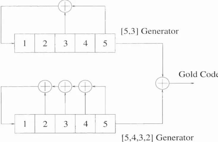
3.4.2 Gold co d es... 47
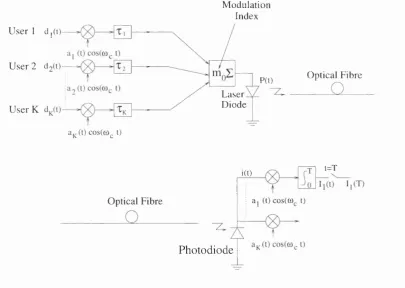
3.5 Modelling of a Optical Network Supporting CDMA S ig n a ls ... 49
3.6 Signal Processing W o rk sy stem ... 50
C O N T E N T S______________________________________________________________ vn
3.6.2 Custom-Coded B lo c k ... 51
3.7 DFB Laser M odelling... 52
3.7.1 Theoretical Model of DFB L a se r... 52
3.7.2 Creation of DFB Laser C C B ... 54
3.7.3 Simulation Example of the DFB Laser C C B ... 56
3.8 Simulation of a FO-CDMA S y s t e m ... 59
3.8.1 Selective Addressing C a p a b ility ... 59
3.8.2 Multiple Access C a p a b ility ... 62
3.8.3 Effect of the Spreading Sequence on the Laser-Induced N o n lin earity ... 64
3.9 S u m m a r y ... 66
4 Im p act o f Laser N on linear Effect On D irect Sequence /C D M A S ys tem s: M em oryless N o n lin earity 68 4.1 In tro d u c tio n ... 68
4.2 Laser Diode N o n lin earity... 69
4.2.1 In tro d u c tio n ... 69
4.2.2 Nonlinearity W ithout M em ory... 71
4.2.3 Third-Order In te rm o d u la tio n ... 73
4.3 The Effect of Imperfect Power Control on CDMA S y s te m s ... 79
4.3.1 Near Far P ro b le m ... 79
4.3.2 Case of BPSK S y s t e m ... 80
4.3.3 Case of QPSK S y s t e m ... 87
4.4 CDMA versus F D M A ... 89
C O N T E N T S_____________________________________________________________ vm
5 Laser N on lin earity on S C M /C D M A System s: V olterra A n alysis 93
5.1 In tro d u c tio n ... 93
5.2 System O utput as a Volterra Expansion ... 94
5.3 Determination of Nonlinear Laser Transfer Functions by the Probing Method ... 98
5.3.1 The Probing M e th o d ... 98
5.3.2 Nonlinear Laser Transfer F u n c tio n s ...100
5.4 Performance Assessment of SCM/CDMA S y s t e m s ...103
5.4.1 Laser Response to a sum of SCM/CDMA S i g n a l s ...103
5.4.2 Carrier to Noise R a t i o ... 106
5.5 S u m m a r y ... 107
6 S y stem s stu d ies 109 6.1 In tro d u c tio n ...109
6.2 Wireless Local Loop ...110
6.2.1 In tro d u c tio n ... 110
6.2.2 Digital Technologies ... 112
6.2.3 Intermodulation Power Spectral D e n s i t y ... 113
6.2.4 System P e rfo rm a n c e ... 118
6.3 Fibre Optic Microcellular R a d i o ...120
6.3.1 System C onfiguration... 120
6.3.2 M ultirate Radio Interface ...121
6.3.3 System P e rfo rm a n c e ... 124
6.4 SCM/CDMA Fibre Radio return l i n k ... 126
C O N TEN TS______________________________________________________________ ^
6.4.2 Expression of the Intermodulation P r o d u c t s ... 127
6.4.3 Intermodulation Power Spectral D e n s i t y ... 130
6.4.4 System P e rfo rm a n c e ... 132
6.5 S u m m a r y ... 135
7 C oncluding R em arks 136
A M u lti-U ser Interference 139
B D erivation o f th e T hird-O rder-Interm odulation Term s for C D M A
List o f Figures
2.1 Evolution of wireless networks ... 18
2.2 Hierarchical Cell Structure ... 20
2.3 Required data rate for different systems ... 21
2.4 Proposed MBS frequency a llo c a tio n s ... 22
2.5 Network c o n fig u ra tio n ... 24
2.6 Architecture of the 155 M bit/s multi 2M bit/s p l a t f o r m ... 26
3.1 Spread Spectrum S y ste m ... 35
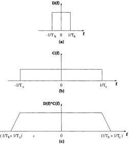
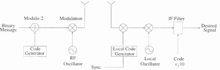
3.2 Convolution of spectra of the (a) data signal with the (b) PN code signal 36 3.3 Generation of a DS spread-spectrum signal... ... 38
3.4 A Direct Sequence Communications Link ... 39
3.5 Despreading operation: (a) The original message signal, (b) The received signal at each receiver, (c) The received signal after local multiplication. The desired signal is despread, (d) The signal after filtering. The inter ference outside the message signal BW is rejected... 40
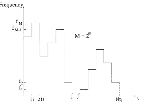
3.6 Frequency Hopping s i g n a l ... 41
3.7 Time hopping w a v e fo rm ... 42
3.8 Chirp-hopping s i g n a l ... 43
3.9 Linear PN code g e n e r a t o r ... 44
L IS T OF FIGURES_________________________ xi 3.11 Model of CDMA system in optical communication ... 49
3.12 Symbol model of laser ... 55
3.13 Param eters of l a s e r ... 56
3.14 Transient response for I = 30 mA (a), 35 mA (b) and 37 mA (c) . . . . 57
3.15 Modulation response for DFB Laser at 1 G H z ... 58
3.16 The reference code is identical to the one used by the transm itter for
c o d i n g ... 61
3.17 The reference code is desynchronised by one chip in respect with the
code used at the transm itter ... 61
3.18 The reference code and the code used at the transm itter are different . 61
3.19 Synchronous transmission of three users ... 63
3.20 Asynchronous transmission of three users ... 63
3.21 Asynchronous transmission of nine u s e r s ... 63
3.22 Comparison between m-sequence and m+1 sequence for 6 users . . . . 65
3.23 Comparison between Gold code and m+1 sequence for 6 u s e r s ... 65
3.24 Comparison between Gold code and m+1 sequence for 16 users . . . . 66
4.1 Sidebands and harmonics generated by a three-tone m odulation of a
laser diode ... 71
4.2 Idealized conversion from an electrical sinusoid into an optical sinusoid 73
4.3 BPSK CDMA System Model in Optical T ran sm issio n ... 74
4.4 Bit-Error-Rate versus the modulation index mo for BPSK based systems
L IST OF FIGURES________________________________________________________x ii
4.5 Bit-Error-Rate versus the number of users K for BPSK based systems for different values of the modulation index mo for the ideal case with
perfect power control and the practical case with imperfect power control 87
4.6 QPSK CDMA System Model in Optical T ransm ission... 88
4.7 Bit-Error-Rate versus the modulation index mo for QPSK based sys tems for different number of users K for the ideal case with perfect power control and the practical case with imperfect power control. The performance of the BPSK case with a standard deviation of 1 dB is also superimposed... 90
4.8 IM D /C versus modulation index with the number of users K & code period N as parameters for CDMA and FDMA s y s te m s ... 91
5.1 Nonlinear Model of the Semiconductor L a s e r ... 97
5.2 Block Diagram of a SCM/CDMA System ...106
6.1 Cell sites connected to central office (CO) ...113
6.2 Model of synchronous SCM/CDMA system in optical communication . 114 6.3 Carrier-to-Intermodulation ratio versus Optical m odulation depth for three users (-) and five users ( - . - ) ...119
6.4 Carrier-to-Intermodulation ratio versus Optical m odulation depth for bias current Jq = 40mA (-) and Jq = 55mA ( - . - ) ... 120
6.5 Flexibility of Services with CDMA ...121
6.6 Flexible mapping of service bit rates onto chip rates in the CODIT concept ... 123
6.7 Carrier-to-Intermodulation ratio versus Optical m odulation depth for four different services: 32 bkps (-), 64 bkps 144 bkps (- -) and 384 bkps ( . . . ) ... 125
L IS T OF FIGURES_______________________________________________________ ^ 6.8 Carrier-to-Intermodulation ratio versus Optical modulation depth for
384 kbps service with RF channel bandwidths of 5 (- -), 10 (-.-) and 20 (-) 125
6.9 Fusion of millimetre wave radio and optical fibre s y s te m s ... 127
6.10 Model of SCM/CDMA system in optical c o m m u n ic a tio n ... 128
6.11 Carrier-to-Intermodulation ratio versus Optical modulation depth for
two different sets of time delays: = 1/4 Tc, tj = 1/2 Tc and = 3/4
7:: (-); T, = 1 /4 0 T , , T, = 1 /3 0 = 1 /2 0 21: (- - ) ... 134
6.12 Carrier-to-Intermodulation ratio versus Optical modulation depth for
frequencies taken for three different bands: 2110 MHz (- -), 2140 MHz
List o f Tables
2.1 The different phases of the evolution of wireless communications . . . 25
5.1 Driving terms: equals 0 for n — 1 and Dn for the other cases...102
C hapter 1
In trod u ction
Code Division Multiple Access (CDMA) has been investigated over the past 15 years for
applications in optical fibre networks. Recently, there has been considerable interest in
using Spread Spectrum (SS) CDMA technology for microcellular mobile radio systems.
It is well known th at CDMA has the advantages of the large user capacity, the effective
utilization of the frequency and immunity to m ultipath fading over other multiple
access techniques. For the same reason^ it is effective to use SS/CDMA transmission
over optical fibre between base stations and control station [1]. However, the use of
Laser Diode in such a system leads to the generation of intermodulation products, which
consequently affect a system performance and ultimately restrain the maximum number
of users th at the system can serve. Many theoretical investigations and experiments
have been done for the study of this effect in the case of frequency-division multiple
access system [2, 3]. In this thesis, we examine the effect of Laser Diode nonlinearity
C H A P T E R 1. INTRO DU CTIO N
1.1
Thesis O rganisation
Following this introductory chapter, we present an overview of the different standards
used in wireless communications. We then present the new generation of wireless com
munications based on fibre-radio technologies. Finally, we described the multiple access
methods employed in the various standards.
In chapter 3 we focus our attention on the Spread Spectrum technology and its appli
cations. We pay particular attention to direct sequence technique and its derivative
CDMA. A Fibre Optic(FO)-CDMA system has been implemented using A lta’s Signal
Processing Worksystem (SPW) simulation framework. Properties of a CDMA network
have been emphasised by various simulations.
The impact of Laser Diode nonlinearity on the system performance is addressed in
chapter 4. This effect is modeled by a memoryless third-order polynomial. The expres-
sionsof the intermodulation terms for a CDMA system with unequal power transmission
are derived. The performance of the system is evaluated using the derived bit-error-
rate (BER) and a comparison between the ideal case and the practical case is provided.
In chapter 5 we present the theory to model the laser nonlinearity in the case of Subcar
rier Multiplexing CDMA systems. This analysis, based on Volterra functional series,
is first presented and then applied to the studied system.
The results of chapter 5 are applied in chapter 6 to study two im portant SCM/CDMA
systems namely: Wireless Local Loop and Mobile Radio systems.
Finally, chapter 7 concludes the thesis, summarising the main achievements and iden
C H A P T E R 1. INTRO DU CTIO N
1.2
C ontributions
The research reported here has sought to provide a detailed and comprehensive as
sessment of the performance of CDMA fibre optic systems, emphasis being placed on
the implications of laser nonlinearities. The main contributions of this thesis may be
summarised as follows:
• Development of a simulation platform on A lta’s SPW framework for study of
CDMA optical network. This model allows the simulation of different system
configurations in order to analyse the properties of CDMA system.
• Development of analytic expressions for laser diode nonlinearity for FO-CDMA
system taking into account unequal power.
• Extension of the volterra series analysis for SCM/CDMA systems to calculate
the third-order intermodulation products.
• Development of “software tools” implemented in M atlab and M athematica for
systems simulation.
Some of the contributions made during the course of this research have led to the
following publications:
• S. Geslin, S. L. Zhang, and J. J. O ’Reilly, “Simulation Tools for Study of CDMA
Optical Networks” , Proc. of the European Conference on Networks & Optical
Communications 1996 (NOC’96), pp. 149-156, Heidelberg, Germany, 25-28 June
1996.
• S. Geslin, S. L. Zhang, and J. J. O ’Reilly, “How the Choice of the Spreading
Di-CH A P T E R 1. INTRO DUCTION
gest of the Communications Research Symposium, pp. 73-76, University College
London, 29-30 July 1996.
• S. Geslin, J. Le Bihan, and J. J. O ’Reilly, “Modélisation et Simulation d ’un
Reseau Optique CDMA” , Journées Doctorales Informatique & Reseaux, pp. 8-
8/8-12, Ecole Nationale Supérieure des Telecommunications, Paris, 11-13 Sep.
1996.
• S. Geslin, A. Borjak, and J. J. O ’Reilly, “ The impact of imperfect power control
on direct-sequence CDMA in optical transmission” , lEE colloquium on CDMA
Techniques and Applications for Third Generation Mobile Systems, pp. 13/1-
13/5, London, 19 May 1997.
• S. Geslin, A. Borjak, L. Moura, and J. J. O ’Reilly, “The Implication Of Nonlinear
Effect On DS/CDMA W ith Imperfect Power Control In Optical Transmission” ,
1997 lEEE-MTT-S International Microwave Symposium Digest, June 8-13, Vol
ume III, pp. 1763-1766.
• S. Geslin, A. Borjak, and J. J. O ’Reilly, “The Effect of Laser Diode Nonlinearity
Direct-Sequence Code Division Multiple Access with Imperfect Power Control” ,
Proc. of the European Conference on Networks & Optical Communications 1997
(NOC’97), pp. 164-167, Antwerp, Belgium, 17-20 June 1997.
• Serge Geslin, Assaad Borjak, and John J. O ’Reilly, “The Effect of Nonlinear
ity on QPSK Based Direct-Sequence Code Division Multiple Access in Optical
C H A P T E R 1. INTRO DUCTION
C hapter 2
Towards th e D evelopm ent o f T hird
G eneration M obile
C om m unications System s
2.1
Introduction
This century has seen the development of a public wireline network th a t allows reliable
and affordable communication of voice and low-rate data around the globe. There is
also a multiplicity of specialised wired networks optimised for purposes such as the lo
cal communication of high-speed data. The goal of wireless communication is to allow
the user access to the capabilities of the global network at any time without regard
to location and mobility. In other terms, the vision of future telecommunications is
“information at any time, at any place, in any form” [4]. This requires the provision
of universal service access and mobility support, including both personal and term i
nal mobility. Therefore, emerging third-generation mobile telecommunications systems
C H APTE R 2. TO W ARD S THE D EVELO PM EN T ...___________________________ 7
basic and supplementary telecommunications services supported by fixed networks for
example, Public Switched Telephone Network (PSTN), Integrated Services Digital Net
work (ISDN), and Broadband ISDN (B-ISDN) and to other services specific to mobile
users.
A variety of services (e.g. paging, cellular) based on wireless communications already
exist today. Personal Communication Services (PCS), a family of communications ser
vices supporting personal handset and service mobility, represents the next generation
of personal services which rely on wireless communication technology. In particular,
these systems aim for the integration of all mobile radio applications (cordless, cellular,
and paging systems, including mobile satellite systems) into one universal system.
This chapter starts by presenting an overview of the current state of wireless com
munications with descriptions of first and second generation mobile communications
systems. Then, we discuss the challenge facing the development of the so-called third
generation mobile systems.
2.2
First G eneration M obile C om m unications
System s
The first generation mobile communications systems were introduced in the late 1970’s
and early 1980’s in analog form to provide local mobile speech services. These were
further extended to nationwide coverage in a number of countries. The user had to
subscribe to a single operator and hence user mobility was limited to the coverage of
the operator’s network. Various standard systems were developed and deployed world
wide: AMPS (Advanced Mobile Phone Service) in the United States, NTT (Nippon
Telephone and Telegraph) system in Japan, TACS (Total Access Communications
C H A P T E R 2. TO W AR D S THE D EVE LO PM EN T ...
tries, and so on.
Fast user growth was observed, penetrating up to 10% of the calls in North Amer
ica, Western Europe, and Japan. The access technique used was Frequency Division
Multiple Access (FDMA). Capacity and quality were the m ajor problems in the first-
generation systems, as well as being incompatible systems.
2.2.1
A nalog Cellular System s: A M P S and ETACS
In the late 1970s, AT&T Bell Laboratories developed the first U.S. cellular telephone
system called AMPS [5]. AMPS was first deployed in late 1983 in the urban and sub
urban areas of Chicago by Ameritech. In 1983, a total of 40 MHz of spectrum in the
800 MHz band was allocated by the Federal Communications Commission for AMPS.
In 1989, as the demand for cellular telephone services increased, the Federal Commu
nications Commission allocated an additional 10 MHz (called the extended spectrum)
for cellular telecommunications. The first AMPS cellular system used large cells and
omni-directional base station antennas to minimise initial equipment needs, and the
system was deployed in Chicago to cover approximately 2100 square miles. The AMPS
system uses a 7-cell reuse pattern with provisions for sectoring and cell splitting to in
crease capacity when needed. AMPS is used throughout the world and is particularly
popular in the U.S., South America, Australia, and China.
In Europe, several first-generation systems similar to AMPS have been deployed, in
cluding TACS in the United Kingdom, Italy, Spain, Austria and Ireland; NMT in many
countries; C-450 in Germany and Portugal; Radiocom 2000 in France; and RTMS (Ra
dio Telephone Mobile System) in Italy. The European Total Access Communication
System (ETACS) was developed in the mid 1980s, and is virtually identical to AMPS,
except th a t it is scaled to fit in 25 kHz (as opposed to 30 kHz) channels used throughout
C H AP T E R 2. TO W ARD S THE D E VE LO PM EN T ...___________________________9
of each subscriber (called the mobile identification or MIN) is formatted, due to the
need to accommodate different country codes throughout Europe and area codes in the
U.S.
2.2.2
F irst-G eneration A nalog Cordless
Since 1984, analog cordless telephones in the United States have operated on ten fre
quency pairs in the bands 46.6-47.0 MHz (base transm it) and 49.6-50.0 MHz (handset
transm it). Prior to 1984, five of the 49 MHz frequencies were paired with five fre
quencies near 1.6 MHz, an arrangement th at proved less than satisfactory due to the
imbalance in the performance of the two links and the limited number of channels. The
first cordless telephones were imported to Europe from the Far East and the United
States. In most of Europe, such equipment was illegal but was sold in large quantities
“for export only” . In the United Kingdom, a standard very similar to the one originally
used in the United States was introduced (MPT 1322) to offer an alternative to illegal
imports [6]. This standard (sometimes referred to as “CTO” ), allowed for eight channel
pairs near 1.7 MHz (base unit transm it) and 47.5 MHz (handset transm it), and most
units could access only one or two channel pairs. A similar standardisation approach
was adopted in France.
In the rest of Europe, the reaction to the demand for cordless communication was to
develop the analog cordless standard known as C E P T /C T l (Conference Européenne
des Postes et Télécommunications/ Cordless Telephone) [7]. This cordless standard
provides for forty 25 kHz duplex channel pairs in the bands 914-915/959-960 MHz (80
pairs are allocated for CT1+ in the bands 885-887/930-932 MHz, which do not overlap
with the GSM allocation) and form a Dynamic Channel Assignment scheme, whereby
one of the 40 (or 80) duplex frequency pairs is selected at the beginning of each call. In
C H A P T E R 2. TO W ARD S THE DEVE LO PM EN T ...__________________________W
(base transm it) allocated to analog cordless telephones using FM. The channel spacing
is 12.5 kHz and the allowed transm it power is 10 mW.
2.3
First to Second G eneration System s
Following the very great success of mobile cellular networks, based on analogue trans
mission, in penetrating the business market there was a clear need to introduce new
solutions based on the transmission of digitised voice or data in order to improve the
quality and range of services offered and to create a more efficient use of the allocated
spectrum. W ith remarkable foresight the European nations worked together to produce
the pan-European Global System for Mobile (GSM) standard, based on FDM A/TDM A
principles, which is now achieving sales worldwide. In the U.S., the need to introduce
more efficient digital networks was also perceived but, with a different commercial and
regulatory regime, several competing solutions have been developed including the first
commercial Code Division Multiple Access (CDMA) systems proposed alongside the
more usual FDM A/TDM A approaches. In particular the Qualcomm solution, based
on a narrow spread bandwidth of 1.23 MHz, has been specifically targeted at mobile
cellular operation. A U.S. interim standard, IS-95, has been w ritten around the Qual
comm system. The cellular world moves rapidly and the availability of new spectrum in
the 2 GHz region, plus technology improvements leading to the genuine pocket phone,
have led to the European PCN (Personal Communication Network) (or DCS1800, now
re-named GSM 1800) and the U.S. PCS concepts with market penetration expanding
rapidly in both the consumer and business sectors.
In the cordless world, the development of new digital technologies gave birth to Per
sonal Handyphone System (PHS, formerly PHP) in Japan, Digital Enhanced Cordless
C H A P T E R 2. TO W ARD S THE D E VELO PM EN T ...__________________________U
in North America. These may increase the call penetration depth up to 30% and in
troduce many new services. Although the second generation and its supplement will
cover local, national, and international services, it will still have one major drawback
in terms of universal service facility.
2.3.1
D igital Cellular System s
T he P an -E u rop ean G SM S y stem and G SM 1800
Global System for Mobile (GSM) is a second generation cellular system standard th at
was developed to solve the fragmentation problems of the first cellular systems in Eu
rope. GSM is the world’s first cellular system to specify digital modulation and network
level architectures and services. Before GSM, European countries used different cellu
lar standards throughout the continent, and it was impossible for a customer to use a
single subscriber unit throughout Europe.
GSM was originally developed to serve as a pan-European cellular service and promised
a wide range of network services through the use of ISDN. GSM’s success has exceeded
the expectations of virtually everyone, and it is now the world’s most popular standard
for new cellular radio and personal communications equipment throughout the world.
GSM was first introduced into the European market in 1991. By the end of 1993, sev
eral non-European countries in South America, Asia, and Australia had adopted GSM
and the technically equivalent offshoot, GSM 1800, which supports PCS in the 1.8
GHz to 2.0 GHz radio bands recently created by governments throughout the world.
It is predicted th at by the year 2000, there will be between 20 and 50 million GSM
C H A P T E R 2. TO W AR D S THE D E VE LO PM EN T ...__________________________U
IS-54 in N o rth A m erica
The first generation analog AMPS system was not designed to support the current
demand for capacity in large cities. Cellular systems which use digital modulation
techniques (called digital cellular) offer large improvements in capacity and system
performance [10].
After extensive research and comparison by major cellular manufacturers in the late
1980s, the United States Digital Cellular System (USDC) was developed to support
more users in a fixed spectrum allocation. USDC is a time division multiple access
(TDMA) system which supports three full-rate users or six half-rate users on each
AMPS channel. Thus, USDC offers as much as six times the capacity of AMPS.
The USDC standard uses the same 45 MHz FDD scheme as AMPS. The dual mode
USDC/AMPS system was standardised as Interim Standard 54 (IS-54) by the Elec
tronic Industries Association and Telecommunication Industry Association (EIA/TIA)
in 1990.
C D M A D ig ita l C ellular Standard: IS-95
A U.S. digital cellular system based on Code Division Multiple Access (CDMA) tech
nique which promised increased capacity [11] was standardized as Interim Standard
95 (IS-95) by the U.S. Telecommunications Industry Association (TIA). Like IS-54,
the IS-95 system is designed to be compatible with the existing U.S. analog cellular
system (AMPS) frequency band, hence mobiles and base stations can be economically
produced for dual mode operation. IS-95 allows each user within a cell to use the same
radio channel, and users in adjacent cells also use the same radio channel, since this is
a direct sequence spread spectrum CDMA system. CDMA completely eliminates the
C H A P T E R 2. TO W ARD S THE DEVE LO PM EN T ...__________________________13
To facilitate graceful transition from AMPS to CDMA, each IS-95 channel occupies
1.25 MHz of spectrum on each-way link, or 10% of the available cellular spectrum for a
U.S. cellular provider. Unlike other cellular standards, the user data rate (but not the
channel chip rate) changes in real-time, depending on the voice activity and require
ments in the network. Also, IS-95 uses a diflPerent modulation and spreading technique
for the forward and reverse links. On the forward link, the base station simultaneously
transm its the user data for all mobiles in the cell by using a different spreading sequence
for each mobile. A pilot code is also transm itted simultaneously and at a higher power
level, thereby allowing all mobiles to use coherent carrier detection while estim ating
the channel conditions. On the reverse link, all mobiles respond in an asynchronous
fashion and have ideally a constant signal level due to power control applied by the
base station.
2.3.2
D igital Cordless
Two second generation cordless telephone standards have been developed in Europe
for domestic and office applications, as well as for public telepoint services and radio
local loop. The first of the standards was CT2. This was followed by the ETSI DECT
standard which addressed the same markets while offering a higher capacity and greater
functionality. In Japan, PHS has been developed.
C T 2 C om m on Air Interface
CT2 is the second generation of cordless telephones introduced in Great Britain in 1989
[12]. The CT2 system is designed for use in both domestic and office environments. It
is used to provide telepoint services which allow a subscriber to use CT2 handsets at
a public point (a public telephone booth or a lamp post) to access the PSTN.
CH APTE R 2. TO W ARD S THE D E VELO PM EN T ...__________________________U
pared with analog cordless phones, CT2 offers good speech quality, is more resistant
to interference, noise, and fading, and like other personal telephones, uses a compact
handset with built-in antenna. The digital transmission improves security. Calls may
only be made after entering a PIN, thereby rendering handsets useless to unauthorised
users.
The CT2 standard defines how the Cordless Fixed Part (CFP) and the Cordless
Portable Part (CPP) communicate through a radio link. The CFP corresponds to
a base station and the CPP corresponds to a subscriber unit. The frequencies allo
cated to CT2 in Europe and Hong Kong are in the 864.10 MHz to 868.10 MHz band.
W ithin this frequency range, forty Frequency Division Duplexing (FDD) channels have
been assigned, each with 100 kHz bandwidth.
D ig ita l Enhanced C ordless Telephone
The Digital Enhanced Cordless Telephone (DECT) is a universal cordless telephone
standard developed by the European Telecommunications Standards Institute (ETSI).
It is the first pan-European standard for cordless telephones and was finalized in July
1992.
DECT provides a cordless communications framework for high traffic density, short
range telecommunications, and covers a broad range of applications and environments.
DECT offers excellent quality and services for voice and data applications. The main
function of DECT is to provide local mobility to portable users in an in-building Pri
vate Branch exchange (PBX). The DECT standard supports telepoint services as well.
DECT is configured around an open standard (OSI) which makes it possible to in
terconnect wide area fixed or mobile networks, such as ISDN or GSM, to a portable
subscriber population. DECT provides low power radio access between portable parts
CH APTE R 2. TO W ARD S THE D EVELO PM EN T ...__________________________ ^
P erson al H andy P h o n e S ystem
In 1989, the Japanese Ministry of Posts and Telecommunications set up a group to
define the requirements for the introduction of Personal Handy Phone System (PHPS)
for digital cordless telephonic applications. The PHPS standard was finally published
in March 1983. Voice and data services have been defined, including circuit and packet
d ata transmission with a maximum bit rate of 128 kb/s. Around 20 supplementary
services are also specified (e.g. automatic call back, call forwarding, calling number
identification) and the protocol incorporates expansion capabilities for additional fea
tures.
For residential use, both incoming and outgoing calls are possible and in addition, two
terminals may communicate directly (without going through the base station) if they
are close enough. The PHPS standard benefits from a frequency allocation of 77 carri
ers in the 1900 MHz band. The air interface is based on TDM A /TD D access method
with eight time slots per frame and allows four bidirectional communications per 300
kHz wide carrier.
2.4
Third G eneration W ireless N etw orks
W ith the current rapid growth of technology, it can now emphatically be said th a t the
objective of today’s communication engineers to achieve a Future Wireless Personal
Communication (FW PC) system, which was yesterday’s myth (before 1970) will be
tomorrow’s reality (beyond 2 0 0 0).
These third generation wireless systems will evolve from m ature second generation sys
tems. The aim of the third generation wireless networks is to provide a single set of
standards th at can meet a wide range of wireless applications and provide universal
C H A P T E R 2. TO W ARDS THE D E VELO PM EN T ...__________________________IR
between cordless telephones and cellular telephones will disappear, and a universal
personal communicator (a personal handset) will provide access to a variety of voice,
d ata and video communication services, will operate in varied region (dense or sparsely
populated regions), and will serve both stationary users and vehicular users travelling
at high speeds [14]. Third generation systems will use the Broadband Integrated Ser
vices Digital Networks (B-ISDN) to provide access to information networks, such as
the Internet and other public and private databases.
Thus, FW PC systems will convert the already shrinking world into a global village.
An FW PC, defined as being the ultim ate goal of today’s communication engineers,
will provide communication services from any person to any person in any place at any
time without any delay in any form through any medium by using one pocket-sized unit
at minimum cost with acceptable quality and security through the use of a personal
telecommunication reference number.
The IMT-2000 (International Mobile Telecommunications beyond the year 2000), pre
viously known as FPLMTS (Future Public Land Mobile Telecommunication System)
will set the scope for the third generation wireless systems and will consolidate a range
of term inal mobility services under a single global standard. The IMT-2000 standard
is intended to ensure interoperability across different wireless environments (cellular
mobile, cordless telephony, satellite mobile services) and mobility on a global scale.
In Europe, the objectives of the research and development of FW PC systems are fo
cused in three technological platforms [13]: Universal Mobile Telecommunication Sys
tems (UMTSs), Mobile Broadband Systems (MBSs), and Wireless Local Area Networks
C H A P T E R 2. TO W ARD S THE D E VE LO PM EN T ...__________________________U
2.4.1
P C S D efinition
The terms Personal Communication System (PCS) or Personal Communication Net
work (PCN) are used to imply emerging third generation wireless systems for hand-held
devices. The definition of PCS has evolved over time. Some of the earlier definitions
have been as follows:
• An extension and integration of current and emerging wired and wireless telecom
munications network capabilities allowing, ultimately, communication with per
sons.
• A wide array of personal communications services: cellular, cordless phones,
paging, wireless private branch exchange (PBXs), WLANs, and so on.
The current definition of PCS can be found in the American National Standards In
stitute (ANSI) approved standard, “Personal Communications Terminology” (ANSI
T l . 702-1995), and readsas follows: “A set of capabilities th at allows some combination
of terminal mobility, personal mobility, and service profile management” . PCS is a
new concept which will expand the horizon of wireless communications beyond the
lim itations of current cellular systems to enable communication with a person, at any
time, at any place, and in any form [15]. The enabling concepts for providing uni
versal personal communications include terminal mobility provided by wireless access,
personal mobility based on personal numbers, and service portability through man
agement of user service profiles. Because of the inherent nature of mobility associated
with personal communications, wireless communications and PCS have now become
almost inseparable concepts.
Today, personal communication services are provided by a range of first and second
generation networks and technologies. The terms first and second generation refer
CHAPTER 2. TOWARDS THE DEVELOPMENT ... 18
1st G e n e r a t io n 2 n d G e n e r a t io n 3 r d G e n e r a t io n
1980s : 2000s
I n itia l S t a g e c = $ > G r o w i n g S t a g e E x p a n s i o n S t a g e i = 0 P r o s p e r o u s S t a g e
A n a l o g C e ll u l a r
A M P S / N - A M P S ( U S A )
T A C S / E T A C S ( U K )
N M T ( S c a n d i n a v i a )
D i g i t a l C e ll u l a r
l S - 5 4 / 9 5 ( U S A )
G S M / D C S 1 8 0 0 ( E u r o p e )
P D C 8 0 0 / 1 5 0 0 (J a p a n )
C T -1 ( U K )
A n a l o g u e C o r d l e s s !=0
D i g i t a l C o r d le s s
C T - 2 ( U K & R O T W )
D E C T ( E u r o p e )
P H S ( J a p a n )
F u tu r e S y s t e m s
F P L M T S ( I T U - T )
U M T S ( E T S l - S M G )
M B S ( E U )
Figure 2.1: Evolution of wireless networks
key cliaracteristic foreseen for the third generation is that of bringing together all the
attributes of personal communications into a single unified system. First generation
celhdar systems are usually national or regional standards, e.g. AMPS in the U.S.,
TACS in the UK. This has restricted the market for each system, and has tended to
limit the scope for users to take their mobiles outside their home networks.
GSM addressed this problem by standardising the radio and network interfaces, im
posing rigorous type approval of mobile equipment, and requiring GSM operators to
establish technical and commercial roaming agreements. As a result, subscribers can
use the GSM system when abroad, provided their home network has a roaming agree
ment with the local GSM operator.
2.4.2
UMTS: The Cellular Concept
Europe is taking a leading position in the definition of third generation mobile since
it is expected that mobile and personal communications will become a key driver for
growth and innovation in the next millennium as well as being a necessary building
block of the Wireless Information Society. UMTS moves mobile and personal
C H A P T E R 2. TO W ARD S THE D E VELO PM EN T ...__________________________W
munications forward from second generation systems th at are delivering mass market
low-cost digital telecommunications services. UMTS is the third generation mobile
standard th at links mobile personal communications users into networked broadband
multimedia, information-technology and telecommunications services and applications
for Europe and the global society [16]. Movement towards this new opportunity will
be driven by new applications, liberalisation, social demand, seamless mobile and fixed
network access, operating environments, implementation and timing. UMTS’s technol
ogy must encourage this movement by naturally fostering innovation and competition.
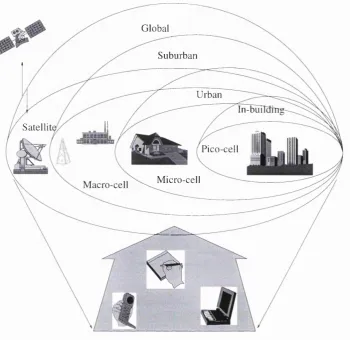
One m ajor distinction of UMTS relative to second generation systems is the hierarchical
cell structure designed for gradated support of a wide range of multimedia broadband
services within the various cell layers by use of advanced transmission and protocol
techniques, as indicated in Figure 2.2. Second-generation systems are mainly based on
a single-layer cell structure employing frequency reuse within adjacent cells in such a
way th a t each single cell is capable of managing its own radio zone and radio circuit
control within the mobile network, including functions such as traffic management and
handover procedures. The traffic supported in each cell is fixed because of frequency
lim itations and little flexibility of radio transmission mainly optimised for voice and
low rate d ata transmission. Increasing traffic leads to costly cellular reconfigurations
such as cell splitting and cell sectorisation. The multilayer cell structure in UMTS aims
to overcome these problems by overlaying, discontinuously, pico- and microcells over
the macro-cell structure with wide area coverage. The various cells shown in Figure
2 .2 differ mainly in terms of size, channel, and propagation characteristics. As a conse
quence, the above differences result in a different set of services and mobility features
CHAPTER. 2. TOWARDS THE DEVELOPMENT ... 20
Global
Suburban
Urban
In-bui
Satellit
Pico-cell
M icro-cell Macro-cell
Figure 2.2; Hierarchical Cell Structure
The radio-cell architecture consists of
• inega-cells using satellites for remote areas,
• macro-cells for wide area (ubiquitous) coverage,
• rnicro-cells supporting high density urban areas,
• pico-cells for indoor use.
Due to low mobility support and smaller delay spread in picocells, high bit rates and
traffic density can be supported with low complexity as opposed to lower bit rates and
traffic load in macrocells, supporting high mobility and resistance against higher delay
spread by robust transmission techniques.
CHAPTER. 2. TOWARDS THE DEVELOPMENT ... 21
2.4.3
Mobile Broadband Systems
The realisation of the B-ISDN based on optical fibres, the increasing demand for high
data rate transmission and the requirement for mobility lead to the concept of Mobile
Broadband Systems (MBS) [17, 18, 19]. MBS was in fact a European project as part of
the RACE programme. With high data rate exchange up to about 100 Mbit/s, MBS
would “fill the gap” between the fixed B-ISDN and UMTS as it is shown in Figure 2.3.
The MBS will use Asynchronous Transfer Mode (ATM).
fast m ob ile
slo w m ob ile
m ovab le
fixed
UMTS
.. A"7" '
MBS
'6 ?
ISDN
9.6
kbit/s
155
M bit/s
Figure 2.3: Required data rate for different systems
It will typically support services above 2 Mbit/s but lower rate could also be used as
for UMTS. Applications of the MBS depend on the quality of service available. There
will be a transmission from point-to-point links to point-to-multipoint links. The MBS
project has proposed the use of two wavebands, the 60 GHz band for very small cells
(picocells) and the 40 GHz band for larger cells. Figure 2.4 shows the proposals.
MBS is investigated for microcellular networks for which at least 40 frequency channels
transmitting 34 M bit/s each must be made available with a typical cell radius of 100
m. A channel spacing of 50 MHz therefore leads to a spectrum requirement around 2
C H A P T E R 2. TO W ARD S THE D E VELO PM EN T ... 22
MBS MBS
a) 62 63 64 65 66
b) 39.5 40.5 41.5 42.5 43.5
a) 60 GHz band proposal
b) 40 GHz band proposal
Figure 2.4: Proposed MBS frequency allocations
2.4.4
W ireless Local Area N etw orks
Proliferation of portable and laptop computers, wide acceptance of mobility, and po
tential cost savings in avoiding the wiring or rewiring of buildings are driving forces for
broadband wireless access for in-building environments. Consequently, third generation
mobile systems must incorporate an integrated Wireless Local Area Network (WLAN)
capability to maintain “universality” . Application areas include mobile systems for
offices, industrial automation, financial services, medical and hospital systems, and
education and training, with network connection for portable computers and personal
digital assistants as well as ad hoc networking.
In creating a high-rate (up to 155 M bit/s) local data communication link, significant
research is required to identify reliable system and associated air interface. Im portant
issues include frequency allocation and selection, choice of bandwidth efficient coding
schemes, specification of medium access procedures, definition of link control proto
cols as well as connectivity aspects related to connection to other wired or wireless
communications networks. In brief, the WLAN R&D activities seek for solutions th at
recognise application, environment, cost, performance, networking and system archi
C H A P T E R 2. TO W ARDS TH E D E VE LO PM EN T ...__________________________ ^
2.5
W ireless C om m unications B ased on Fibre-R adio
Technologies
Wireless communications have become a significant area of growth within the last few
years [20, 21]. There is a diverse range of products and services currently on the market,
but cellular or personal communications services (PCS) radio networks probably have
the highest public profile [22]. These services provide highly mobile, widely accessible
two-way voice and data communications links [23].
At the same time, optical fibre networks as the high capacity trunk transmission have
favourably progressed. Moreover, wired systems represented by optical fibre commu
nication, and wireless systems including long-haul microwave communication, satellite
communication, mobile communication and indoor radio - both of these wired and wire
less systems have made remarkable advance and development with highly developed
theory and technology.
2.5.1 S ystem Configuration
Future third-generation mobile systems will require the support of an integrated op
tical network infrastructure, as cell size decreases and narrow-band telephony services
migrate from fixed copper wire connections to mobile radio. Therefore, tomorrow’s
communication networks would employ wireless media in the local area and utilise
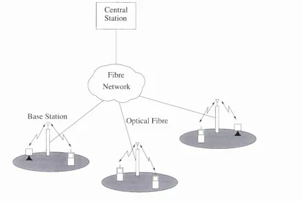
high-capacity wired media in the m etropolitan and wide-area environments. A new
transmission medium has been born in which radio waves are carried from base sta
tions (BS) to the central station (CS) by optical fibre and thereafter propagated in the
atmosphere. An example of such a network is provided in Figure 2.5. In this system,
radio base stations are connected with optical fibres and millimetre waves are used for
CHAPTER 2. TOWAlRDS THE DEVELOPMENT 24
C entral Station
Fibre
N etw o rk
B a se Station
Y O ptical Fibre
Figure 2.5: Network coiifigiiration
provide coiiiiniinication capability between moliile terminals but will also ])ermit these
mobile devices to have access to “wired” networks.
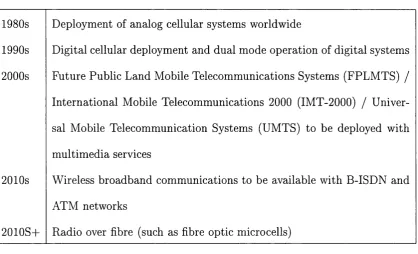
Ill Tal)le 2.1, the different phases of the evolution of wireless communications are sum
marised.
2.5.2
FR A N S project
In Europe, R&D on Third Generation technology falls under the European Community
RACE (Research into Advanced Communications in Europe) and ACTS (Advanced
Communications Technologies and Services) programmes [24]. The main objective of
the R ACE programme, in the context of mobile and personal communications, was the
CH APTE R 2. TO W ARD S THE D E VELO PM EN T ... 25
1980s
1990s
2 0 0 0s
2 0 1 0s
2 0 1 0S+
Deployment of analog cellular systems worldwide
Digital cellular deployment and dual mode operation of digital systems
Future Public Land Mobile Telecommunications Systems (FPLMTS) /
International Mobile Telecommunications 2000 (IMT-2000) / Univer
sal Mobile Telecommunication Systems (UMTS) to be deployed with
multimedia services
Wireless broadband communications to be available with B-ISDN and
ATM networks
Radio over fibre (such as fibre optic microcells)
Table 2.1: The different phases of the evolution of wireless communications
development and validation of the necessary key technologies and concepts th a t would
in the future constitute the “building blocks” of the UMTS system. The ACTS pro
gramme, while capitalising on the RACE experience, is conceived as a demand-driven
R&D program of demonstration trials th at will prepare the ground for a European-
wide, internationally competitive broadband telecommunications infrastructure th a t
naturally has a mobile communication dimension.
One of the ACTS projects, FRANS (Fibre Radio ATM Networks and Services), is
concerned with field trials demonstrating an optically supported millimetre wave radio
link as a final drop to provide rapid, flexible deployment of broadband interactive ser
vices. It merges existing passive optical networks (PONs) with a photonic technique
for generation, modulation and transmission of information bearing millimetre wave
signals to a hybrid fibre radio customer access system. Two trials are planned, using
different bit rates and based on different multiple access techniques in the uplink.
CHAPTER 2. TOWARDS THE DEVELOPMENT ... 26
A 622 M bit/s downlink with TDMA uplink of 40 M bit/s aggregate ( ~ 2 M bit/s
per user), both with millimetre wave radio part working in the 30 GHz range.
A 155 M bit/s downlink with millimetre wave radio interface at ~30 GHz and
G DAI A uplink ( 1 -5 x 2 M bit/s per user) with a microwave radio part at ~2.5
GHz (Figure 2.6).
m in - w a v e
d o w n - lin k R e m o te A n te n n a
T x U n it m m - w a v e
d o w n - lin k
O p tic a l
S p litte r A T M
R e m o te A n te n n a
R x U n it
S e r v i c e s m ic r o w a v e
u p l i n k m ic r o w a v e
^ u p -Iin k
N e t w o r k L T
C D M A
R x O p tic a l m m - w a v e
S o u r c e
A d m i n i s t r a t i o n
Figure 2.6: Architecture of the 155 M bit/s rmdti 2 AI bit/s platform
The downlink is based on a principle developed in RACE 2005 (AIODAL). Two optical
spectral components, separated by the required millimetre wave frequency, are gener
ated and modulated in a central unit and distributed via a PON to antenna sites close
to the users, where the two components mix in a PIN photodiode and a modulated
millimetre wave signal is generated and radiated. The TDAIA uplink uses a different
millimetre wave frequency, remote down conversion in the antenna unit and microwave
transport over the PON to the central unit. The CD AI A uplink uses a microwave car
C H APTE R 2. TO W ARD S THE D E VE LO PM EN T ...__________________________ ^
rier frequency transm itted directly to the central unit or over a hbre-optically remoted
antenna.
2.6
M ultiple A ccess Techniques for W ireless
C om m unications
2.6.1 Introduction
Multiple access schemes are used to allow many mobiles to share simultaneously a
finite amount of radio spectrum. The sharing of the spectrum is required to achieve
high capacity by simultaneously allocating the available bandwidth (or the available
amount of channels) to multiple users. For high quality communications, this must be
done without severe degradation in the performance of the system.
In wireless communications systems, it is often desirable to allow the subscriber to
send simultaneously information to the base station while receiving information from
the base station. For example, in conventional telephone systems, it is possible to
talk and listen simultaneously, and this effect, called duplexing, is generally required
in wireless telephone systems. Duplexing may be done using frequency and time do
main techniques. Frequency Division Duplexing (FDD) provides two distinct bands
of frequencies for every user. The forward band provides traffic from the base station
to the mobile, and the reverse band provides traffic from the mobile to the base. In
FDD, any duplex channel actually consists of two simplex channels, and a device called
a duplexer is used inside each subscriber unit and base station to allow simultaneous
radio transmission and reception on the duplex channel pair. The frequency split be
tween the forward and reverse channel is constant throughout the system, regardless
C H AP T E R 2. TO W ARD S THE D EVELO PM EN T ...__________________________ %
stead of frequency separation to provide both a forward and reverse link. If the time
split between the forward and the reverse time slot is small, then the transmission
and reception of data appears simultaneous to the user. TDD allows communication
on a single channel (as opposed to requiring two simplex or dedicated channels) and
simplifies the subscriber equipment since a duplexer is not required.
2.6.2
M ultiple A ccess M eth ods
Frequency Division Multiple Access (FDMA), Time Division Multiple Access (TDMA),
and Spread Spectrum Multiple Access (SSMA) are the three major access techniques
used to share the available bandwidth in a wireless communication system [25].
FDMA was the earliest and is the simplest form of multiple access. W ith FDMA
the available channel bandwidth is subdivided into a number, say N, of frequency
non-overlapping subchannels and a subchannel is assigned to each user upon request.
FDMA is commonly used in wireline channels to accommodate multiple users for voice
and d ata transmission.
TDMA is another method for creating multiple subchannels for multiple access. In
this method, the duration Ty, called the frame duration, is subdivided into, say N,
non overlapping subintervals, each of duration, Tf / N. Then each user who wishes to transm it information is assigned to a particular time slot within each frame. TDMA
is frequently used in data and digital voice transmission.
W ith FDMA and TDMA, problems arise when the data from the users accessing the
network is bursty in nature. In other words, the information transmissions from a
single user are separated by periods of no transmission, where these periods of silence
may be greater than the periods of transmission. Such is the case generally with users
at various terminals in a computer communications network th at contains a central
sys-C H APTE R 2. TOW ARDS THE D EVE LO PM EN T ...__________________________ ^
terns carrying digitised voice, since speech signals typically contain long pauses.
In such an environment where the transmission from the various users is bursty and
low-duty cycle, FDMA and TDMA tend to be inefficient because a certain percentage
of the available frequency slots or time slots assigned to users do not carry informa
tion. Ultimately, an inefficiently designed multiple access system limits the number of
simultaneous users of the channel.
An alternative to FDMA and TDMA is to allow more than one user to share a channel
or subchannel by use of spread spectrum multiple access technique [26]. This method
will be described in detail in the next chapter.
2.7
Sum m ary
In this chapter, an overview has been given of the current state of wireless commu
nications with a presentation of the different standards. The first generation mobile
communication systems were introduced at national level, for example NMT in Scandi
navia, AMPS in the U.S. and TAGS in the UK. These systems use analogue modulation
and were specified essentially as separate dedicated systems for paging, cordless phone,
mobile terrestrial and mobile satellite communication. In the early 1990s, second gen
eration systems started to be introduced at regional (continental) level, e.g. GSM in
Europe, Australasia, India and the Gulf States. These systems use digital modulation
techniques.
The next step, now expected for the first decade of the next century, will be the in
troduction of a global system called UMTS in Europe and FPLMTS in the rest of the
world. This system, which will use digital modulation techniques and support bit-rates
of up to 2 M bit/s, is based upon 2 GHz technology and will possibly merge paging,
C H APTE R 2. TO W ARD S THE D E VELO PM EN T ...__________________________^
standard.
Beyond the year 2000, mobile broadband applications are expected to become more
and more im portant, at least in some environments. As a consequence, bandwidth has
been provisionally identified in the 40 to 60 GHz range for a MBS supporting services
requiring transmission rates up to 155 M bit/s.
Furthermore, to respond to the increasing demand for broadband services, in the near
future, a new generation of wireless communications based on fibre-radio technologies
will be developed. These networks will allow end-to-end connectivity on all-optical
paths, removing some of the existing bandwidth limitations.
We have also described the multiple access methods used in wireless systems. In the