DOI 10.1007/s11036-010-0270-6
A Resource Allocation Framework for Scalable Video
Broadcast in Cellular Networks
Daniele Munaretto·Dan Jurca·Joerg Widmer
Published online: 15 October 2010
© Springer Science+Business Media, LLC 2010
Abstract Video streaming is one of the most important
applications that will make use of the high data rates offered by 4G networks. The current video transport techniques are already very advanced, and the more immediate problems lie in the joint optimization of video coding, AL-FEC, and PHY rate selection with the goal of enhancing the user perceived quality. In this work we provide an analysis of video broadcast streaming services for different combinations of layered coding and AL-FEC, using a realistic LTE PHY layer. Our simulation results show that the scalable content adaptation given by Scalable Video Coding (SVC) and the scheduling flexibility offered by the 3G-LTE MAC-layer provide a good match for enhanced video broad-cast services for next generation cellular networks. Our proposed solution is compared to baseline algorithms and broadcast systems based on H.264/AVC streaming solutions. We emphasize the system quality improve-ment brought by our solution and discuss implications for a wide-scale practical deployment.
Keywords broadcast video streaming·H.264
AVC/SVC·AL-FEC·cross-layer optimization·LTE
D. Munaretto (
B
)·D. Jurca·J. WidmerDOCOMO Communications Laboratories GmbH, Munich, Germany
e-mail: [email protected] D. Jurca
e-mail: [email protected] J. Widmer
e-mail: [email protected]
1 Introduction
Wireless broadcast video streaming is one of the most important services offered by the next generation of cellular networks. Adaptability to the time-varying channel conditions and robustness against channel losses have an impact on the reliability of the video transmission, and hence on the video quality perceived by the end users. The more immediate problems related to the current advanced video transport techniques lie in the joint optimization of the coding techniques used to compress the streamed video and to pro-tect it against channel erasures, and the channel rates available at the base stations to transport the video packets.
In this paper, we design heuristic cross-layer algo-rithms which make use of higher order modulation and coding schemes for higher quality video layers, to pro-vide differentiated service quality to a heterogeneous set of users, thus improving the overall video quality. To do so, we solve the problem of jointly optimizing the number of scheduled video layers, AL-FEC, and modulation and coding schemes for a broadcast stream-ing application, based on a mathematical cross-layer framework.
The goal of our framework is to minimize the overall video distortion perceived by the end clients (e.g. mo-bile phones, PDAs, laptops), making use of:
• the video quality scalability offered by the
H.264/SVC codec at the application layer;
• unequal error protection at the application layer
(AL-FEC), which increases the robustness of the transmitted information to channel errors;
• the flexible MAC layer scheduling offered by
3G-LTE (different modulation and coding schemes, MCs), realized both in time and frequency do-mains using OFDMA, to provide efficient broad-cast video streaming solutions in a cellular system.
The contributions of this work can be summarized as follows:
• we define a cross-layer optimization framework for
a streaming broadcast system based on the opti-mization of the overall system perceived distortion;
• We derive a heuristic approach for: 1) the
computa-tion of the best modulacomputa-tion and coding schemes for each user; 2) the assignment of the modulation and coding scheme to each single video layer scheduled for transmission; 3) the computation of AL-FEC redundancy required for each video layer, taking into account the channel constraints;
• We perform exhaustive simulations for a wide
range of settings in order to validate our frame-work;
• We compare our solution to other broadcast
solu-tions based on H.264/AVC.
• We discuss a possible system architecture based
on our cross-layer framework, in which we can implement our algorithm as a module at the base station in a cellular system;
• We further discuss issues related to a possible
wide-scale deployment of our broadcast system by a mobile operator.
The remainder of the paper is organized as follows.
In Section2we report on the related work. In Section3
we introduce our cross-layer framework and discuss the
optimization problem. Section 4 presents our
heuris-tic approach to solve the optimization problem. Our
delivery architecture is presented in Section5and the
simulation setup and results are provided in Section6.
A short discussion on the practical issues to be
evalu-ated in a real deployment is given in Section7and we
conclude the paper in Section8.
2 Related work
In advanced wireless technologies such as 3GPP/LTE
[1, 2], broadcast video streaming is considered to be
one of the most important applications that need to meet the requirements and capabilities of a wide range of mobile devices, with respect to available com-puting resources, power consumption, spatial resolu-tion of the screen, rate, etc. Scalable Video Coding
(H.264/SVC) [3] supports heterogeneous devices and
users with different channel conditions by allowing a source (server) to send a video with scalability pro-vided in either the temporal, spatial, or quality
do-main [4]. In order to provide protection to the video
packets against losses, several FEC techniques have been proposed for broadcast scenarios. Raptor Codes
[5], one of the first known classes of fountain codes
with linear time encoding and decoding, offer a widely used and highly efficient FEC solution. It has been adopted in 3GPP for mobile cellular wireless broadcast and multicast applications and is also used by
DVB-H [6] standards for IP datacast to hand-held devices.
The FEC redundancy sent alongside with the original packets can be increased for the most important video layers (Unequal Error Protection, UEP),
outperform-ing regular robustness schemes [7,8]. In general, the
video transport techniques adopted by the standards for broadcast video streaming applications in cellular networks are very advanced. At the same time, several cross-layer studies for robust scalable unicast/broadcast video transmission over WLANs have been proposed,
e.g. [9], showing that real-time video quality can be
improved by cross-layer signaling [10]. Studies on how
to determine which PHY layer modulation and coding scheme the base station should use to broadcast packets
were recently presented in [11], but they mainly
fo-cus on ARQ-based protection mechanisms rather than FEC techniques.
distortion model encompassing both the source video distortion and the influence of channel errors. We also present novel algorithms for solving our optimization problem in a tractable way, by isolating the most impor-tant factors influencing the distortion metric. Finally, our results open interesting discussion points related to the practical deployment of our proposed broadcast system by a mobile operator.
3 Model
3.1 System model
We consider a wireless video broadcast system in which a base station delivers video content to N clients inside its coverage area. The channel used for the transmission has a capacity of C symbols per second, which can be translated into an application rate, based on the
modu-lation and coding scheme (MCi) used for transmission.
We assume that the base station can choose the
ap-propriate MCiout of a set of available schemesMC=
{MCi|1≤i≤M}. Then, the channel capacity Ci used
for transmission is a function of the application rateρi
and the modulation and error correction code rate used
by the chosen MCi: Ci= f(ρi,MCi). Each client j in
the coverage area of the base station can decode the
transmitted information sent with MCi with a certain
error probability pi,j≤1, based on the observed
signal-to-noise ratio of its down-link channel. We assume that the base station obtains feedback about the SNR levels for all its clients and, based on the SNR, can estimate the loss probability observed by each user, for each of the available MC schemes.
The video stream broadcasted by the base station is encoded into L scalability layers using a scalable video encoder, i.e., one base layer, containing the most im-portant video packets for a minimum video quality, and
L−1enhancement layers, each one further improving
the quality over the lower layers. We assume that video
layer k, of rateρk, can only be decoded at the clients if
all lower video layers are successfully decoded, and that each video layer can be truncated before transmission, based on the total available channel rate. The base station has the flexibility of choosing an appropriate
MC(k) for each individual transmitted video layer k.
Furthermore, it can protect each layer k against chan-nel errors through an application layer forward error
correction scheme FECk. Finally, we assume that the
wired backbone link between the application server, providing the video content, and the base station is over-provisioned and lossless.
3.2 Video distortion model
We represent the end-to-end video distortion, as per-ceived by one media client j, as an additive metric
Dj depending on both the source distortion and the
channel distortion (in terms of MSE). Thus, the re-ceived video quality depends on the lossy encoding
of the media information (DS) and on the amount of
packet loss experienced in the network during the video
transmission (DL).
The source distortion DSdepends on the total video
rate Rv(l)of the l≤L video layers scheduled for
trans-mission by the server. If fk∈ [0,1]represents the
trun-cating factor of video layer k, then Rv(l)=lk=1 fkρk.
In contrast, DL is roughly proportional in average to
the number of lost pixels/video elements. As network packets contain in general data referring to the same amount of video information (e.g., one frame, one slice, or one encoded video layer of a frame), the channel distortion is proportional to the number of lost packets, and is differentiated by the importance of the video
layer containing the lost packets [12]. If Rv(l) is the
video rate scheduled for transmission, we can explicitly formulate the video distortion metric as:
Dj(l)=DS(l)+λπ1j
+
l
k=2 (πj
k(DS(k−1)−DS(l)) k−1
s=1
(1−πsj))
where DS(l)can be computed based on the encoding
parameters and our transmission assumptions, using
a linear approximation for truncated layers. πkj
rep-resents the loss process affecting the transmission of video packets belonging to layer k after FEC
decod-ing, at user j, and λ is a video sequence dependent
constant. In our transmission context, packets from different video layers k are transmitted using
poten-tially different modulation and coding schemes MC(k)
and are protected by different amounts of FEC
(appli-cation layer unequal error protection – FECk), hence
πkdiffers from layer to layer.
Finally the total distortion of our broadcast scenario can be computed as the sum of the individual distor-tions perceived by all users in the system:
D(l)=
N
j=1
Dj(l)
Note that the total distortion of our broadcast sce-nario depends on the total number of clients in the
sys-tem N, and their respective channel conditions SNRj,
1≤ j≤N, the number of video layers transmitted l, the
layer MC(k),1≤k≤l, and the amount of application
layer FEC added to each layer FECk,1≤k≤l.
We validate the distortion model through video ex-periments, using more encoded video sequences with
300 frames, using the JSVM encoding software [13].
Due to space constraints, we omit the validation results in this paper. However, we refer the interested reader
to [14] for a complete discussion of these results.
3.3 Unequal error protection
We use a systematic error correction code which
pro-tects each block of s video packets by adding n−s
redundant packets, hence creating a FEC block
FEC(nk,sk)for each video layer k. We assume that the
s video packets can be reconstructed as long as no more
than n−s packets are lost from the transmitted FEC
block. The average loss probability as seen by video layer k packets after FEC decoding can be computed as:
πk= 1
s ·
s
i=1
i·ei(n,s),
where ei(n,s) is the probability of losing at least
n−s+1 packets from the FEC block, out of which
exactly i packets are video packets. Assuming an
in-dependent model for the channel packet losses, ei(n,s)
can be easily computed:
ei(n,s)=
s i
pi(1−p)s−i
s
l=max(b+1−i,0)
b
l
pl(1−p)b−l,
where b=n−s. The rate of video layer k protected by
a FEC scheme FEC(nk,sk)increases toρk =ρknksk.
In streaming applications, where transmission delay should be kept small, it is common to form short-to-medium length FEC blocks, based on independent blocks from the video bitstream, e.g., s could represent the number of packets in one GOP of one scalability layer in the encoded bitstream.
3.4 Optimization problem
Finally, we formulate the optimization problem. We are interested in finding the optimal broadcast strategy at the base station, which minimizes the total video distor-tion perceived at all the clients, under a given channel capacity constraint. With this respect we must find the optimal number of video layers to be transmitted, the appropriate modulation and coding scheme for each video layer, and the right amount of AL-FEC protec-tion for each transmitted layer. We aim at optimizing out broadcast strategy periodically, in order to reflect
the changes in the overall system, be it number of users and their respective channel conditions, availability of different modulation and coding schemes, or changes in the video stream parameters.
Formally, our optimization problem can be stated as follows. Given the total number of users N and
their respective channel conditions SNRj,∀j≤N, the
available modulation and coding scheme set MC=
{MCi|i≤ M}, the statistics of the video bitstream
ρk,∀k≤ L and s, and the channel capacity constraint
C, find the optimal resource allocation tuple (l, MC(k), FECk)∗with1≤k≤l such that:
(l,MC(k),FECk)∗= arg min
∀(l,MC(k),FECk)D(l) (1)
under the total channel rate constraint:
l
k=1
fkf(ρk,MC(k))
nk
s ≤C
Given the dependency of the distortion metric on so many parameters, the optimization problem can become intractable even for small broadcasting scenar-ios. Hence, in the following section, we detail our fast heuristic approach solving this problem.
4 Algorithms
In this section we present our heuristic approach and algorithms to solve the optimization problem. Our so-lution is based on decoupling the factors that influence the behavior of the distortion metric D, and analyzing them separately. Namely, we take three steps in our proposed approach:
1. First, we compute the best operational modulation
and coding scheme MCj and its associated packet
loss probability pj, for each individual user j, based
on the channel conditions SNRj. Given MCj, we
can compute the subset of modulation and coding schemes that can be used by the broadcast system for transmission, that are decodable by user j.
2. Next, we compute the appropriate assignment of
modulation and coding schemes MC(k) for each
transmitted video layer k, based on the first step. We assume that a video layer k transmitted with
MC(k)can be decoded (possibly with some errors)
by all users j that support a better or equal MCj,
and hence reduces the video distortion for these users. All other transmitted video layers are con-sidered to be undecodable by users j.
3. Finally, once the modulation and coding schemes
assign the appropriate amount of application layer FEC to each of the layers, taking into account the channel capacity constraint and the trade-off between source and error-correction rate.
4.1 Selection of the operational MC scheme MCj
We derive a simple selection algorithm which, based on the SNR level of each user j, assigns an
opera-tional MC scheme MCj, for each active user j.
Con-sidering the same desired throughput as perceived by
the user j, we compute MCj as the MC scheme that
utilizes the smallest channel symbol rate. Let r be the desired unit throughput at the application layer, as perceived by user j. In case the base station uses
a given modulation and coding scheme MCi for data
transmission, user j experiences a packet loss
prob-ability pi,j=g(MCi,SNRj). Hence, the base station
will require an average application layer bandwidth
bj= 1−rpi,j in order to relay a useful rate r to user j.
In turn, the total channel capacity needed to transmit
bjis Cj= f(bj,MCi). The operational MC scheme is
chosen to be the one that minimizes the channel use
Cj. Algorithm 1 represents the pseudo-code of the
algorithm.
Algorithm 1 Selection of best MCjfor user j.
Input: channel condition at user j, SNRj, set of
avail-able MC schemes,MC, packet loss probability for
each MC scheme, pi,j=g(MCi,SNRj),∀MCi∈MC;
Procedure: MC selection for user j
Compute the application layer bandwidth bj= 1−rpi,j,
∀MCi∈MC;
Compute the required channel rate Ci,j=
f(bj,MCi);
Compute the operational MC scheme MCj=
arg minMCi∈MCCi,j;
Output: best operational MC scheme for user j, MCj.
The algorithm requires a single pass through all
available MC schemes, in order to compute MCj. If
the setMCis ordered in increasing order of complexity
of the MC schemes, the algorithm will stop faster. The transformation f between the channel symbol rate and the application layer rate is a known function, depend-ing on the modulation coddepend-ing scheme and the channel code rate used in each MC scheme. The packet loss
probability pk can be computed for each MC scheme,
based on the user SNR level. Function g(.)can either be
modeled from wireless channel models (Fig.3)
factor-ing in the mobility and the effect of temporal channel variations, or can be empirically discovered through
field tests [15,16]. The user channel conditions SNRj
can be computed at the base station under a symmetric channel assumption, or can be observed either through the feedback control channel, or through separate feed-back mechanisms.
4.2 Selection of MC(k)for each video layer k
Algorithm 1 determines the user subset SMC(k) which
can decode a given modulation and coding scheme
MC(k). Keeping this in mind, we next present our
algo-rithm for assigning an appropriate MC scheme for the transmission of each video layer, given the total channel capacity constraint. Our algorithm starts by assigning the lowest MC scheme (supported by all users) to all video layers until the channel capacity is filled. Then we increase the MC scheme sequentially for each layer, and we asses the benefit of this action by looking at the trade-off between the extra video quality achieved by saving channel capacity using higher MC schemes, and the number of users that are able to decode the video information. Algorithm 2 presents the sketch of our proposal.
Algorithm 2 Selection of MC(k)for each video layer k.
Input: Video layer rates ρk, ∀k≤ L, available MC
schemes MC, ordered user subsets SMC(k), channel
capacity C;
Procedure: MC selection∀video layers.
Initialization: video layer k=1, MC index i=1;
Assign MC(u)=i to all video layers u≥k up to
channel capacity;
Update l based on the assignment of the MC(u);
Compute D(l)=j∈SiDj(l); Dopt=Dl;
while video layer k≤ L do
while i≤ M do i:=i+1;
Test MC(u)=i for all video layers u≥k up to
channel capacity;
Update l based on the assignment of MC(u);
Compute Dl=lu=1
j∈SMC(u)Dj(u); if Dl≤ Doptthen
Dopt=Dl; MC(u)=i for all video layers u≥k; else
Break;
end if end while
k=k+1;
end while
Output: l, MC(u)∀u≤l.
appli-cation layer data within the channel constraint. The optimal point lies in the trade-off between the number of users that are able to decode the higher modulation scheme and increase their received video quality, and the number of users that are only able to decode the lower video layers transmitted at a lower MC scheme. The algorithm starts by computing the appropriate MC scheme for the base layer, and then for the subsequent enhancement layers. Once the MC scheme of one video layer is fixed, the MC scheme for all remaining higher layers is considered to be at least as high. Since the distortion metric while computing the appropriate MC scheme for a give video layer k is a concave function (the number of users receiving an increased video qual-ity is decreasing, while the number of users unable to decode is increasing), the algorithm will converge quickly to the final solution. The worst case complexity
is O(LM).
Depending on the system constraints, the algorithm can easily be adapted to fix the MC scheme for the video base layer such that all users in the system are able to decode, and obtain a minimum video quality. In this case, the algorithm is run only on the remaining video enhancement layers, taking into account the re-maining channel capacity. Otherwise, the MC scheme of the base layer can be optimized as well, case in which an arbitrary penalty distortion value should be attributed to all users that cannot decode any of the video layers (users dropped).
4.3 Computing the AL-FEC for the transmitted video layers
Once we have established the appropriate MC scheme for each video layer, we need to establish the final transmission scenarios in which we protect the video information with application-layer FEC. To this end, we explore the trade-off between sending additional video layers, or better protecting the already sched-uled layers, given the total available application rate. The MC scheme used for each video layer defines the channel capacity needed for transmitting the respective
video layer. We associate to each MCkchosen for layer
transmission the packet loss probability pkof the worst
user assigned to the given subset SMC(k). Within this
framework, we present a fast algorithm, which explores at each optimization step the trade-off between adding another video layer for transmission, or increasing the FEC protection of the previously scheduled layers. The decision of the algorithm is taken based on a utility function which assesses the decrease in overall video distortion of these two actions. The output of the algo-rithm consists in the number of video layers scheduled
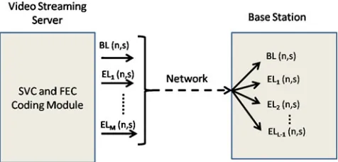
Fig. 1 Delivery architecture: from the video server to a base
station
for transmission and their associated rate, plus the amount of additional FEC protection to be scheduled
for each layer.1
5 Architecture
In this section we present the delivery architecture.
Starting from the left side of Fig.1, we consider a video
encoded in H.264/SVC format at the streaming server. The quantization points, hence the encoding rates, and the number of quality layers, the GOP (Group of Pic-ture) size and the frame rate of the video are selected a priori inside the SVC and FEC coding module. The ad-ditional packets provided by the FEC(n,s) redundancy inside the coding module increases the robustness of the video layers against channel erasures and is set high enough to allow the users to recover from losses in the worst channel conditions. At this stage the encoded video to be streamed is made of as many sub-streams as the number of quality video layers specified at the server, with additional FEC redundancy to be sent alongside with the original video packets. The video stream then is transmitted through the core network to the base station(s). A base station, when receiving the stream, extracts and buffers the sub-streams (quality video layers) with the corresponding FEC redundancy. Based on the broadcast channel feedback messages, i.e. packet erasure rates experienced by the users and available broadcast channel capacity, the base station performs the selection of the MC scheme and the amount of AL-FEC protection for each sub-stream
that is scheduled for transmission (Fig. 2). Terminals
with bad channel conditions (low SNR values) can successfully receive only packets sent with low order
1Due to lack of space, we do not formalize this algorithm in
Fig. 2 Delivery architecture: from a base station to a set of end
users
MCs, while users with good channel conditions can decode packets sent also with higher MCs. Low channel rates require more time to transmit the video packets, thus the channel capacity is eventually reached before the transmission of all the video layers. High channel rates allow to transmit the video layers and the FEC redundancy, requiring lower channel capacity. How-ever, the drawback stands in the fact that users with bad channel condition cannot benefit from such high order transmission schemes. Thus, the base station is in charge of selecting the most suitable combination of MCs to be used for sending the video layers so that to minimize the overall video distortion perceived by the set of end users participating in the video streaming session.
6 Simulation results
6.1 Simulation setup
As shown in Fig. 1, the news_qci f video sequence
is encoded at the server in H.264/SVC format, using
the JSVM software [13]. The quantization points are
selected so that the base layer (BL) is sent with rate (at the application layer) of 80 kbps, the first and the second enhancement layer are sent with rate 100 (EL1) and 160 kbps (EL2), respectively. The amount of FEC redundancy to be provided at each video layer is computed on a per GOP-basis, where the GOP size is set to 16 and a GOP is composed of one I frame and 15 P frames. The frame rate is set to 30 frames
per second.λ, the video sequence dependent constant
Table 1 MCs available at the base station
MC Scheme Mapping function
f(.)(b/symbol)
1 QPSK 1/8 0.25
2 QPSK 1/4 0.50
3 QPSK 1/2 1.00
4 16 QAM 1/2 2.00
5 16 QAM 1/3 2.67
6 64 QAM 3/5 3.60
to be used to compute the video distortion (MSE) in
our experiments, is set to 354.8 [14]. Table1presents
the set MC of MCs that can be used to transmit the
video layers at the base station, along with their channel
capacity mapping function f(.). The function is
ex-pressed as a multiplication factor from channel capacity to application rate.
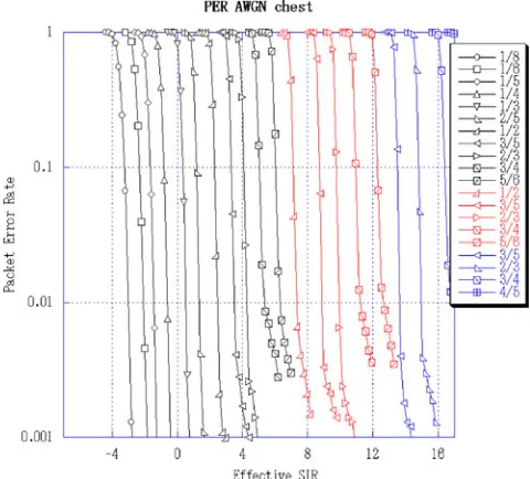
The set MC in Table 1 is a representative subset
picked from Fig. 3, which presents the user PER for
multiple MC schemes, at various SNR levels, in a LTE static scenario with an AWGN channel. In order to take user mobility and channel time variations into
account, starting from the data in Fig. 3, we derive
error probabilities for the users for their operational
MC scheme as discussed in Section3.
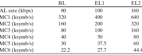
We map each video layer rate to the channel rate
of the selected MCs in Table 2. Hence, we present
the amount of symbols per second required by each transmission scheme to send the base layer and the two enhancement layer into the channel; the
conver-Fig. 3 User PER as a function of SNR for different MCs from
Table 2 Application and channel rates for the H.264/SVC video
sent with MCs in Table1
BL EL1 EL2
AL rate (kbps) 80 100 160
MC1 (ksymb/s) 320 400 640
MC2 (ksymb/s) 160 200 320
MC3 (ksymb/s) 80 100 160
MC4 (ksymb/s) 40 50 80
MC5 (ksymb/s) 30 37.5 60
MC6 (ksymb/s) 22.2 27.7 44.4
sion from application layer rate (kbps) to channel rate (ksymb/s) for each MC is computed based on the bits–
to–symbol factor in Table1.
6.2 Impact of user distribution and channel capacity
In this section we investigate the impact of the user dis-tribution when varying the maximum channel capacity
according to the video rates in (Table2). We consider a
base station broadcasting the video stream to N=100
users, with user distributions as reported in Table3. In
our experiments we use three user distributions: left, i.e. most of the users can successfully decode packets only if sent with low order MCs (e.g., most users are considered to be far from the base station, hence they experience a low SNR), middle, i.e. most of the users can decode packets only if sent with MCs in the middle of the set or lower, right, i.e. most of the users can decode packets sent with high order MCs (e.g., most users are close to the base station and experience good SNR levels). The cumulative distribution of users that
benefit from the use of any MC is reported in Table3.
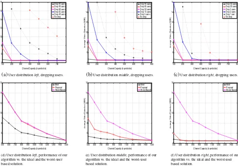
Next, we show the performance of our heuristic algorithms, for each user distribution. We explore the cases when the base station optimizes the transmission of the base layer at the expense of dropping some of the
users (Fig.4a–c), and when it decides to serve all users
with minimum video quality at least, e.g., fix the MC of
the base layer to the lowest MC inMC (Fig.4d–f). In
the plots we show the system average video distortion (MSE), i.e. the average of all individual distortions perceived by the clients, while varying the channel
capacity. Given the channel rates in Table2, we span
Table 3 User distributions MC Left Middle Right
1 100 100 100
2 60 95 99
3 35 85 98
4 20 50 95
5 10 15 80
6 5 5 50
the channel capacity region of [100–800] ksymb/s when the base station might take the decision to drop users with weak channel conditions, and the region [500– 1,500] ksymb/s when all users are served. We compare our proposal to a worst-user based solution, when the base station prioritizes the worst user in the cell, and to an ideal case where each user can be served with a single unicast stream with the same capacity of the broadcast channel. Thus, the ideal case can be seen as a multiple unicast streaming session, where each single unicast channel has the same channel capacity of the broadcast channel, without being shared among users.
Starting with the analysis of Fig.4a–c, dropping users
belonging to lower order MCs is clearly beneficial in terms of overall video distortion (normalized on the number of effective receivers), with striking gains when
most of the users can decode higher MCs (Fig. 4c).
The decrease in distortion is smoother when users are
distributed uniformly (Fig. 4b) and when a large set
of users receives at lower order MCs (Fig. 4a). Each
curve starts from a channel capacity that depends on
the channel rates of each MC, as specified in Table2.
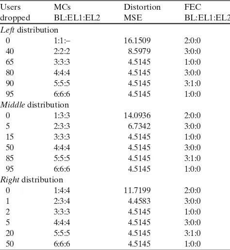
E.g., 400 ksymb/s is the minimum channel capacity for serving all users so that to meet the requirement of sending the whole base layer at MC1 with additional FEC packets. However, it is important to consider both the impact in terms of MSE gained and the number of users dropped when the base station might decide to discard users, and where the trade-off strictly depends on the requirements of the streaming application. Thus, we report in the legend of the plots the number of users dropped by the base station, in order to em-phasize that the action taken to decrease the overall distortion comes with a cost in terms of number of users discarded. A more detailed prospect is provided
in Table 4, where the channel capacity is fixed at
400 ksymb/s, and the average video distortion achieved when dropping users is reported with the amount of users discarded. Moreover, to complete the picture, we report the FEC required per GOP for each combina-tion of MCs.
We next discuss Fig. 4d–f, i.e. when all users are
served by the base station. As expected, when most of
the users can be served with low order MCs (Fig.4d),
our algorithm sticks to the performance of the worst-user based solution. In fact, among all the possible combinations of MCs, the algorithm selects constantly MC1 for sending all the video layers, as shown in
Table 5. This is due to the fact that only a small set
of users can benefit from the use of higher order MCs, thus the overall amount of distortion strictly depends on the majority, i.e. users successfully receiving with
100 200 300 400 500 600 700 4
6 8 10 12 14 16 18
Channel Capacity (k symbols/s)
Average Video Distortion (MSE)
Drop 95 users Drop 90 users Drop 80 users Drop 65 users Drop 40 users No drop
(a) User distribution left, dropping users.
1004 200 300 400 500 600 700 800 6
8 10 12 14 16
Channel Capacity (k symbols/s)
Average Video Distortion (MSE)
Drop 95 users Drop 85 users Drop 50 users Drop 15 users Drop 5 users No drop
(b) User distribution middle, dropping users.
1004 200 300 400 500 600 700 800 6
8 10 12 14 16
Channel Capacity (k symbols/s)
Average Video Distortion (MSE)
Drop 50 users Drop 20 users Drop 5 users Drop 2 users Drop 1 user No drop
(c) User distribution right, dropping users.
5004 600 700 800 900 1000 1100 1200 1300 1400 1500 6
8 10 12 14 16
Channel Capacity (k symbols/s)
Average Video Distortion (MSE)
Ideal Proposal Worst-Based
5004 600 700 800 900 1000 1100 1200 1300 1400 1500 6
8 10 12 14 16
Channel Capacity (k symbols/s)
Average Video Distortion (MSE)
Ideal Proposal Worst-Based
5004 600 700 800 900 1000 1100 1200 1300 1400 1500 6
8 10 12 14 16
Channel Capacity (k symbols/s)
Average Video Distortion (MSE)
Ideal Proposal Worst-Based
(f) User distribution right, performance of our algorithm vs. the ideal and the worst-user based solution.
(d) User distribution left, performance of our algorithm vs. the ideal and the worst-user based solution.
(e) User distribution middle, performance of our algorithm vs. the ideal and the worst-user based solution.
Fig. 4 Impact of user distribution and channel capacity. Average video distortion (normalized on the number of effective receivers)
vs. channel capacity
can choose to drop a percentage of users so that to serve only the best users with a significantly improvement in terms of video distortion, but at the cost of discarding a high percentage of users. As soon as users are more
uniformly distributed in terms of MCs (Fig. 4e), by
using our algorithm the overall video distortion drops towards the ideal case, sticking to it when users are
mostly using higher order MCs (Fig.4f), from channel
capacity 600 ksymb/s. The overall progression of our al-gorithm with respect to the selection of the MCs to use for sending the video layers for each user distribution,
when all users are served, is also reported in Table5.
With user distribution left the algorithm keeps using MC1 for streaming the video, while with distribution
middle and right the algorithm keeps MC1 for sending
the base layer, so that to serve the users with worst channel condition with the base video quality. Higher order MCs are selected for sending the enhancement layers, so that to provide higher video quality to the users with good channel condition. At a channel capac-ity above 1,500 ksymb/s, according to our scenario, all
the video layers can be sent with MC1, without being truncating, together with the additional FEC packets. Regarding the amount of FEC required when selecting
the combinations of MCs in Table 5, only the base
layer is protected with two redundant packets per GOP (FEC(18,16)). This is also due to the relatively low packet error rate that we consider for the users, and is
in line with our previous results reported in [14].
6.3 Comparison with AVC-based solutions
6.3.1 QCIF video
Table 4 Best combinations of MCs, MSE and amount of FEC
when dropping users, channel capacity 400 ksymb/s
Users MCs Distortion FEC
dropped BL:EL1:EL2 MSE BL:EL1:EL2
Left distribution
0 1:1:– 16.1509 2:0:0
40 2:2:2 8.5979 3:0:0
65 3:3:3 4.5145 1:0:0
80 4:4:4 4.5145 3:0:0
90 5:5:5 4.5145 3:1:0
95 6:6:6 4.5145 1:0:0
Middle distribution
0 1:3:3 14.0936 2:0:0
5 2:3:3 6.7342 3:0:0
15 3:3:3 4.5145 1:0:0
50 4:4:4 4.5145 3:0:0
85 5:5:5 4.5145 3:1:0
95 6:6:6 4.5145 1:0:0
Right distribution
0 1:4:4 11.7199 2:0:0
1 2:3:4 4.4583 3:0:0
2 3:3:3 4.5145 1:0:0
5 4:4:4 4.5145 3:0:0
20 5:5:5 4.5145 3:1:0
50 6:6:6 4.5145 1:0:0
Starting with the analysis of QCIF video sequences, three copies of the same video stream are built based on H.264/AVC from the same QCIF video sequence considered above, so that the encoding rates are 80, 240 and 340 kbps, respectively. We set the channel capacity to 500 ksymb/s, and we let the base station select which MC to use to broadcast the three bitstreams so that to meet the channel constraint and to provide the mini-mum overall video distortion. Making sure that all the users at least can get the first bitstream (80 kbps), the remaining channel capacity can be allocated to transmit in parallel a second bitstream (240 kbps) and eventually a third bitstream. This means that the base station will store multiple copies of the same video stream (additional storage and capacity cost) and each user will
Table 5 Best combinations of MCs for each user distribution, all
users served
Channel Left Middle Right
(ksymb/s) BL:EL1:EL2 BL:EL1:EL2 BL:EL1:EL2
500 1:1:– 1:3:3 1:4:4
600 1:1:– 1:3:3 1:3:4
700 1:1:– 1:3:3 1:3:3
800 1:1:1 1:3:3 1:3:3
900 1:1:1 1:1:3 1:3:3
1000 1:1:1 1:1:3 1:3:3
1200 1:1:1 1:1:2 1:3:3
1500 1:1:1 1:1:1 1:1:1
Table 6 Comparison with AVC, channel capacity 500 ksymb/s,
average MSE
MCs MSE MSE MSE
1st:2nd:3rd left middle right
AVC 1:4:– 15.81 12.52 7.58
AVC 1:5:6 16.78 16.23 7.96
AVC 1:6:6 17.33 17.33 11.25
SVC 1:(1,3,4):(–,3,4) 14.10 8.95 6.12
play only the best stream that fits its channel condition.
In Table 6 we report three bitstream-switching
solu-tions based on H.264/AVC and one solution based on H.264/SVC for the mentioned setting, varying the user distribution.
The bitstreams (AVC) or quality layers (SVC) are sent with MCs reported in the second column of the table as first, second and third video stream (for the SVC solution, EL1 and EL2 are sent with MCs 1 for user distribution left, 3 for the middle and 4 for right one). From the table we draw the conclusion that send-ing one scalable stream provides in average a better video quality, due to the more efficient usage of the channel capacity. Sending multiple AVC streams re-duces the number of solutions that can be used to meet the channel constraint, which moreover leads to further increasing the number of users receiving a stream with lower video quality than expected. Similar results were obtained for different settings, and are omitted here due to space constraints.
6.3.2 CIF video
We now encode the News_ci f and Foreman_ci f yuv
video sequences in H.264/AVC and SVC format. The quantization points selected for each video quality layer (SVC) and for each bitstream (AVC), the correspond-ing cumulative encodcorrespond-ing rates and the ideal MSE
per-Table 7 Quantization points, rates, and ideal MSE for each
quality layer (SVC) or bitstream (AVC) of Foreman and News
Layer Q point Rate (Kbps) MSE
Foreman_yuv
Base 42 117.1 65.8810
Enh. 1 32 402.5 21.5894
Enh. 2 22 1,506.3 5.4863
AVC 1 42 117.3 61.5858
AVC 2 33 317.8 20.6667
AVC 3 22 1,375 5.1209
News_yuv
Base 42 90.4 44.9946
Enh. 1 32 291.9 11.8119
Enh. 2 22 846.8 2.7682
AVC 1 42 91.2 41.7206
AVC 2 33 230.5 11.5385
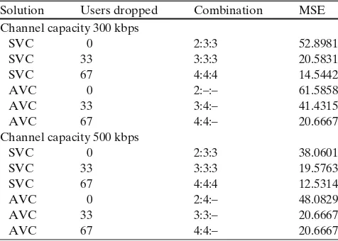
Table 8 Best combinations of MCs for the Foreman, comparison
between AVC and SVC solutions, users uniformly distributed Solution Users dropped Combination MSE Channel capacity 300 kbps
SVC 0 2:3:3 52.8981
SVC 33 3:3:3 20.5831
SVC 67 4:4:4 14.5442
AVC 0 2:–:– 61.5858
AVC 33 3:4:– 41.4315
AVC 67 4:4:– 20.6667
Channel capacity 500 kbps
SVC 0 2:3:3 38.0601
SVC 33 3:3:3 19.5763
SVC 67 4:4:4 12.5314
AVC 0 2:4:– 48.0829
AVC 33 3:3:– 20.6667
AVC 67 4:4:– 20.6667
ceived by correctly receiving each layer is reported in
Table7for both video sequences.
For the analysis of CIF video sequences, for the ease of implementation, we restrict the set of available modulation and coding schemes to MC2, 3 and 4. More-over, we assume that users are uniformly distributed, i.e. 1/3 of the users can only decode MC2, another 1/3 of the users can decode both MC2 and MC3, and the remaining 1/3 of users can decode MC2, MC3 and MC4.
In Table 8, we provide the best combinations of
MCs selected for the Foreman video sequence, for both AVC and SVC, and channel capacity set to 300 and 500 kbps. With the increase of channel capacity, SVC allows to gradually increase the average MSE in case all users are served. A similar effect is observed when part of users is dropped in order to enhance the video quality perceived by users with better channel conditions. With AVC, the channel capacity is a severe constraint, as it
can be seen in Table 8. Here, for instance, when 67
users are dropped, the average MSE does not benefit from the increase of the channel capacity from 300 to 500 kbps.
7 Discussion on practical issues
In the previous sections we detail our proposal for a wireless broadcast system for scalable video stream-ing. Our evaluation concentrates on emphasizing the theoretical characteristics of this system, and simulate its behavior. Our conclusions open the discussion for more practical issues which must be evaluated in the case of a real deployment of our proposal. We first discuss the problem of evaluating the coverage area of the MCs in use in the broadcast system. When a
MC scheme is selected for video broadcast, we implic-itly shape the maximum size of the cell in which the broadcast can be successfully received. Field informa-tion on the placement and coverage area of the base stations of a cellular operator offering such a service leads to a better analysis of the trade-offs involved. In this perspective, realistic user density models, path-loss models and SNR levels give the information needed for designing an efficient broadcast system. Thus, we can select and eventually adapt our appropriate transmis-sion strategy. To increase the value of the presented simulation results from a practical point of view, we compute the SNR value for a range of mobile locations with an LTE system level simulation tool. A look-up table is generated by link level simulations and used for
system level simulations as in [17, 18], where at each
SNR level entry corresponds to a given FER (Frame Error Rate). We run simulations on an LTE system assuming perfect channel knowledge at the receiver. In order to compute the distance of the users from the base station (i.e. to evaluate the coverage area of a MC), we use a simple distance-dependent path loss model (instantaneous channel variations, e.g. fading, are not considered):
Pploss=128.1+37.6log10(r) (2)
where Plossis the path loss in dB and r is the distance in
Km between the mobile user and the base station. We assume a carrier frequency of 2 GHz, a transmission bandwidth of 10 MHz, an inter-site distance (ISD) of
500 m, a transmission power (Ptx) of 46 dBm, a
penetra-tion loss (Ppen) of 20 dB, a noise figure (PNfigure) of 9 dB
and a thermal noise (Pthermal) density of−174 dBm/Hz.
Assuming the received signal power at the user side:
Prx =Ptx−Ppen−Pploss= −102.1−37.6log10(r)dBm
(3)
and the following noise power:
Pnoise=Pthermal+PNfigure= −95dBm; (4)
the final relation between SNR and distance r is as follows:
SNR=Prx−Pnoise= −7.1−37.6log10(r). (5)
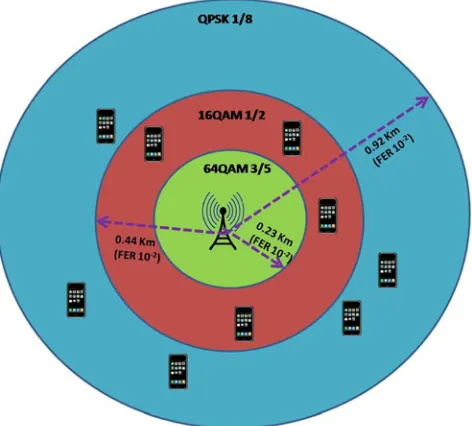
For instance, if we select QPSK 1/8 and we target an
FER of 10−2, which corresponds to an SNR level of
−5.7 in the look-up table, then the distance r of a
mobile user from the LTE base station is0.92 km. We
Fig. 5 Lower orders of MC (e.g. QPSK1/8) allow to cover larger areas, and thus larger sets of users. To note that the coverage area of QPSK1/8 includes the coverage areas of 16 QAM1/2and 64 QAM4/5. Same applies to the coverage area of 16 QAM1/2, which includes the coverage area of 64 QAM4/5
potential MCs. Further open issues to be evaluated in case of real deployment are summarized as follows:
• Number of users served/number of base stations
involved: The broadcast decisions taken by our algorithm influence the total number of users that can decode the broadcast stream. For higher MC schemes, only the users with the better SNR levels, hence closer to the base station, are able to decode the video information. Hence, for coverage preser-vation, a cellular operator would have to increase the density of base stations offering this service. In-sights on the implementation and operational costs of such a deployment would bring an additional dimension to our proposal.
• Different video scalability dimensions: In our
analysis we only consider the SNR scalability fea-ture of the H.264/SVC codec. However, the spa-tial and temporal scalability features of the same codec could bring different dimensions and more flexibility to our framework. E.g., broadcasting a video stream encoded at different spatial resolu-tions would address the problem of the heterogene-ity of mobile devices in terms of screen size and resolution capabilities.
• H.264/AVC vs. SVC: While we present some
cod-ing performance results for both AVC and SVC encoders, a full comparison between the two would imply availability of low-complexity decoders in
the mobile hand-sets and backward compatibility issues.
8 Conclusions
We address the problem of wireless broadcast of a scalable video bitstream in a cellular system. We for-mulate a cross-layer framework in which we attempt to optimize the number of streamed video layers, the modulation and coding scheme, and the application layer FEC used for each layer. Our framework takes into account the total channel capacity and the indi-vidual channel conditions observed by the users. Our optimization metric is represented by the total video distortion observed by the system. In order to make the analysis of the proposed problem tractable, we de-couple the influencing factors, and we provide heuristic algorithms for each of the individual sub-problems. We test our proposed method for different channel scenarios and user distributions, and we compare our scalable solution with baseline algorithms and with a traditional broadcast system based on AVC encoding. We observe the better results obtained by our proposed algorithms, due to the extra flexibility offered by the scalable application paradigm and due to the cross-layer approach. Finally we explore further issues and problems that influence a practical deployment of our solution from the point of view of a mobile operator.
Acknowledgements We would like to thank our colleague Kat-sutoshi Kusume for the valuable discussions and for his help on the LTE-based simulation environment.
References
1. 3GPP (2006) Introduction of the multimedia broad-cast/multicast service (MBMS) in the radio access network (RAN)
2. 3GPP specification detail: MBMS (2010) [Online]. Available: http://www.3gpp.org/ftp/Specs/html-info/26346.htm
3. Schwarz H, Marpe D, Wiegand T (2003) Overview of the scalable video coding extension of H.264/AVC. IEEE Trans Circuits Syst Video Technol 17(9):560–576
4. Chan CW, Bambos N, Wee S, Apostolopoulos J (2008) Wire-less video broadcasting to diverse users. In: IEEE ICC 2008, Beijing, China, pp 377–382
5. Shokrollahi A (2006) Raptor codes. IEEE/ACM Trans Netw (TON) 14:2551–2567
6. Dvb: the global standard for digital television (2010) [On-line]. Available:http://www.dvb.org/
8. Mansour H, Nasiopoulos P, Krishnamurthy V (2008) Joint media-channel aware unequal error protection for wire-less scalable video streaming. In: Proceedings of IEEE ICASSP
9. Van Der Schaar M, Krishnamachari S, Sunghyun C, Xiaofeng X (2003) Adaptive cross-layer protection strategies for robust scalable video transmission over 802.11 WLANs. IEEE J Sel Areas Commun 21:1752–1763
10. Villalon J, Cuenca P, Orozxo-Barbosa L, Seok Y, Turletti T (2007) Cross-layer architecture for adaptive video multicast streaming over multirate wireless LANs. IEEE J Sel Areas Commun 25(4):699–711
11. Cohen R, Grebla G, Katzir L (2009) Cross-layer hybrid FEC/ARQ reliable multicast with adaptive modulation and coding broadband wireless networks. In: IEEE Infocom 2009, Rio de Janeiro, Brazil
12. Jurca D, Kellerer W, Steinbach E, Kahn S, Thakolsri S, Frossard P (2007) Joint network and rate allocation for video
streaming over multiple wireless networks. In: IEEE interna-tional symposium on multimedia (ISM’07)
13. Joint scalable video model—reference software (2009) [Online]. Available: http://ip.hhi.de/imagecom_G1/savce/ downloads/SVC-Reference-Software.htm
14. Munaretto D, Jurca D, Widmer J (2009) A fast rate-adaptation algorithm for robust wireless scalable streaming applications. In: IEEE WiMob 2009, Marrakech, Morocco 15. Karlsson J, Riback M (2008) Initial field performance
mea-surements of LTE. Ericsson Review
16. Nokia Siemens Networks (2009) LTE performance for initial deployments. White paper
17. 3GPP technical report 25.814 v7.1.0 (2006-09). [Online]. Available:http://www.3gpp.org/