© 2016 IJSRSET | Volume 2 | Issue 1 | Print ISSN : 2395-1990 | Online ISSN : 2394-4099 Themed Section: Engineering and Technology
Controlled SINK Mobility Clustering Protocol for Multi-Hop
Wireless Sensor Network
D. Deepika*, R. Prabha
Department of Electronics and Communication Engineering, SNS College of Technology, Coimbatore, Tamil Nadu, India
ABSTRACT
Sink mobility has been utilized in numerous schemes to prolong the lifetime of wireless sensor networks (WSNs). Among the many ways of improving the performance of a WSN in terms of crucial metrics such as its lifetime and data latency, utilizing the mobility of some of the network components has been recently observed to be among the most promising. Regardless of its numerous advantages, delivering of the data to the mobile sink is a challenging task for the limited resource sensor nodes. Sink mobility causes the dynamic network topology. Data delivery consumes more energy and it can be reduced using sink mobility. The mobility of sink causes regular updating of its location in order to deliver the data packets. Here controlled sink mobility is used for the path routing of mobile sink and the parameters like energy efficiency, control overhead, data delivery rate are simulated and compared with existing uncontrolled sink mobility.
Keywords: Wireless Sensor Networks, Sink mobility, Data latency, Network Lifetime.
I.
INTRODUCTION
Wireless Sensor Network (WSN) is an adhoc distributed sensing sensor network that collects detailed information about the environment. These networks are largely deployed and are used in many dangerous environments. The sensor nodes are battery energized and limited energy. The sensor node monitors the environment and reports the information to a base station or sinks periodically so that the information can be further processed. Energy-hole problem arises when the sink is static. Sink mobility has been introduced to balance the node’s energy dispersion. The sink mobility also connects the isolated network segments when there is a need. Several applications naturally require the sink mobility e.g., in a battlefield environment a real-time data can be obtained about the interruption of enemies and their activities. Similarly in a disaster, sink mobility is required in a sensor field; a rescuer with a PDA can be let free to move around the disaster area in search of any residues. In an ITS (Intelligent Transport System), the sensor nodes provides prior warnings to the drivers about the physical approach of any danger.
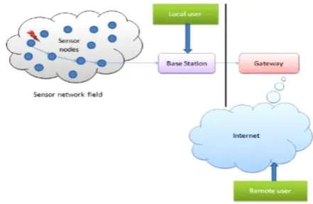
Figure 1. Basic Wireless Sensor Network Architecture.
updates about the mobility of sink must be avoided because of the scarce energy resources since it opposes the goal of energy conservation. To eliminate the problem and to enable the nodes to maintain the fresh routes towards the latest position of the mobile sink with minimum communication cost, virtual infrastructure over the physical network is taken as an efficient approach. Only a crew of designated nodes in the sensor field is used to keep track of the location of the sink. Introducing sink mobility in the network will have advantages like sensor lifetime enhancement, improved coverage, improved throughput and data fidelity and improved security.
II.
METHODS AND MATERIAL
A.
Literature ReviewSink mobility is considered as an efficient technique to improve the network's lifetime as it give preference to the residual energy of the nodes. For increasing the network lifetime, not only the energy consumption by the nodes is important and the balanced energy consumption among all the sensor nodes [4]. The conventional way of reporting the event to some static sink involves multi-hop or single-hop communication. This method will consumes more energy and the energy will deplete quickly and leads to hot-spot problem. To overcome this issue a concept called mobile sink is introduced. And also some applications voluntarily requires sink mobility (e.g.) A farmer has to know which part of the field need water fertilization.
Sink Mobility Patterns in WSN
The three basic mobility patterns that a mobile sink exhibit in sensor field are
1. Random/ unpredictable mobility pattern:
Here the mobility pattern is unpredictable regarding the future position of sink.
2. Predictable/Fixed-Path mobility pattern:
The mobility pattern follows a certain fixed path like along the periphery of the sensor field, thus can learn the expected time of visit of sink at particular location.
3. Controlled Mobility pattern:
The mobility pattern of the sink is controlled by the observer.
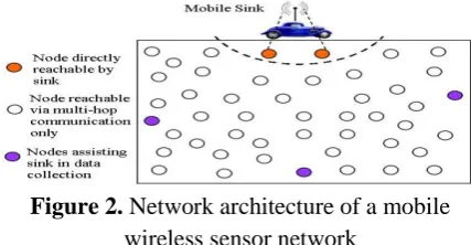
Figure 2. Network architecture of a mobile wireless sensor network
i. Performance Measures Of Sink Mobility
Sink is considered as an important parameter to increase the performance of the network in terms of lifetime and data latency. The paper shows a tradeoff between lifetime and data latency using controlled sink mobility by network conditions. Data MULE kind is considered for uncontrolled mobility with single-hop and is compared with GMRE controlled sink mobility with multi-hop paths. The comparison is made into three parts, one is number of MULEs, second is nodal buffer size, and third is area size. The results proved that increase in MULE will reduce the data latency whereas it is comparatively high while considering GMRE method. The packet delivery ratio is high in case of uncontrolled sink mobility whereas network lifetime is increased in case of controlled sink mobility.
ii. Hierarchical Clustering Protocol
The paper contributes sink mobility to increase the network lifetime of hierarchical routing protocols. Here it compares two scenarios; the first is to implant static sink and later one to mobile sink. The performance parameters compared between two scenarios are number of alive nodes, number of dead nodes and throughput. The parameters are compared between four routing protocols namely Low Energy Adaptive Clustering Hierarchy(LEACH), Threshold Sensitive Energy Efficient Sensor Network(TEEN), Distributed Energy Efficient Clustering(DEEC) and two variants of TEEN namely Clustering and Multi-hop Protocol in Threshold Sensitive Energy efficient Sensor Network(CAMPTEEN) and Hierarchical Threshold Sensitive Energy Efficient Sensor Network(H-TEEN).
iii. Sink Mobility Based Energy Efficient Routing
Sink mobility is considered as efficient technique to balance the energy among all nodes. The paper considers a scenario where both the nodes and sink node has to keep track of the locations of each since both are mobile. The work considers network lifetime as important parameter and proposed shortest route towards sink for data transfer by maintaining energy consumption among the nodes. The scenario considered here is under uncontrolled sink mobility with proper election of CH’s to balance the energy among the nodes. In uncontrolled sink mobility where the mobility is unpredictable, the nodes has to keep track of its new location and transmits the data if it is inside the range of mobile sink else it uses Euclidian distance to find shortest path for mobile sink in order to route the data. The conclusion was made that energy consumption is reduced compared to previous methods and mobility of nodes in entire network as to be considered.
iv. Sink Mobility Patterns
Sink mobility exploits to prolong the network lifetime but it results in data delivery latency and reliability caused due to dynamic network topology. To mitigate these effects either multiple mobile sink should be employed or explicitly controlling the mobility of sink to reduce multi-hop communication in data delivery or deploying super nodes with rich energy.
Employing multiple mobile stations will need tight collaboration among them. In case of controlled sink mobility harvesting data delivery in less time is not viable in case of harsh environment. Employing super nodes is against the rule of WSNs.
Incorporating cluster-based data dissemination together with mobility-aware duty-cycle mechanisms will optimize the trade-off between energy consumption by the nodes and data delivery latency that to improves the packet delivery ratios also.
B.
Proposed SystemThe work aims to optimize the trade-off between energy consumption and data delivery latency using mobile sink based WSN. A virtual backbone structure is constructed
which partitions the sensor field into virtual grid of equal sized cells. The goal behind virtual structure is to minimize the route readjustment cost which causes quick updating of sink current location so that data can be efficiently delivered [5].
The controlled sink mobility is employed as it reduces the data delivery latency compared to other sink mobility patterns [2]. H-TEEN protocol is employed for clustering as it increases the network lifetime and also outperforms with controlled sink mobility compared to other protocols [3].
The parameters taken in account are throughput, packet delivery ratio and energy consumption.
i. Virtual Structure Construction
The VGDRA scheme constructs the virtual grid structure by first partitioning the sensor field into several uniform sized cells based on the number of nodes in the sensor field. The rationale behind such portioning is to uniformly distribute the work-load on part of cell-header nodes which consequently results in prolonged network lifetime.
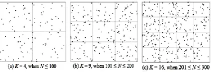
Figure 3: Example of different virtual grid based structures for different number of nodes
To determine the optimal number of cells and thus the cluster-heads, adopt the heuristics used in HEED which consider 5% of the total number of sensor nodes. Given N number of nodes, the VGDRA scheme partitions the sensor field into K uniform sized cells using Equation 1, where K is a squared number.
After the network partitioning, next VGDRA scheme appoints a set of nodes as cell-headers. Initially in every cell, the node closest to the mid-point of the cell is elected as the cell-header. Nodes using the knowledge of sensor field’s dimension and the total number of nodes compute the midpoints of all the cells. In order to reduce the communication cost in the cell-header election, only those nodes take part in the election whose distance to the mid-point of the cell is less than a certain threshold. The threshold distance to the mid-point is gradually increased if no node can be found within the threshold distance around the mid-point of the cell. This threshold based cell-header election strategy not only helps in energy conservation but also elects the cell-header at the most appropriate position within the cell. After the initial cell-header election, each cell-header notifies its status not only to the surrounding nodes within its cell but also to the nodes which are slightly beyond the cell boundary. Nodes might receive cell-header notifications from more than one cell-header and associate themselves to the closest one. Nodes that receive notifications from multiple cell-headers also share the information of the secondary cell-header with their primary cell-header. In this way, each cell-header form adjacencies with neighboring cell-headers using gateway nodes. The maximum number of adjacent cell-headers for a borderline cell-header is 3 whereas for an inside cell-header is 4. The set of cell-header nodes together with the gateway nodes constructs a chain like virtual backbone structure as shown in Fig.3.2.
Figure 4: An example of virtual backbone structure after establishing adjacencies.
After the cell-header election and establishing the adjacencies, communication routes are setup considering the mobile sink is located at coordinates (0, 0). As a result of the initial routes setup, all the cell-headers
adjust their routes to the initial position of the mobile sink. Fig.8 shows the virtual backbone structure after the initial routes setup when the sensor field is partitioned into 16 cells.
III. RESULTS AND DISCUSSION
SIMULATION AND RESULTS
The clustering technique was implemented using H-TEEN protocol. The cluster head selection is mainly based on the two parameters. One is the distance from the centre of the grid and other is the residual energy of the node. Since here consideration is homogeneous network, all the nodes have the capability and chance to become a cluster head.
Figure 5: Clustering Technique
In the figure 5. The various colors represent the different nodes belonging to different cluster. It also shows that node 1 is the source node which wants to transmit the data to the sink.
The packet delivery ratio is calculated based on considering the total number of packets transmitted and number of packets delivered to the destination.
*100
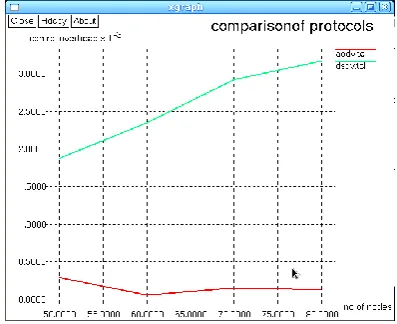
Figure 6 shows the PDR output for 50,60,70,80 nodes. The output shows the PDR values for controlled and uncontrolled sink mobility. The idea delivered by the graph is that as in controlled sink mobility sink moves accordingly depending on the traffic in the cell the packets are delivered properly with minimum loss.
Figure 7: Power delivery ratio
Figure 7 shows the control overhead measurements of the proposed system. The control overhead includes the query packets, packet sequence number, routes to route the packet to the destination, the next hop and neighborhood details, etc.
Though the overhead packet helps in routing it reduces the efficiency of data transfer as it accommodates in the data packets. The amount of useful information reduces as control overhead increases.
Figure 8: Control Overhead
Figure 8 shows the energy consumption by the nodes in data transmission. The energy consumption during transmission includes sensing the sink location and
querying and then actual data transfer. Energy consumption will be more in communication process only. The graph delivers that energy consumption of proposed system is less compared to the existing one.
Figure 9: Energy consumption
Figure 9 .shows the End-to-End delay of the packets. Delay parameter causes serious threat to the efficiency of the network in case if it increases the PDR will reduces which in turn increases the packet loss.
Figure 10: End-to-End delay
From the above, it is analysed that controlled sink mobility acts according to the data traffic ratio in the locations. This will increase the packet delivery ratio and reduces the loss. The parameter show abrupt changes in the values in case of different number of nodes considered.
IV. CONCLUSION
In this paper, a study on sink mobility patterns and protocols that performs better with sink mobility are done. The conclusion made after the study is, for applications that requires high packet delivery ratio with reduced latency can employ controlled sink mobility. And also comparing to other protocols H-TEEN performs better with controlled sink mobility.
A virtual structure is employed to reduce the energy consumption by the nodes and also the parameters like energy consumption, control overhead, and packet delivery ratio are compared with the existing one and the simulation shows that the controlled sink mobility is better than uncontrolled sink mobility pattern.
V.
REFERENCES
[1] Khan A.W., Abdullah A. H., Anisi M. H., and et al., 2015:”VGDRA: ‘A Virtual Grid-Based Dynamic Routes Adjustment Scheme for Mobile Sink-Based Wireless Sensor Networks’, in IEEE sensors journal, vol. 15, no. 1.
[2] Khan A.W., Abdullah A. H., Anisi M. H., and et al., 2014: ‘A comprehensive study of data collection schemes using mobile sinks in wireless sensor networks’,in IEEE Sensors journal (Basel, Switzerland), vol. 14, pp.
[3] Javid N., Ain Q., Khan M.A, et. Al., 2009: ‘On Sink Mobility Trajectory in Clustering Routing Protocols in WSNs’.
[4] Stefano Basagni, Alessio Carosi and et al., 2010:’Controlled Vs. Uncontrolled Mobility in Wireless Sensor Networks: Some Performance Insights’.
[5] Azrah Shabeen, Savitha.S, 2015:’Energy Efficient Routing Technique in Mobile Sink Based WSN using VGA’, IJRCAR Journal, Vol.3 Issue.5. [6] Khan, M.I., Gansterer W.N., Haring G., 2007:
‘Congestion avoidance and energy efficient routing protocol for wireless sensor networks with a mobile sink’. J. Netw., 2, 42–49.
[7] Kansal, A., Somasundara, A.A., Jea, D.D., Srivastava, M.B.; Estrin, D., 2004: ‘Intelligent Fluid Infrastructure for Embedded networks’, Proceedings of the ACM, 2nd International
Conference on Mobile Systems Applications, and Services, Boston, MA, USA, 6–9; pp. 111–124. [8] Denkovski, D.; Mateska, A.; avrilovska, L., 2010:
‘Extension of the WSN Lifetime through Controlled Mobility’, In Proceedings of the Seventh IEEE International Conference on Wireless On-Demand Network Systems and Services (WONS), Kranjska Gora, Slovenia, 3–5 , pp. 151–156.
[9] Schurgers, C., Tsiatsis, V., Ganeriwal, S., Srivastava, M., 2002: ‘Optimizing sensor networks in the energy-latency-density design space’, IEEE Trans. Mob. Comput. , 1, 70–80.