Integration of the ST Language in a Model-Based
Engineering Environment for Control Systems – An
Approach for Compiler Implementation
Elisabete Ferreira1, Rogério Paulo1, Daniela da Cruz2 and Pedro Henriques2
1EFACEC Engenharia S.A., Maia, Portugal 2Universidade do Minho, Braga, Portugal
Abstract. In the context of the INTEGRA project, compilation and code generation features for behavior definition are to be integrated in an existing model-based engineering environment for control systems. The devised compiler architecture is domain-specific and provides support for multiple input languages and multiple target platforms. In this paper we discuss an architectural approach in which the compiling process is organized in two different stages: the compiling stage and the linking stage. The compiling stage generates target independent code from possibly multiple input languages. The linking stage assembles pre-compiled code modules and generates a target specific executable code for a given virtual machine. To be more specific this paper describes the integration of the ST language in the tool core meta-model and the ST compiler is presented as an application case study.
Keywords. Code Compiler, Linker, C#, ANTLR, ASML, IEC 61131-3 ST.
1. Introduction
The INTEGRA [8] project is an industrial R&D project developed by EFACEC in collaboration with REN1 and some universities, such as UP2 and UM3. This project involves the development of a prototype for a command, control and
protection system for substations based on the new standard protocol for
communications.
The main objectives of the INTEGRA project were: to evaluate the application of international standards in substation automation systems; to confirm interoperability between devices from different manufacturers; to develop embedded real-time devices for substation automation systems; and
1 REN – Rede Eléctrica Nacional, is responsible for the uninterrupted supply of electricity and natural gas in Portugal.
to integrate engineering tools. The project also includes a demonstration system installed in a transmission substation near Lisbon.
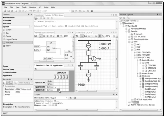
The purpose of the project described in this paper, developed in the context of the INTEGRA project, is to integrate compilation and code generation features for behavior definition in an existing model-based engineering. This computer aided engineering tool, shown in fig. 1, is a specific graphical toolset aimed at integrated configuration and management of distributed control systems for power systems automation.
Fig. 1. The user interface of the engineering tool
In order to maximize user productivity the development and compilation tools are to be seamlessly integrated within the core meta-model on which the toolset is based and within the engineering environment itself. The compiler architecture to be built should lend itself to support multiple input languages and multiple target platforms in the same environment.
Traditionally a compiler is a standalone, non-interactive (batch), program that takes as input a program, written in an High-Level Programming Language, and generates as output another program with the same meaning but written in a Machine-Level (low level) Programming Language (usually Assembly or even ByteCode).
Representation (IR) carrying on the program's meaning; and the second one, the back-end (BE), takes that IR and generates the final machine code.
Moreover, the FE is itself structured in three layers: the lexical analyzer, the syntactic analyzer, and the semantic analyzer.
In a classic approach, the compiler is automatically generated as a whole by a tool called compilers-compiler, or compiler-generator, that takes the grammar (a translation grammar, or an attribute grammar) of the source language and writes the code for the FE and BE of the desired compiler (specified by that grammar).
So, a classic compiler processes one source language, and generates (without interacting with other programs or with the user) code for one target machine.
In the context of INTEGRA project, discussed along the paper, we are interested in producing modules for the analysis or code-generation tasks that interact with the other modules already implemented in the platform, complying with pre-defined interfaces.
In the scope of this paper the adoption of ST Language, as described in IEC 61131-3 International Standard [2] and the integration of a ST Compiler in the environment is discussed and presented as a case study for the approach above referred.
Section 2 presents the application domain. In section 3 the language meta-model on which the engineering environment is based is briefly described. In section 4 the ST language and its integration is presented. In section 5 our proposed compiler architecture is described in detail and in section 6 the compiler implemented in the INTEGRA project is briefly described. Section 7 presents the main conclusions of this work.
2. Application
Domain
This work is to be applied in engineering of distributed control systems for power systems automation. This application domain includes industrial control systems targeted at, but not limited to, (i) distribution and transmission substations, (ii) power stations (hydro, wind, etc.) and (iii) distribution networks. In such industrial systems the control, automation and protection functions are implemented in real-time autonomous systems involving cooperating intelligent electronic devices with physical process interface, various communication interfaces and user interface. The typical architecture is characterized by functional levels within a control hierarchy with mostly vertical information flows between levels and peer-to-peer communication at each control level.
ensured by program design and programming languages tend to be strongly typed and to limit code constructions such as recursion or involving dynamic memory allocation.
3.
ASML at a Glance
The Automation System Modeling Language [9] (ASML) is a key element of the engineering environment via which specific device and system models are set-up, validated and deployed by the control system engineer.
Through this language it is possible to describe complete device or system configurations including, but not limited to: (i) functionally-oriented control system object models, including input and output status, measurands, settings and controllable data, (ii) dynamic control system behavior, (iii) diagrammatical interactive user interface4, (iv) device hardware, (v) device local process interface, (vi) communication interfaces, (vii) data logging, etc.
The ASML definition is based on the OMG [10] four-layered meta-modeling infrastructure. In fact, the abstract syntax of the language is defined as an M2 [10] model, including static validation rules, and formally defined in a M3 [10] proprietary meta-meta-modeling language, similar to KM3 [11] or Ecore [12]. Several software components of the engineering toolset are generated by custom code generators using the ASML meta-model as input, as is the case of some graphical editors and model-checkers. The ASML itself is not a complete language since it lacks a specific concrete syntax. Device or system models are created and customized by the end-user with a set of text, graphical and diagrammatical editors.
Functional design within ASML should incorporate function decomposition in atomic units, behavior encapsulation with interface definition via inputs and outputs, executable algorithmic definitions and function allocation to devices.
Since the ASML is based in international standards, the languages selected for behavior definitions are to be compatible with the IEC 61131-3 standard [1], focused on programming languages for automation systems.
4. ST
Language
The IEC 61313-3 [2, 3] is an international standard which describes programming languages, both textual and graphical, for programmable controller software.
The language introduced in this paper is a textual language called Structured Text (ST), which is a high level language, similar to Pascal, Ada or C.
The standard defines about twenty elementary data:
–BOOL;
–SINT, USINT, INT, UINT, DINT, UDINT, LINT, ULINT (signed and unsigned integer data types);
–REAL, LREAL (floating point data types);
–TIME, DATE, TIME_OF_DAY, DATE_AND_TIME (time handling data types);
–BYTE, WORD, DWORD, LWORD, STRING, WSTRING;
Derived data types, such as structures, arrays and enumerations, can also be defined.
The language establishes three kind of program organization units (POU): functions, function blocks and programs. Functions are conventional procedures with parameters and return values; function blocks include both procedure and data which may be kept between invocations. The main difference between functions and function blocks is that function produce the same result if called with the same arguments and functions blocks contain both code and data which persists between invocations.
A program is a network of functions and function blocks, which is able to access external data, such as physical input/output of the programmable controller device. These units are run periodically or upon the occurrence of specific events.
Expressions in ST are typical expressions built from operators, variable/constant access and other conventional constructs which, when evaluated, yield a value corresponding to one specific data type.
Four types of statements are available in ST:
– assignments;
– conditional branches (if and case);
– loops (for, while, repeat and until);
– function block invocations;
The invocation of a function consists of the function name followed by a list of arguments. The list of arguments can take two different forms: the formal argument list or the non-formal argument list. In the formal argument list, the arguments list has the form of a set of assignments of actual values to the formal argument names. In the non-formal argument list, the argument list shall contain exactly the same number of arguments, in the exactly order as given in the function definition.
IN1
MAX IN2
IN3
MIN
MinMax
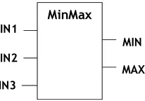
Fig. 2. Function Block MinMax external interface
To exemplify the formal and the non-formal differences in invocations consider the MinMax function block shown in fig. 2. After declaring the variable minMaxInst as an instance of function block MinMax, the next two statements in ST language are equivalents and would produce the same output values:
minMaxInst(0, 6, 4);
minMaxInst(IN3 := 4, IN2 := 6);
4.1. Integration of the ST Language in the ASML Meta-model
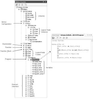
Fig. 3. UML class diagram overview of the ASML meta-model
The conditions, actions and procedures associated with functions and behavioral elements are described in ASML according to a meta-model adapted from IEC 61131-3 Structured Text [2]. Behavior units are defined as POUs which can be written in any supported language. The data typing meta-model of the ASML is common to both behavior definition and other purposes, namely for communication interface definition.
To support encapsulation and reuse of complete system behavior the ASML provides automation elements called Function Classes. A function class encapsulates an internal structure, algorithms and defines an external interface via data inputs, outputs and settings. The external interface of these classes may be defined according to user/design requirements and existing or future international standards of object models for power systems automation. Logical node classes may represent internal device behavior, communication interfaces, process interface or programmable behavior.
The ASML defines device functional structure by instantiating function classes and allocating instances in different processing units (Resources) in the physical device. Interactions between Functions and/or physical input/output of the device are defined by input/output Associations.
A small example of an ASML model is shown in fig. 4. In this example a Logical Node Class implementing a simplified alarm grouping is presented.
Function
Program
Variables Logical Node Classes
Libraries
External Interface
Logical Node Instances
Enumeration
Function Block Device Configuration
5. Compiler
Architecture
To facilitate reuse of definitions some ASML language meta-classes, such as POUs, may be defined in libraries.
Libraries contain POU external interface and pre-compiled target independent code. Therefore behavior implementation is hidden allowing some level of intellectual property protection.
5.1. Compiler Overview
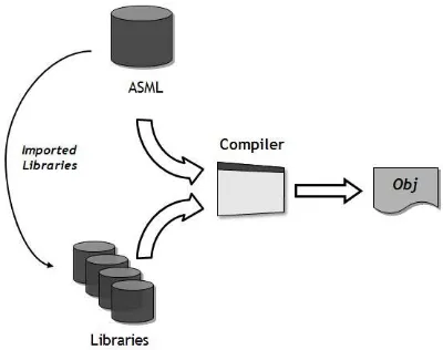
The compiling process, illustrated in fig. 5, is organized in two different stages: the compiling stage and the linking stage.
Fig. 5. The compiling process
The compiling stage illustrated in fig. 6. the compiling stage overview, is responsible to generate ObjectCode, which is target and language independent code.
Fig. 6. The Compiling Stage Overview
The compiler receives an ASML model to compile and generates an
ObjectCode module containing both pre-compiled code and additional
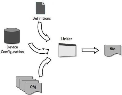
The linking stage, illustrated in fig. 7, generates target specific executable code, called ByteCode, by assembling and translating pre-compiled code included in one or more ObjectCode modules.
Fig. 7. The Linking Stage Overview
The Linker effectively generates an executable code file for a specific device. Hence the linker also receives additional data such as the device configuration and target definitions defined in the source ASML model.
The ByteCode is generated according to both the device configuration,
omitting unnecessary code, and the platform definition. Thus, the ByteCode is both target specific and platform dependent.
ByteCode files may be deployed to the corresponding device and executed
by a Virtual Machine or through other device specific means. A platform independent virtual machine is also available for device integration and direct execution of the generated ByteCode which is not analyzed in this paper.
5.2. Parser, Semantic Validator and Object Code Generator
The translation-scheme adopted to develop the compiler presented in this paper was a semantic-directed translation. With this translation-scheme each compiler component has one specific job in the compilation process. The compiling stage is organized in three components: the Parser, the Semantic
Validator and the Object Code Generator, as shown in fig. 8.
Fig. 8. Compiler Architecture
The Parser receives the POU body and instantiates the compiler
intermediate representation if the POU body is syntactical correct.
After constructing the intermediate representation all information needed for the semantic validation and translation process is produced and the source data may be discarded.
The semantic analyzer is responsible to check if the intermediate
representation of the POU body is semantically correct. The most relevant
semantic validations take place in variables, expressions and invocations.
– Each variable has a specific data type and optionally an initial value, therefore is necessary to validate if variable data type and initial value type are the same. When a variable is used in a statement is necessary to validate if the variable is accessible for the requested operation and if it is visible in the POU context.
– To validate an expression is necessary that all the operator and operand data types are compatible.
– To validate a function or function block invocation is necessary to (i) validate if the POU identifier is defined in the current ASML or in libraries, (ii) check if the invocation is allowed, for example, functions can not call function blocks, (iii) validate if the number of parameters are correct and (iv) check if the arguments data types are compatibles with the POU interface.
Once validated, the intermediate representation of all POUs defined in an ASML source can feed ObjectCode generator. The Object Code Generator is responsible to generate a list of instructions accordingly to the POU
intermediate representation.
The Object Code Generator traverses the intermediate representation and
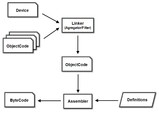
5.3. Linker and Assembler
The linking stage is organized in two components: the Linker and the
Assembler, as shown in fig. 9.
Fig. 9. Linker Architecture.
The first task of the linker is to determine which procedures (programs, functions and function blocks) must be included in the ByteCode. Then, all these procedures are included in a single ObjectCode module. If one or more procedures cannot be found the linking stage is aborted and an error is reported.
From this virtual ObjectCode module ByteCode can be generated accordingly to some target Definitions. These Definitions describe the device and the target platform, such as, byte order (little or big endian), unsupported data types and other relevant target restrictions or configuration.
The Assembler is responsible to convert that virtual ObjectCode into a
target specific ByteCode. Essentially, the Assembler job is to resolve instructions references (cross-references, references to variables, references to POUs, etc.) and index resulting references to code or data area accordingly to target variable size and instruction size.
At last, this ByteCode is serialized into a binary file which can be directly interpreted (analyzed and executed) by, for example, a virtual machine.5
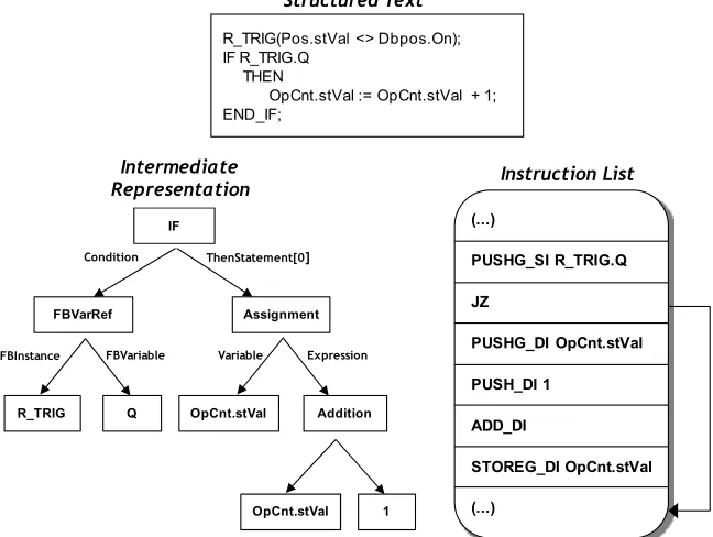
To exemplify the compiling process presented in this paper, fig. 10 contains an example of a program that counts the number of times that a circuit breaker opened. The open operation is detected by invoquing a standard function block, the rising edge detector. Fig. 10 shows the intermediate representation and the list of instructions generated for the if statement.
Structured Text Instruction List (...) PUSHG_SI R_TRIG.Q PUSHG_DI OpCnt.stVal JZ PUSH_DI 1 STOREG_DI OpCnt.stVal ADD_DI (...) Condition FBVarRef R_TRIG Q FBInstance FBVariable ThenStatement[0] Assignment OpCnt.stVal Variable Expression Addition 1 OpCnt.stVal IF Intermediate Representation
R_TRIG(Pos.stVal <> Dbpos.On); IF R_TRIG.Q
THEN
OpCnt.stVal := OpCnt.stVal + 1; END_IF;
Fig. 10. Example of compiling process outputs.
6. Compiler
Implementation
To assist the implementation of the ST Parser (Lexical Analyzer and
Syntactical Analyzer) we used ANTLR [4]. ANTLR, ANother Tool for
Language Recognition, is a language tool that provides a framework for constructing recognizers, compilers and translators from grammatical descriptions containing actions in a variety of target languages. To preserve the technology adopted by the INTEGRA project, the selected language was the C# [5].
Since the IEC 61131-3 [2] defines a context-free grammar for the ST language, to build the ST Parser it was necessary to adapt the standard grammar to fit the ANTLR syntax.
The meta-model of the Structured Text language described in the ASML was developed in a Meta-Modeling Framework from EFACEC, the Developer´s Workbench Modeler. This Meta-Modeling Framework was developed in order to enhance software development productivity. Through this framework meta-models may be defined, validated and C# code may be generated according to some generation rules. The ST Parser instantiates the
intermediate representation of each POU body according to the ST
meta-model defined in the ASML.
Through the Developer´s Workbench Modeler it is also possible to specify a set of model validation rules and generate a semantic validator. The
semantic analyzer was implemented using this approach.
The back-end of the compiler, the ObjectCode Generator, the Linker and
the Assembler were implemented in C#.
7. Results
and
Conclusions
In this paper we discussed a compiler architecture that supports multiple input languages and multiple target platforms. The integration of the textual language ST, described in the IEC 61131-3, in a model based engineering environment for control systems was presented and the ST Compiler as an application case study for the desired compiler architecture was described.
To simplify the generation of a target specific executable code the compiling process was organized in two stages: the compiling stage and the linking stage. The compiling stage adopts semantic-directed translation methodology and generates target and language independent code that can be used to generate any target/platform specific code. The linking/assembly stage generates executable code according to the target device configuration and platform definitions, being therefore independent of the source languages used.
It is also important to emphasize that the presented compiler architecture simplifies reuse, provides behavior encapsulation and makes use of library inclusion in the engineering environment.
The implementation illustrated in this paper was applied in an on-site control system pilot project effectively meeting the requirements of the INTEGRA project. Results of the project have also met sufficient quality criteria and are expected to be revised and incorporated in standard industrial products.
8. References
1. IEC 61131-1 Programmable controllers Part 1: General Information. (2003)
3. IEC 61131-8 Programmable controllers Part 8: Guidelines for the application and implementation of programming languages. (2003).
4. Parr, T: The Definitive ANTLR Reference: Building Domain-Specific Languages, First Edition. Pragmatic Bookshelf. (May 2007).
5. Jesse Liberty, Programming C#. Valerie Quercia, (2003).
6. Aho, Alfred V. and Lam, Monica S. and Sethi, Ravi and Ullman, Jeffrey D.: Compilers: Principles, Techniques, and Tools (2nd Edition). Addison Wesley (August 2006).
7. Waite, W., Goos, G.: Compiler Construction. Springer Verlag (1984). 8. Carrapatoso, A., Cartaxo, R., Matos, F., Paulo, R.:INTEGRA Project –
Applying IEC 61850 Technology. CIGRE (2006).
9. Paulo, R., Carvalho, A.: Towards Model-Driven Design of Substation Automation Systems.CIRED (2005).
10. OMG Unified Modeling Language, Infrastructure, V2.1.2. (November 2007).
11. Jouault, F., Bézivin, J.: KM3: a DSL for Metamodel Specification.
12. The Eclipse Modeling Framework (EMF) Overview, Available: http://help.eclipse.org/help33/index.jsp?topic=/org.eclipse.emf.doc//refere nces/overview/EMF.html.
13. Rzonca, D., Sadolewsky, J., Trybus, B.: Executable form of the IEC 61131-3 ST language programs in the CPDev environment. (2007).
Elisabete Fonseca Ferreira got a degree in "Mathematics and Computer
Science", at University of Minho, Portugal.
Currently holds a position as an R&D Engineer at Power Systems Automation Business Unit, EFACEC Group.
She has been involved in compiler and virtual machine development for embedded real-time devices. She is currently involved in the development of engineering tools.
Rogério Dias Paulo got a degree in “Industrial Electronics Engineering”, at
University of Minho, Portugal and MsC. in “Industrial Informatics” from the Oporto University, Portugal.
Currently holds an R&D Product Manager position at Power Systems Automation Business Unit, EFACEC Group.
Has been involved in several R&D or product development projects in the domains of Software engineering, Specification and development of communication stacks, Intelligent electronic devices and Engineering tools.
Daniela Carneiro da Cruz got a degree in "Mathematics and Computer
Science", at University of Minho), and now she is starting a Ph.D. degree in "Computer Science" also at University of Minho, under the MAPi doctoral program.
the area of Compilers and Formal Development of Language Processors; and Programming Languages and Paradigms (Procedural, Logic, and OO).
As a researcher of gEPL, Daniela is working with the development of compilers based on attribute grammars and automatic generation tools. She developed a completed compiler and a virtual machine for the LISS language (an imperative and powerful programming language conceived at UM). She was also involved in the PCVIA (Program Comprehension by Visual Inspection and Animation), a FCT funded national research project; in that context, Daniela worked in the implementation of "Alma", a program visualizer and animator tool for program understanding.
She is now enrolled in a new bilateral cooperation project with Slovenia under the subject "Program Comprehension for Domain Specific Languages".
Pedro Rangel Henriques got a degree in "Electrotechnical/Electronics
Engineering", at FEUP (Oporto University), and finished a Ph.D. thesis in "Formal Languages and Attribute Grammars" at University of Minho. In 1981 he joined the Computer Science Department of University of Minho, where he is a teacher/researcher.
Since 1995 he is the coordinator of the "Language Processing group". He teaches many different courses under the broader area of programming: Programming Languages and Paradigms (Procedural, Logic, Functional and OO); Compilers and Formal Development of Language Processors; etc. He is co-author of the "XML & XSL: da teoria a prática" book, publish by FCA in 2002.
Pedro Rangel Henriques has supervised M.Sc. (16) and Ph.D. (14) thesis, and more than 100 graduating trainingships/projects, in the areas of: language processing (textual and visual), and structured document processing; program animation and program comprehension; knowledge discovery from databases, data-mining, and data-cleaning.
He also was responsible for several applicational projects (in the interface University/external-community, industry), mainly in the area of information systems (databases and web oriented). From 2002 until 2004 he was the Head of the Department, and at moment he is the President of APPIA, the Portuguese Association for Artificial Intelligence.