aerospace
Article
SPH-FEM Design of Laminated Plies under
Bird-Strike Impact
Yadong Zhou1,* , Youchao Sun1,* and Tianlin Huang2
1 College of Civil Aviation, Nanjing University of Aeronautics and Astronautics, Nanjing 211100, China 2 Commercial Aircraft Engine Co., LTD, Aero Engine Cooperation of China, Shanghai 201100, China
* Correspondence: yzhou@nuaa.edu.cn (Y.Z.); sunyc@nuaa.edu.cn (Y.S.)
Received: 10 September 2019; Accepted: 3 October 2019; Published: 7 October 2019
Abstract: Composite laminates can potentially reduce the weight of aircrafts; however, they are
subjected to bird strike hazards in civil aviation. To handle their nonlinear dynamic behaviour, in this study, the impact damage of composite laminates were numerically evaluated and designed by means of smoothed particle hydrodynamics (SPH) and the finite element method (FEM) to simulate the interaction between bird projectiles and the laminates. Attention was mainly focused on the different damage modes in various laminates’ plies induced by bird impact on a square laminated plate. A continuum damage mechanics approach was exploited to simulate damage initiation and evolution in composite laminates. Damage maps were computed with respect to different ply angles, i.e., 0◦, 45◦and−45◦. The damage distributions were comparatively investigated, and then the
ply design was considered for crashworthiness improvement. The results aim to serve as a design guideline for future prototype-scale bird strike studies of complex laminated structures.
Keywords: bird strike; composite laminates; ply angles; impact damage; SPH-FEM
1. Introduction
As an important soft-body impact, structural damage induced by bird strike has become an increasingly serious and catastrophic issue in the civil aviation industry [1,2], particularly threatening the safety of aircraft and passengers, e.g., loss of aircrafts and even the loss of lives. Therefore, there is a great need to improve the bird strike resistance of aircraft structures by developing high-performance materials and better crashworthiness designs [3]. Generally, bird strike is a short duration (generally in the millisecond range) and high-intensity loading event, with complex coupling interactions. Under the bird soft-body impacts, some critical parameters, e.g., geometry effects of birds [4–7], material’s models of birds [8–10], initial velocities and impact angles of the bird projectile [10–13], etc., can influence the deformations and damage mechanisms of the front-facing structures.
Due to their fine mechanical properties, composite laminates are now used as key materials for aircraft’s front-facing components, e.g., the fan blades of aeroengine structures. Composite laminates offer the potential for reducing the weight of civil aircrafts, and hence some civil aircraft models in China, e.g., C919, are seeking to use composite laminates in key components in the future. Meanwhile, bird strike certification compliance, e.g., FAR Part 25, should be considered [14,15]. For these applications, composite laminates undergo complex internal damage when they are subjected to foreign object damage (FOD) via impacts. In terms of composite materials under impact loadings, the laminated layup will be critically vital [16–18]. With much more complexity compared to metal materials, several failure modes in composite materials can be caused by impact loading, such as fiber fracture, matrix cracking, delamination, etc. For the damage and failure modes of composite materials upon FOD, influential factors mainly include structural geometries [15,19], impact velocity/locations [20–22], properties of the projectile [20], layer configurations [17,19,23,24], fiber and matrix properties [25], etc.
Aerospace2019,6, 112 2 of 14
Complex composite structures under impact-induced FOD has been an important issue, and hence, bird strike damage and crashworthiness have gained much attention in recent years. Guida et al. [3] assessed the bird strike resistance improvement of a laminated leading edge, where different layups A/0/90/A/90/0/A and A/0/90/A were considered, where A refers to a 0.3 mm layer of aluminium alloy. Heimbs et al. [26] investigated the bird strike behaviour of pre-stressed composite plates, in which various cohesive interfaces were modelled. Grimaldi et al. [19] studied square composite plates with multiple layups, and evaluated the capability of windshields to absorb the impact energy during a bird strike. Farooq et al. [27] predicted the impact threshold loads of composite panels with different numbers of plies. Ali et al. [28] reviewed the palliatives for low-velocity impact damage in composite laminates, such as short fibre reinforcement and particle-based interlayers. Minak et al. [29] and Saghafi et al. [30] respectively investigated the pre-stress effect on impact responses of curved laminates, in the front- and back-surface plies. Hedayati et al. [17,31] conducted a bird strike analysis with different layup materials and different positions of the reinforced ply. Recently, Mohagheghian et al. [16] found that the polymer interlayer type had the most significant effect on both deformations and failure modes of the laminated glass windows at room temperature. Riccio et al. [32] analysed the state-of-the-art formulations for the bird and composite wing modelling in detail, providing discussion on the added value and the weak points. Orlando et al. [33] studied a composite flap configuration compliant with EASA and FAA bird strike requirements. Di Caprio et al. [34] considered the unidirectional fiber-reinforced composite material systems of wing leading edges, for the outer and inner faces of the skins under a bird impact event, with various skin thicknesses considered. According to the airworthiness requirements, Guida et al. [35] adapted an innovative layup on an aeronautical structure, which was subjected to the bird strike phenomenon at 180 m/s and with an impacting mass of 1.8 kg. The authors [36] have recently studied the bird strike damage modes in rotational composite laminates, with the ply angles fixed. Dealing with extreme loadings, analysis and design of sandwich panels under both air-blast loading [37] and low-velocity impact [38] have been recently considered.
As it can be seen from the many previous studies, bird strike analysis of composite materials and structures has drawn more and more attention recently; but many aspects still need to be solved for real applications to key aeronautical components. The total thickness of composite laminates in aerospace structures is a limit [17]; therefore, it is highly valuable to fully exploit their designability under complex loadings. The ply angles of the laminated structures under a bird impact were considered inadequately, which should be taken into account for further applications. In the primary design phase, full-scale experiments with trial and error are very expensive and time-consuming due to the complexity of bird strikes on composites. For these considerations, the main objective of the present work is to numerically investigate the ply angle’s effect on the impact-induced damage of laminated plates, which should tentatively give general design guidelines for future prototype-scale experimental studies of laminated structures in real aeronautical systems with more complexity.
2. SPH-FEM Computational Model
The bird’s mechanical property actually changes from the low-velocity to the high-velocity regimes [4]. To simulate the bird’s behaviours, there are three most-suggested methods [39], namely Lagrangian, arbitrary Lagrangian Eulerian (ALE) and smoothed particle hydrodynamics (SPH). Among these methods, SPH can better describe bird fragmentation into discrete particles with high efficiency. Therefore, SPH has recently experienced high popularity [2,5,10,15,16,32,33,40,41] in bird strike, high-velocity impact, and other large deformation studies. In the present study, a SPH method was employed, represented by a set of discrete but interacting particles, which belong to a meshless particle-based method.
Aerospace2019,6, 112 3 of 14
for the analytical relation equation aspv=RT. Letρbe the current mass density; in order to model the hydrodynamic response of fluidic bird’s material accurately, an EOS needs to be employed as
p= f(ρ,Em) (1)
whereEmis the internal energy per unit mass. Common forms of EOS that are extensively adopted
include polynomial, Mie-Grüneisen and Murnaghan forms [2]. In this article, in order to predict the behaviour of birds well, a Mie-Grüneisen EOS is adopted as
p−pH=Γρ(Em−EH) (2)
wherepHandEHrepresent the Hugoniot pressure and specific energy (per unit mass), respectively.
The Hugoniot pressure is referred to as the initial pressure peak in the contact point in a perpendicular impact, and is mathematically defined aspH=ρ0U0Us. It can be seen that the Hugoniot pressure is a
function of the initial density of the impactor (ρ0), the initial velocity of the impactor (U0), and the shock wave velocity (Us).Γis the Grüneisen ratio defined as
Γ=Γ0ρ0
ρ (3)
whereΓ0represents a material constant,ρ0represents the reference density andρis the current density. The Hugoniot energy (EH) can be related to the Hugoniot pressure (pH) by
EH=
pHη
2ρ0 (4)
whereη=1−ρ0/ρ. From the above equations, we can yield
p=pH 1−
Γ0η 2
!
+Γ0ρ0Em (5)
The linear Mie-Grüneisen EOS (called aUs−UpEOS) was employed to describe a linear relationship
between the shock and particle velocities. A typicalUs−UpEOS can be given as
pH=
ρ0c20η
(1−sη)2 (6)
The linear relationship between the linear shock velocityUsand the particle velocityUpcan be
defined byc0ands, asUs=c0+sUp. Under the above assumptions, the linearUs−UpHugoniot form
can be deduced as
p= ρ0c 2 0η
(1−sη)2 1
−Γ0η
2 !
+Γ0ρ0Em (7)
In the present simulation, SPH modelling was conducted in ABAQUS/Explicit by using PC3D element. The EOS parametersc0,sandΓ0are material constants with values ofc0=1483 m/s,s=0 and
Γ0=0. Different substitute bird impactor geometries were proposed, e.g., the cylinder, the cylinder with hemispherical ends, the ellipsoid and the sphere [39], but there is no standardized artificial bird shape. The bird body here is modelled as a cylinder (aspect ratio=2:1) projectile, with 200 mm length and 100 mm diameter. The bird strike velocity was fixed at 60 m/s. The projectile has an initial density ofρ0=950 kg/m3, and the weight of the projectile model is≈1.5 kg. A total of 473 particles were used
to model the bird projectile, and the distances between the particles were approximately 10 mm. For calibration of the material constants, an experiment was conducted on a 600 mm×600 mm×2 mm steel plate under a 84.2 m/s bird strike [15]. For convenience in studying
Aerospace2019,6, 112 4 of 14
can be efficiently modelled by means of the finite element method (FEM) [19,32,42]. For the fiber breakage and matrix cracking simulation, continuum damage mechanics (CDM) enables one to predict with fine accuracy the onset and growth of damages, by introducing degradation factors for the material propertiesdf,dmanddsfor fiber, matrix and shear modes, respectively. The damaged elasticity
matrixCdhas the following form
Cd= 1
D
1−dfE11 1−df(1−dm)ν21E11 0
1−df(1−dm)ν12E22 (1−dm)E22 0
0 0 (1−ds)G12D
(8)
whereD=1−(1−df)(1−dm)ν12ν21. The degradation factors range from 0 to 1, corresponding to the
intact and fully-damaged states, respectively. In the present simulations, the laminate edge length and projectile length are 500 mm and 200 mm, respectively. The initial impact radius is 50 mm and the initial distance between the projectile and the target is 100 mm, which defines the initial position of the projectile’s centre of mass. The thickness of the composite laminated plate is 1.2 mm, with an initial laminate layup [0/45/0/−45]s. Namely, eight-ply laminate was considered, which is similar to [27].
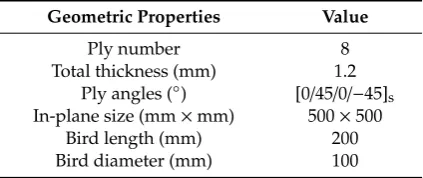
The geometric details of the plate and the bird are as shown in Table1.
Table 1.The geometric dimensions of the initially-considered plies and the bird projectile.
Geometric Properties Value
Ply number 8
Total thickness (mm) 1.2
Ply angles (◦) [0/45/0/−45]s
In-plane size (mm×mm) 500×500
Bird length (mm) 200
Bird diameter (mm) 100
The plate was clamped, supported on the four edges. By increasing the mesh density until the mesh showed no significant change in results, the refined mesh density was determined by performing repeated analyses; in particular, it was found that the projectile meshes should be symmetrical. The final numerical model of the impacted plate consists of 2500 conventional shell finite elements (linear quadrilateral elements S4R in ABAQUS). Hashin’s criteria formulation [43] was adopted for evaluating the failure modes, which can enable the prediction of fiber and matrix failure onsets in compression or tension for each mode.
The orthotropic elasticity, mass density and strength parameters of a unidirectional CFRP material are listed in Table2for the present simulations. In the table,E11represents the Young’s modulus in the fiber direction;E22 represents the Young’s modulus in the direction perpendicular to the fibers; G12 represents the shear modulus;ν12 represents Poisson’s ratios; XT represents the longitudinal tensile strength;XCrepresents the longitudinal compressive strength;YTrepresents the transverse tensile strength;YCrepresents the transverse compressive strength; andS12,S
13andS23represent the shear strength.
Aerospace2019,6, 112 5 of 14
Table 2.Mechanical properties of the CFRP lamina [45].
Property Type Notation Value
Mass density ρ(kg/m3) 1600
Orthotropic elasticity
E11(GPa) 181
E22(GPa) 10.3
G12(GPa) 7.17
G13(GPa) 1.0
G23(GPa) 0.5
ν12 0.28
Strength
XT=XC(MPa) 1500
YT(MPa) 40
YC(MPa) 246
S12(MPa) 200
S13=S23(MPa) 123
Table 3.In-plane fracture properties of the composite lamina.
Notation Value
GT
1C 11.5 kJ/m2
GC1C 4.1 kJ/m2
GT2C 0.35 kJ/m2
GC2C 3.2 kJ/m2
Aerospace 2019, 6, x 5 of 14
Table 2. Mechanical properties of the CFRP lamina [45].
Property type Notation Value
Mass density ρ (kg/m3) 1600
Orthotropic elasticity
E11 (GPa) 181 E22 (GPa) 10.3 G12 (GPa) 7.17 G13 (GPa) 1.0 G23 (GPa) 0.5
ν12 0.28
Strength
XT = XC (MPa) 1500 YT (MPa) 40 YC (MPa) 246 S12 (MPa) 200 S13 = S23 (MPa) 123
Table 3. In-plane fracture properties of the composite lamina.
Notation Value
1
T C
G
11.5 kJ/m21
C C
G
4.1 kJ/m22
T C
G
0.35 kJ/m22
C C
G
3.2 kJ/m2Figure 1. Cylinder artificial bird projectile made of gelatin jelly in bird strike experiments.
Figure 2. SPH-FEM model of composite laminates under bird impact.
X Y
Z
t = 0.15 t = 0.15 t = 0.15
Ply−1−Copy1 Ply−2−Copy1 Ply−3−Copy1 Ply−4−Copy1 Ply−4 Ply−3 Ply−2 Ply−1 1 2 3 Layup: "CompositeLayup−1" Total thickness: 1.200000. Plot of plies 1 to 8, of 8.
Projectile SPH: PC3D
Laminate FEM: S4R
Figure 1.Cylinder artificial bird projectile made of gelatin jelly in bird strike experiments.
Aerospace 2019, 6, x 5 of 14
Table 2. Mechanical properties of the CFRP lamina [45].
Property type Notation Value
Mass density ρ (kg/m3) 1600
Orthotropic elasticity
E11 (GPa) 181 E22 (GPa) 10.3 G12 (GPa) 7.17 G13 (GPa) 1.0 G23 (GPa) 0.5
ν12 0.28
Strength
XT = XC (MPa) 1500 YT (MPa) 40 YC (MPa) 246 S12 (MPa) 200 S13 = S23 (MPa) 123
Table 3. In-plane fracture properties of the composite lamina.
Notation Value
1
T C
G
11.5 kJ/m21
C C
G
4.1 kJ/m22
T C
G
0.35 kJ/m22
C C
G
3.2 kJ/m2Figure 1. Cylinder artificial bird projectile made of gelatin jelly in bird strike experiments.
Figure 2. SPH-FEM model of composite laminates under bird impact.
X Y
Z
t = 0.15 t = 0.15 t = 0.15
Ply−1−Copy1 Ply−2−Copy1 Ply−3−Copy1 Ply−4−Copy1 Ply−4 Ply−3 Ply−2 Ply−1 1 2 3 Layup: "CompositeLayup−1" Total thickness: 1.200000. Plot of plies 1 to 8, of 8.
Projectile SPH: PC3D
Laminate FEM: S4R
Aerospace2019,6, 112 6 of 14
Aerospace 2019, 6, x 6 of 14
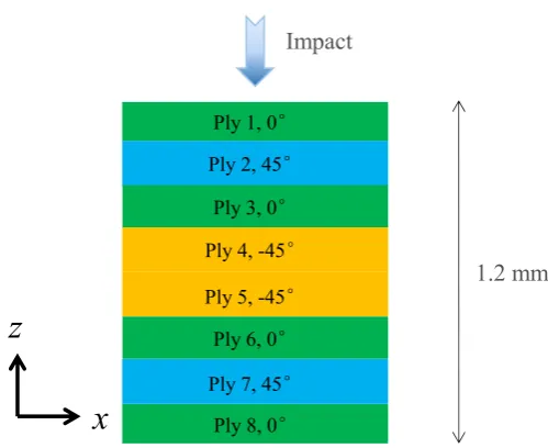
Figure 3. Ply angles of the initial composite laminate.
3. Results and Discussion
For such analysis of an extremely discontinuous processes, an explicit dynamic analysis was carried out using ABAQUS/Explicit, which is considered to be computationally efficient for the analysis of large models with relatively short dynamic response times. The projectile begins to initially contact the impacted plate at approximately 1.7 ms, and the total simulation duration was 10 ms.
Bird impacts with high kinetic energy, can produce severe laminar damage, e.g., fiber fracture and matrix cracking. In the failure modes of composite laminates, the fiber fracture can result in catastrophic failure of overall laminated structures; therefore, in this section, attention will be firstly focused on the fiber-tension failure mode if not specified. Then, some other critical failure modes will be also evaluated.
Figure 4. Damage maps of the first two plies (front side): (a) the ply 1, 0°, (b) the ply 2, 45°.
Figure 4 illustrates the damage maps of the fiber tension of the first two plies: (a) the first ply at the impacted side; (b) the second ply at the impacted side. The center of the rectangular laminate is (0,0,0), and the center of the initial impact area is also (0,0,0) as the white dots (projectile particles)
Ply 3, 0°
Ply 1, 0°
Ply 2, 45°
Ply 4, -45°
Ply 5, -45°
Ply 6, 0°
Ply 7, 45°
Ply 8, 0°
z
x
Impact
1.2 mm
0.000 0.046 0.092 0.138 0.184 0.230 0.276 0.322 0.368 0.414 0.460 0.506 0.552
Step: Step−1
Increment 9450: Step Time = 1.0000E−02 Primary Var: DAMAGEFT
Deformed Var: not set Deformation Scale Factor: not set Status Var: STATUS
X Y
Z
0.000 0.046 0.091 0.137 0.182 0.228 0.273 0.319 0.364 0.410 0.455 0.501 0.546
Step: Step−1
Increment 9450: Step Time = 1.0000E−02 Primary Var: DAMAGEFT
Deformed Var: not set Deformation Scale Factor: not set Status Var: STATUS
X Y
Z
(a)
(b)
Figure 3.Ply angles of the initial composite laminate.
3. Results and Discussion
For such analysis of an extremely discontinuous processes, an explicit dynamic analysis was carried out using ABAQUS/Explicit, which is considered to be computationally efficient for the analysis of large models with relatively short dynamic response times. The projectile begins to initially contact the impacted plate at approximately 1.7 ms, and the total simulation duration was 10 ms.
Bird impacts with high kinetic energy, can produce severe laminar damage, e.g., fiber fracture and matrix cracking. In the failure modes of composite laminates, the fiber fracture can result in catastrophic failure of overall laminated structures; therefore, in this section, attention will be firstly focused on the fiber-tension failure mode if not specified. Then, some other critical failure modes will be also evaluated.
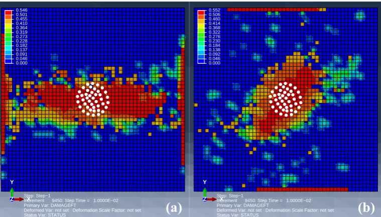
Figure4illustrates the damage maps of the fiber tension of the first two plies: (a) the first ply at the impacted side; (b) the second ply at the impacted side. The center of the rectangular laminate is (0,0,0), and the center of the initial impact area is also (0,0,0) as the white dots (projectile particles) indicate in Figure4. It can be observed that the initial impact location is the highly damaged area, while the damage propagations are along different directions in Figure4a,b. Furthermore, the damage at the boundaries are very different. Damage also propagates along the boundary, and the severity is also rather high due to high tension stress in the clamped boundary. Results show that damage initiates and mainly propagates along the fiber direction of the ply. In 0◦-fiber ply, the damage is almost widely distributed from the impacted area to the boundary; however, for 45◦-fiber ply, intermittent regions appear in the damage from the impacted area to the boundary. This phenomenon indicates that bird impact damage may be locally distributed for such clamped 45◦ply.
Aerospace2019,6, 112 7 of 14
Aerospace 2019, 6, x 6 of 14
Figure 3. Ply angles of the initial composite laminate.
3. Results and Discussion
For such analysis of an extremely discontinuous processes, an explicit dynamic analysis was carried out using ABAQUS/Explicit, which is considered to be computationally efficient for the analysis of large models with relatively short dynamic response times. The projectile begins to initially contact the impacted plate at approximately 1.7 ms, and the total simulation duration was 10 ms.
Bird impacts with high kinetic energy, can produce severe laminar damage, e.g., fiber fracture and matrix cracking. In the failure modes of composite laminates, the fiber fracture can result in catastrophic failure of overall laminated structures; therefore, in this section, attention will be firstly focused on the fiber-tension failure mode if not specified. Then, some other critical failure modes will be also evaluated.
Figure 4. Damage maps of the first two plies (front side): (a) the ply 1, 0°, (b) the ply 2, 45°.
Figure 4 illustrates the damage maps of the fiber tension of the first two plies: (a) the first ply at the impacted side; (b) the second ply at the impacted side. The center of the rectangular laminate is (0,0,0), and the center of the initial impact area is also (0,0,0) as the white dots (projectile particles)
Ply 3, 0°
Ply 1, 0°
Ply 2, 45°
Ply 4, -45°
Ply 5, -45°
Ply 6, 0°
Ply 7, 45°
Ply 8, 0°
z
x
Impact
1.2 mm
0.000 0.046 0.092 0.138 0.184 0.230 0.276 0.322 0.368 0.414 0.460 0.506 0.552 Step: Step−1Increment 9450: Step Time = 1.0000E−02 Primary Var: DAMAGEFT
Deformed Var: not set Deformation Scale Factor: not set Status Var: STATUS
X Y Z 0.000 0.046 0.091 0.137 0.182 0.228 0.273 0.319 0.364 0.410 0.455 0.501 0.546 Step: Step−1
Increment 9450: Step Time = 1.0000E−02 Primary Var: DAMAGEFT
Deformed Var: not set Deformation Scale Factor: not set Status Var: STATUS
X Y
Z
(a)
(b)
Figure 4.Damage maps of the first two plies (front side): (a) the ply 1, 0◦, (b) the ply 2, 45◦.
Aerospace 2019, 6, x 7 of 14
indicate in Figure 4. It can be observed that the initial impact location is the highly damaged area, while the damage propagations are along different directions in Figure 4a,b. Furthermore, the damage at the boundaries are very different. Damage also propagates along the boundary, and the severity is also rather high due to high tension stress in the clamped boundary. Results show that damage initiates and mainly propagates along the fiber direction of the ply. In 0°-fiber ply, the damage is almost widely distributed from the impacted area to the boundary; however, for 45°-fiber ply, intermittent regions appear in the damage from the impacted area to the boundary. This phenomenon indicates that bird impact damage may be locally distributed for such clamped 45° ply.
Figure 5. Damage maps of the rear first two plies: (a) 8th (0° ply) and (b) 7th (45° ply).
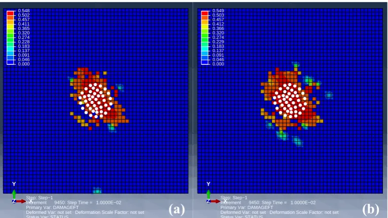
Figure 5 shows the ultimate damage maps (damage at 10 ms) of the first two plies in the rear side: (a) the first ply at the rear side; (b) the second ply at the rear side. The damaged regions have an approximately similar area, but along different directions because of the different fiber directions. The local contact regions are the highest damaged, while the damage along the boundaries are less distributed for both cases. This is because the boundary of the rear side experiences compressive deformations. 0.000 0.046 0.093 0.139 0.186 0.232 0.279 0.325 0.372 0.418 0.465 0.511 0.558 Step: Step−1
Increment 9450: Step Time = 1.0000E−02 Primary Var: DAMAGEFT
Deformed Var: not set Deformation Scale Factor: not set Status Var: STATUS
X Y Z 0.000 0.047 0.094 0.141 0.187 0.234 0.281 0.328 0.375 0.422 0.469 0.515 0.562 Step: Step−1
Increment 9450: Step Time = 1.0000E−02 Primary Var: DAMAGEFT
Deformed Var: not set Deformation Scale Factor: not set Status Var: STATUS
X Y Z
(a)
(b)
0.000 0.046 0.091 0.137 0.183 0.228 0.274 0.320 0.365 0.411 0.457 0.502 0.548 Step: Step−1Increment 9450: Step Time = 1.0000E−02 Primary Var: DAMAGEFT
Deformed Var: not set Deformation Scale Factor: not set Status Var: STATUS
X Y Z 0.000 0.046 0.091 0.137 0.183 0.229 0.274 0.320 0.366 0.412 0.457 0.503 0.549 Step: Step−1
Increment 9450: Step Time = 1.0000E−02 Primary Var: DAMAGEFT
Deformed Var: not set Deformation Scale Factor: not set Status Var: STATUS
X Y
Z
(a)
(b)
Figure 5.Damage maps of the rear first two plies: (a) 8th (0◦ply) and (b) 7th (45◦ply).
Figure6compares the damage maps of the middle two−45◦
plies (the ply 4 and 5). The impacted area experienced local damage along the−45◦direction, while the non-contacted zones had almost
zero damage. The reasons can be divided into two portions. First, the middle layers have a smaller stress response than the front or rear layers do. Second,−45◦ plies have a longer distance to the
clamped boundary, i.e., larger area to bear the impact loading. According to this damage mechanism of the laminate, it can be expected that±45◦plies will give more locally-distributed impact damage.
Aerospace2019,6, 112 8 of 14
Aerospace 2019, 6, x 7 of 14
indicate in Figure 4. It can be observed that the initial impact location is the highly damaged area, while the damage propagations are along different directions in Figure 4a,b. Furthermore, the damage at the boundaries are very different. Damage also propagates along the boundary, and the severity is also rather high due to high tension stress in the clamped boundary. Results show that damage initiates and mainly propagates along the fiber direction of the ply. In 0°-fiber ply, the damage is almost widely distributed from the impacted area to the boundary; however, for 45°-fiber ply, intermittent regions appear in the damage from the impacted area to the boundary. This phenomenon indicates that bird impact damage may be locally distributed for such clamped 45° ply.
Figure 5. Damage maps of the rear first two plies: (a) 8th (0° ply) and (b) 7th (45° ply).
Figure 5 shows the ultimate damage maps (damage at 10 ms) of the first two plies in the rear side: (a) the first ply at the rear side; (b) the second ply at the rear side. The damaged regions have an approximately similar area, but along different directions because of the different fiber directions. The local contact regions are the highest damaged, while the damage along the boundaries are less distributed for both cases. This is because the boundary of the rear side experiences compressive deformations. 0.000 0.046 0.093 0.139 0.186 0.232 0.279 0.325 0.372 0.418 0.465 0.511 0.558 Step: Step−1
Increment 9450: Step Time = 1.0000E−02 Primary Var: DAMAGEFT
Deformed Var: not set Deformation Scale Factor: not set Status Var: STATUS
X Y Z 0.000 0.047 0.094 0.141 0.187 0.234 0.281 0.328 0.375 0.422 0.469 0.515 0.562 Step: Step−1
Increment 9450: Step Time = 1.0000E−02 Primary Var: DAMAGEFT
Deformed Var: not set Deformation Scale Factor: not set Status Var: STATUS
X Y Z
(a)
(b)
0.000 0.046 0.091 0.137 0.183 0.228 0.274 0.320 0.365 0.411 0.457 0.502 0.548 Step: Step−1Increment 9450: Step Time = 1.0000E−02 Primary Var: DAMAGEFT
Deformed Var: not set Deformation Scale Factor: not set Status Var: STATUS
X Y Z 0.000 0.046 0.091 0.137 0.183 0.229 0.274 0.320 0.366 0.412 0.457 0.503 0.549 Step: Step−1
Increment 9450: Step Time = 1.0000E−02 Primary Var: DAMAGEFT
Deformed Var: not set Deformation Scale Factor: not set Status Var: STATUS
X Y
Z
(a)
(b)
Figure 6.Damage maps of the middle two−45◦
plies: (a) 4th and (b) 5th.
Aerospace 2019, 6, x 8 of 14
Figure 6. Damage maps of the middle two −45° plies: (a) 4th and (b) 5th.
Figure 6 compares the damage maps of the middle two −45° plies (the ply 4 and 5). The impacted area experienced local damage along the −45° direction, while the non-contacted zones had almost zero damage. The reasons can be divided into two portions. First, the middle layers have a smaller stress response than the front or rear layers do. Second, −45° plies have a longer distance to the clamped boundary, i.e., larger area to bear the impact loading. According to this damage mechanism of the laminate, it can be expected that ±45° plies will give more locally-distributed impact damage. It can be observed from Figures 4–6 that correlation exists between the ply angles and damage modes. Considering these results, a designed plies can be proposed, as in Figure 7, to possibly achieve more locally-distributed impacted damage modes, by using ±45° plies.
Figure 7. Designed plies of the composite laminate with all ±45° plies.
Figure 8. The envelope fiber-tension damage maps of the initial (a) and designed (b) laminates.
The designed plies of the composite laminate consist of all ±45° plies. Figure 8 gives the damage maps in the all plies (i.e., the envelope damage of each ply), for both the initial and designed ply angles. The white dotted boxes in Figure 8a,b have the same shape and area, which is for comparative
Ply 1, 45°
Ply 2, -45°
Ply 3, 45°
Ply 4, -45°
Ply 5, -45°
Ply 6, 45°
Ply 7, -45°
Ply 8, 45°
Impact
z
x
1.2 mm
0.000 0.047 0.094 0.141 0.187 0.234 0.281 0.328 0.375 0.422 0.469 0.515 0.562 Step: Step−1Increment 9450: Step Time = 1.0000E−02 Primary Var: DAMAGEFT
Deformed Var: not set Deformation Scale Factor: not set Status Var: STATUS
X Y Z 0.000 0.047 0.094 0.141 0.188 0.234 0.281 0.328 0.375 0.422 0.469 0.516 0.563 Step: Step−1
Increment 7070: Step Time = 1.0000E−02 Primary Var: DAMAGEFT
Deformed Var: not set Deformation Scale Factor: not set Status Var: STATUS
X Y
Z
(a)
(b)
Figure 7.Designed plies of the composite laminate with all±45◦plies.
The designed plies of the composite laminate consist of all±45◦plies. Figure8gives the damage
Aerospace2019,6, 112 9 of 14
Aerospace 2019, 6, x 8 of 14
Figure 6. Damage maps of the middle two −45° plies: (a) 4th and (b) 5th.
Figure 6 compares the damage maps of the middle two −45° plies (the ply 4 and 5). The impacted area experienced local damage along the −45° direction, while the non-contacted zones had almost zero damage. The reasons can be divided into two portions. First, the middle layers have a smaller stress response than the front or rear layers do. Second, −45° plies have a longer distance to the clamped boundary, i.e., larger area to bear the impact loading. According to this damage mechanism of the laminate, it can be expected that ±45° plies will give more locally-distributed impact damage. It can be observed from Figures 4–6 that correlation exists between the ply angles and damage modes. Considering these results, a designed plies can be proposed, as in Figure 7, to possibly achieve more locally-distributed impacted damage modes, by using ±45° plies.
Figure 7. Designed plies of the composite laminate with all ±45° plies.
Figure 8. The envelope fiber-tension damage maps of the initial (a) and designed (b) laminates.
The designed plies of the composite laminate consist of all ±45° plies. Figure 8 gives the damage maps in the all plies (i.e., the envelope damage of each ply), for both the initial and designed ply angles. The white dotted boxes in Figure 8a,b have the same shape and area, which is for comparative
Ply 1, 45°
Ply 2, -45°
Ply 3, 45°
Ply 4, -45°
Ply 5, -45°
Ply 6, 45°
Ply 7, -45°
Ply 8, 45°
Impact
z
x
1.2 mm
0.000 0.047 0.094 0.141 0.187 0.234 0.281 0.328 0.375 0.422 0.469 0.515 0.562
Step: Step−1
Increment 9450: Step Time = 1.0000E−02 Primary Var: DAMAGEFT
Deformed Var: not set Deformation Scale Factor: not set Status Var: STATUS
X Y
Z
0.000 0.047 0.094 0.141 0.188 0.234 0.281 0.328 0.375 0.422 0.469 0.516 0.563
Step: Step−1
Increment 7070: Step Time = 1.0000E−02 Primary Var: DAMAGEFT
Deformed Var: not set Deformation Scale Factor: not set Status Var: STATUS
X Y
Z
(a)
(b)
Figure 8.The envelope fiber-tension damage maps of the initial (a) and designed (b) laminates.
Aerospace 2019, 6, x 9 of 14
purposes. The results indicate that bird-impact damage is globally-distributed for the initial laminate; but locally-distributed for the designed one. The highest-damaged regions also distribute along the clamped boundary in the initial plies. The results of these final damage maps indicate that the effect of ply angles can greatly influence the damage modes, which are mainly through the different damaged areas. Although energy that was slightly higher dissipated in the laminate with 0° plies (as shown in Figure 9), attention had to mainly focus on the damaged areas for the purpose of future real applications. Furthermore, it can be seen that the maximum damage index shows local characteristics, remaining almost identical (≈ 0.56).
0 2 4 6 8 10
0 5 10 15 20 25 30 35
Dam
age dissip
ation energ
y (J)
Time (ms)
Initial Designed
Figure 9. Damage dissipation energies in the initial and designed laminates.
Figure 10 describes the time histories of kinetic energies in the initial and designed models. In the impact process, the overall trends and curve shapes of the two kinetic energies show agreement. However, the kinetic energy curve of the designed case shows a right shift in the graph compared with the initial case. Such right shifting shows that the impact motion experienced a time lag in the designed case, which can be attributed to the changed laminated plies.
Figure 10. The time histories of kinetic energies in the initial and designed models. Figure 9.Damage dissipation energies in the initial and designed laminates.
Figure10describes the time histories of kinetic energies in the initial and designed models. In the impact process, the overall trends and curve shapes of the two kinetic energies show agreement. However, the kinetic energy curve of the designed case shows a right shift in the graph compared with the initial case. Such right shifting shows that the impact motion experienced a time lag in the designed case, which can be attributed to the changed laminated plies.
Aerospace2019,6, 112 10 of 14
Aerospace 2019, 6, x 9 of 14
purposes. The results indicate that bird-impact damage is globally-distributed for the initial laminate; but locally-distributed for the designed one. The highest-damaged regions also distribute along the clamped boundary in the initial plies. The results of these final damage maps indicate that the effect of ply angles can greatly influence the damage modes, which are mainly through the different damaged areas. Although energy that was slightly higher dissipated in the laminate with 0° plies (as shown in Figure 9), attention had to mainly focus on the damaged areas for the purpose of future real applications. Furthermore, it can be seen that the maximum damage index shows local characteristics, remaining almost identical (≈ 0.56).
0 2 4 6 8 10
0 5 10 15 20 25 30 35 Dam age dissip ation energ y (J) Time (ms) Initial Designed
Figure 9. Damage dissipation energies in the initial and designed laminates.
Figure 10 describes the time histories of kinetic energies in the initial and designed models. In the impact process, the overall trends and curve shapes of the two kinetic energies show agreement. However, the kinetic energy curve of the designed case shows a right shift in the graph compared with the initial case. Such right shifting shows that the impact motion experienced a time lag in the designed case, which can be attributed to the changed laminated plies.
Figure 10. The time histories of kinetic energies in the initial and designed models. Figure 10.The time histories of kinetic energies in the initial and designed models.
Aerospace 2019, 6, x 10 of 14
After comparing the fiber-tension damage mode, it is also worthwhile examining the other damage modes. It was observed that very small, similar damage appeared in the fiber-compression and matrix-compression modes of both the initial and designed laminates. Figure 11 compares the envelope matrix-tension damage maps of the initial (a) and designed (b) laminates. It is observed that both the initial and ±45° plies shared a similar damage map in this mode, with most of the regions damaged.
Figure 11. The envelope matrix-tension damage maps of the initial (a) and designed (b) laminates.
For the plate surface facing the bird projectile, the fiber-compression damage is also critical, due to the possibility of fiber buckling failure under compressive deformation. Figure 12 displays the fiber-compression damage of the foremost plies (i.e., the ply directly contacted by the bird projectile) in the two laminates: (a) initial; (b) designed. Local damage distributions in the vicinity of the initially contacted regions can be observed for both models.
Figure 12. The fiber compression damage of the foremost plies: (a) initial; (b) designed.
The impact deflection can be considered as an indicator of the structural stiffness. Figure 13 depicts the deflections of the plate’s centres in the two laminates. On the one hand, the peaks of the designed laminate were found to be a little larger than the initial one, which indicates that the ±45° designed plies slightly decrease the structural local stiffness to a small degree. On the other hand, the
(Avg: 75%) Envelope (max abs) DAMAGEMT +0.000e+00 +4.698e−02 +9.397e−02 +1.410e−01 +1.879e−01 +2.349e−01 +2.819e−01 +3.289e−01 +3.759e−01 +4.229e−01 +4.698e−01 +5.168e−01 +5.638e−01 X Y Z
(b)
(Avg: 75%) Envelope (max abs) DAMAGEMT +0.000e+00 +4.699e−02 +9.397e−02 +1.410e−01 +1.879e−01 +2.349e−01 +2.819e−01 +3.289e−01 +3.759e−01 +4.229e−01 +4.699e−01 +5.168e−01 +5.638e−01 X Y Z(a)
(Avg: 75%) PLY−1−COPY1 (top) DAMAGEFC +0.000e+00 +4.688e−02 +9.376e−02 +1.406e−01 +1.875e−01 +2.344e−01 +2.813e−01 +3.282e−01 +3.750e−01 +4.219e−01 +4.688e−01 +5.157e−01 +5.625e−01 Step: Step−1Increment 10109: Step Time = 1.0000E−02 Primary Var: DAMAGEFC
X Y Z
(a)
(Avg: 75%) PLY−1−COPY1 (top) DAMAGEFC +0.000e+00 +4.696e−02 +9.391e−02 +1.409e−01 +1.878e−01 +2.348e−01 +2.817e−01 +3.287e−01 +3.757e−01 +4.226e−01 +4.696e−01 +5.165e−01 +5.635e−01 Step: Step−1Increment 7499: Step Time = 1.0000E−02 Primary Var: DAMAGEFC
X Y
Z
(b)
Figure 11.The envelope matrix-tension damage maps of the initial (a) and designed (b) laminates.
For the plate surface facing the bird projectile, the fiber-compression damage is also critical, due to the possibility of fiber buckling failure under compressive deformation. Figure12displays the fiber-compression damage of the foremost plies (i.e., the ply directly contacted by the bird projectile) in the two laminates: (a) initial; (b) designed. Local damage distributions in the vicinity of the initially contacted regions can be observed for both models.
The impact deflection can be considered as an indicator of the structural stiffness. Figure13depicts the deflections of the plate’s centres in the two laminates. On the one hand, the peaks of the designed laminate were found to be a little larger than the initial one, which indicates that the±45◦designed
Aerospace2019,6, 112 11 of 14
Aerospace 2019, 6, x 10 of 14
After comparing the fiber-tension damage mode, it is also worthwhile examining the other damage modes. It was observed that very small, similar damage appeared in the fiber-compression and matrix-compression modes of both the initial and designed laminates. Figure 11 compares the envelope matrix-tension damage maps of the initial (a) and designed (b) laminates. It is observed that both the initial and ±45° plies shared a similar damage map in this mode, with most of the regions damaged.
Figure 11. The envelope matrix-tension damage maps of the initial (a) and designed (b) laminates.
For the plate surface facing the bird projectile, the fiber-compression damage is also critical, due to the possibility of fiber buckling failure under compressive deformation. Figure 12 displays the fiber-compression damage of the foremost plies (i.e., the ply directly contacted by the bird projectile) in the two laminates: (a) initial; (b) designed. Local damage distributions in the vicinity of the initially contacted regions can be observed for both models.
Figure 12. The fiber compression damage of the foremost plies: (a) initial; (b) designed.
The impact deflection can be considered as an indicator of the structural stiffness. Figure 13 depicts the deflections of the plate’s centres in the two laminates. On the one hand, the peaks of the designed laminate were found to be a little larger than the initial one, which indicates that the ±45° designed plies slightly decrease the structural local stiffness to a small degree. On the other hand, the
(Avg: 75%) Envelope (max abs) DAMAGEMT
+0.000e+00 +4.698e−02 +9.397e−02 +1.410e−01 +1.879e−01 +2.349e−01 +2.819e−01 +3.289e−01 +3.759e−01 +4.229e−01 +4.698e−01 +5.168e−01 +5.638e−01
X Y
Z
(b)
(Avg: 75%) Envelope (max abs) DAMAGEMT
+0.000e+00 +4.699e−02 +9.397e−02 +1.410e−01 +1.879e−01 +2.349e−01 +2.819e−01 +3.289e−01 +3.759e−01 +4.229e−01 +4.699e−01 +5.168e−01 +5.638e−01
X Y
Z
(a)
(Avg: 75%) PLY−1−COPY1 (top) DAMAGEFC
+0.000e+00 +4.688e−02 +9.376e−02 +1.406e−01 +1.875e−01 +2.344e−01 +2.813e−01 +3.282e−01 +3.750e−01 +4.219e−01 +4.688e−01 +5.157e−01 +5.625e−01
Step: Step−1
Increment 10109: Step Time = 1.0000E−02 Primary Var: DAMAGEFC
X Y
Z
(a)
(Avg: 75%) PLY−1−COPY1 (top) DAMAGEFC
+0.000e+00 +4.696e−02 +9.391e−02 +1.409e−01 +1.878e−01 +2.348e−01 +2.817e−01 +3.287e−01 +3.757e−01 +4.226e−01 +4.696e−01 +5.165e−01 +5.635e−01
Step: Step−1
Increment 7499: Step Time = 1.0000E−02 Primary Var: DAMAGEFC
X Y
Z
(b)
Figure 12.The fiber compression damage of the foremost plies: (a) initial; (b) designed.
Aerospace 2019, 6, x 11 of 14
curve of the designed case also shows a right shift, which agrees well with the results of the kinetic energies.
Figure 13. The deflections of the plate’s center in the two laminates.
To further compare the inherent structural global properties for the purpose of the load-carry capability, the modal frequencies were calculated as shown in Figure 14 for the first 10 modes. The results indicate that the designed laminate exhibits higher modal frequencies overall, except the third mode. In addition, the fundamental frequencies are almost the same, which can validate the fine dynamic properties of the designed laminated plies.
Figure 14. Modal frequencies of the initial and designed laminates.
Hereto, the SPH-FEM numerical simulations and analysis were conducted to examine the plies effect on the damage modes of a rectangular laminated composite, which is a flat structure. However, because the laminates were flat, slicing of the projectile did not occur. This aspect needs to be analysed for real aero-engine fan blades in the future.
Figure 13.The deflections of the plate’s center in the two laminates.
To further compare the inherent structural global properties for the purpose of the load-carry capability, the modal frequencies were calculated as shown in Figure 14 for the first 10 modes. The results indicate that the designed laminate exhibits higher modal frequencies overall, except the third mode. In addition, the fundamental frequencies are almost the same, which can validate the fine dynamic properties of the designed laminated plies.
Aerospace2019,6, 112 12 of 14
Aerospace 2019, 6, x 11 of 14
curve of the designed case also shows a right shift, which agrees well with the results of the kinetic energies.
Figure 13. The deflections of the plate’s center in the two laminates.
To further compare the inherent structural global properties for the purpose of the load-carry capability, the modal frequencies were calculated as shown in Figure 14 for the first 10 modes. The results indicate that the designed laminate exhibits higher modal frequencies overall, except the third mode. In addition, the fundamental frequencies are almost the same, which can validate the fine dynamic properties of the designed laminated plies.
Figure 14. Modal frequencies of the initial and designed laminates.
Hereto, the SPH-FEM numerical simulations and analysis were conducted to examine the plies effect on the damage modes of a rectangular laminated composite, which is a flat structure. However, because the laminates were flat, slicing of the projectile did not occur. This aspect needs to be analysed for real aero-engine fan blades in the future.
Figure 14.Modal frequencies of the initial and designed laminates.
4. Conclusions
In this article, the damage modes of impacted laminates with various ply angles were numerically investigated, by using SPH-FEM computation. It was found that the damage maps of the square laminates are sensitive to ply angles. However, the local maximum damage of the plate was less affected by the ply angle effect. As the laminated plies changed, the damage in the composite laminate changed from globally-distributed damage to a more locally-distributed mode by changing from 0◦ ply to 45◦ply; while the boundary effect still exists with the deceased degree. Such a damaged region transition allows us to design the laminated plies, which is one of the critical factors for discussing the bird strike resistance of composite laminates. By analysing the damage in different plies, a±45◦plies
design was proposed to achieve more locally-distributed impact damage. The simulation results have validated such a design in terms of impact damage, indicating an improvement in crashworthiness. The results can serve as a design guideline for future prototype-scale bird strike studies of complex laminated structures.
Author Contributions:Conceptualization, Y.Z.; Data curation, Y.Z.; Formal analysis, Y.Z.; Funding acquisition, Y.S.; Investigation, Y.Z.; Methodology, Y.Z.; Project administration, Y.S. and T.H.; Resources, Y.S.; Software, Y.Z.; Validation, T.H.; Visualization, Y.Z.; Writing—original draft, Y.Z.; Writing—review & editing, Y.Z.
Acknowledgments: The authors acknowledge the financial support from the jointly funded project of the National Natural Science Foundation and the Civil Aviation Administration of China (U1333119); Shanghai Engineering Research Center of Civil Aircraft Health Monitoring (GCZX-2015-05); the Defense Industrial Technology Development Program (JCKY2013605B002); Fundamental Research Funds for the Central Universities (56XBC18206, 56XBA18201, IEA180017A19); National Science and Technology Major Project (2017-VIII-0003-0114).
Conflicts of Interest:The authors declare no conflict of interest.
References
1. Abrate, S. Soft impacts on aerospace structures.Prog. Aerosp. Sci.2016,81, 1–17. [CrossRef]
2. Zhou, J.; Liu, J.; Zhang, X.; Yan, Y.; Jiang, L.; Mohagheghian, I.; Dear, J.P.; Charalambides, M.N. Experimental and numerical investigation of high velocity soft impact loading on aircraft materials.Aerosp. Sci. Technol. 2019,90, 44–58. [CrossRef]
3. Guida, M.; Marulo, F.; Polito, T.; Meo, M.; Riccio, M. Design and Testing of a Fiber-Metal-Laminate Bird strike-Resistant Leading Edge.J. Aircr.2009,46, 2121–2129. [CrossRef]
Aerospace2019,6, 112 13 of 14
5. Zhang, D.; Fei, Q. Effect of bird geometry and impact orientation in bird striking on a rotary jet-engine fan analysis using SPH method.Aerosp. Sci. Technol.2016,54, 320–329. [CrossRef]
6. Vignjevic, R.; Orłowski, M.; De Vuyst, T.; Campbell, J.C. A parametric study of bird strike on engine blades.
Int. J. Impact Eng.2013,60, 44–57. [CrossRef]
7. Hedayati, R.; Ziaei-Rad, S. A new bird model and the effect of bird geometry in impacts from various orientations.Aerosp. Sci. Technol.2013,28, 9–20. [CrossRef]
8. Liu, J.; Li, Y.; Gao, X. Bird strike on a flat plate: Experiments and numerical simulations.Int. J. Impact Eng. 2014,70, 21–37. [CrossRef]
9. Allaeys, F.; Luyckx, G.; Van Paepegem, W.; Degrieck, J. Characterization of real and substitute birds through experimental and numerical analysis of momentum, average impact force and residual energy in bird strike on three rigid targets: A flat plate, a wedge and a splitter.Int. J. Impact Eng.2017,99, 1–13. [CrossRef] 10. Dar, U.A.; Awais, M.; Mian, H.H.; Sheikh, M.Z. The effect of representative bird model and its impact
direction on crashworthiness of aircraft windshield and canopy structure.Proc. Inst. Mech. Eng. Part G J. Aerosp. Eng.2019,233, 5150–5163. [CrossRef]
11. Dar, U.A.; Zhang, W.; Xu, Y. FE Analysis of Dynamic Response of Aircraft Windshield against Bird Impact.
Int. J. Aerosp. Eng.2013,2013, 1–12. [CrossRef]
12. Mao, R.H.; Meguid, S.A.; Ng, T.Y. Transient three dimensional finite element analysis of a bird striking a fan blade.Int. J. Mech. Mater. Des.2008,4, 79–96. [CrossRef]
13. Zhang, Z.; Li, L.; Zhang, D. Effect of arbitrary yaw/pitch angle in bird strike numerical simulation using SPH method.Aerosp. Sci. Technol.2018,81, 284–293. [CrossRef]
14. Georgiadis, S.; Gunnion, A.J.; Thomson, R.S.; Cartwright, B.K. Bird strike simulation for certification of the Boeing 787 composite moveable trailing edge.Compos. Struct.2008,86, 258–268. [CrossRef]
15. Hu, D.; Song, B.; Wang, D.; Chen, Z. Experiment and numerical simulation of a full-scale helicopter composite cockpit structure subject to a bird strike.Compos. Struct.2016,149, 385–397. [CrossRef]
16. Mohagheghian, I.; Charalambides, M.N.; Wang, Y.; Jiang, L.; Zhang, X.; Yan, Y.; Kinloch, A.J.; Dear, J.P. Effect of the polymer interlayer on the high-velocity soft impact response of laminated glass plates.Int. J. Impact Eng.2018,120, 150–170. [CrossRef]
17. Hedayati, R.; Sadighi, M. Effect of Using an Inner Plate between Two Faces of a Sandwich Structure in Resistance to Bird strike Impact.J. Aerosp. Eng.2016,29, 04015020. [CrossRef]
18. Guida, M.; Marulo, F.; Abrate, S. Advances in crash dynamics for aircraft safety. Prog. Aerosp. Sci. 2018,
98, 106–123. [CrossRef]
19. Grimaldi, A.; Sollo, A.; Guida, M.; Marulo, F. Parametric study of a SPH high velocity impact analysis—A birdstrike windshield application.Compos. Struct.2013,96, 616–630. [CrossRef]
20. Smojver, I.; Ivanˇcevi´c, D. Numerical simulation of bird strike damage prediction in airplane flap structure.
Compos. Struct.2010,92, 2016–2026. [CrossRef]
21. Wang, J.; Xu, Y.; Zhang, W. Finite element simulation of PMMA aircraft windshield against bird strike by using a rate and temperature dependent nonlinear viscoelastic constitutive model.Compos. Struct.2014,
108, 21–30. [CrossRef]
22. Yu, Z.; Xue, P.; Yao, P.; Zahran, M.S. Analytical determination of the critical impact location for wing leading edge under birdstrike.Lat. Am. J. Solids Struct.2019,16. [CrossRef]
23. Khan, S.H.; Sharma, A.P.; Kitey, R.; Parameswaran, V. Effect of metal layer placement on the damage and energy absorption mechanisms in aluminium/glass fibre laminates. Int. J. Impact Eng. 2018,119, 14–25. [CrossRef]
24. Roberts, G.D.; Revilock, D.M.; Binienda, W.K.; Nie, W.Z.; Mackenzie, S.B.; Todd, K.B. Impact Testing and Analysis of Composites for Aircraft Engine Fan Cases.J. Aerosp. Eng.2002,15, 104–110. [CrossRef] 25. Higuchi, R.; Okabe, T.; Yoshimura, A.; Tay, T.E. Progressive failure under high-velocity impact on composite
laminates: Experiment and phenomenological mesomodeling. Eng. Fract. Mech. 2017, 178, 346–361. [CrossRef]
26. Heimbs, S.; Bergmann, T. High-Velocity Impact Behaviour of Prestressed Composite Plates under Bird Strike Loading.Int. J. Aerosp. Eng.2012,2012, 372167. [CrossRef]
Aerospace2019,6, 112 14 of 14
28. Ali, M.; Joshi, S.C.; Sultan, M.T.H. Palliatives for Low Velocity Impact Damage in Composite Laminates.Adv. Mater. Sci. Eng.2017,2017, 1–16. [CrossRef]
29. Minak, G.; Abrate, S.; Ghelli, D.; Panciroli, R.; Zucchelli, A. Low-velocity impact on carbon/epoxy tubes subjected to torque—Experimental results, analytical models and FEM analysis. Compos. Struct. 2010,
92, 623–632. [CrossRef]
30. Saghafi, H.; Minak, G.; Zucchelli, A. Effect of preload on the impact response of curved composite panels.
Compos. Part B2014,60, 74–81. [CrossRef]
31. Hedayati, R.; Ziaei-Rad, S.; Eyvazian, A.; Hamouda, A.M. Bird strike analysis on a typical helicopter windshield with different lay-ups.J. Mech. Sci. Technol.2014,28, 1381–1392. [CrossRef]
32. Riccio, A.; Cristiano, R.; Saputo, S.; Sellitto, A. Numerical methodologies for simulating bird strike on composite wings.Compos. Struct.2018,202, 590–602. [CrossRef]
33. Orlando, S.; Marulo, F.; Guida, M.; Timbrato, F. Bird strike assessment for a composite wing flap.
Int. J. Crashworthiness2018,23, 219–235. [CrossRef]
34. Di Caprio, F.; Cristillo, D.; Saputo, S.; Guida, M.; Riccio, A. Crashworthiness of wing leading edges under bird impact event.Compos. Struct.2019,216, 39–52. [CrossRef]
35. Guida, M.; Sellitto, A.; Marulo, F.; Riccio, A. Analysis of the Impact Dynamics of Shape Memory Alloy Hybrid Composites for Advanced Applications.Materials2019,12, 153. [CrossRef] [PubMed]
36. Zhou, Y.; Sun, Y.; Cai, W. Bird-striking damage of rotating laminates using SPH-CDM method.
Aerosp. Sci. Technol.2019,84, 265–272. [CrossRef]
37. Chen, D.; Jing, L.; Yang, F. Optimal design of sandwich panels with layered-gradient aluminum foam cores under air-blast loading.Compos. Part B2019,166, 169–186. [CrossRef]
38. Jing, L.; Su, X.; Chen, D.; Yang, F.; Zhao, L. Experimental and numerical study of sandwich beams with layered-gradient foam cores under low-velocity impact.Thin-Walled Struct.2019,135, 227–244. [CrossRef] 39. Heimbs, S. Computational methods for bird strike simulations: A review.Comput. Struct.2011,89, 2093–2112.
[CrossRef]
40. Guida, M.; Marulo, F.; Meo, M.; Grimaldi, A.; Olivares, G. SPH—Lagrangian study of bird impact on leading edge wing.Compos. Struct.2011,93, 1060–1071. [CrossRef]
41. Liu, J.; Li, Y.; Yu, X.; Tang, Z.; Gao, X.; Lv, J.; Zhang, Z. A novel design for reinforcing the aircraft tail leading edge structure against bird strike.Int. J. Impact Eng.2017,105, 89–101. [CrossRef]
42. Riccio, A.; Saputo, S.; Sellitto, A.; Russo, A.; Di Caprio, F.; Di Palma, L. An Insight on the Crashworthiness Behavior of a Full-Scale Composite Fuselage Section at Different Impact Angles. Aerospace2019, 6, 72. [CrossRef]
43. Hashin, Z.; Rotem, A. A Fatigue Failure Criterion for Fiber Reinforced Materials.J. Compos. Mater.1973,
7, 448–464. [CrossRef]
44. Riccio, A.; Ricchiuto, R.; Saputo, S.; Raimondo, A.; Caputo, F.; Antonucci, V.; Lopresto, V. Impact behaviour of omega stiffened composite panels.Prog. Aerosp. Sci.2016,81, 41–48. [CrossRef]
45. Smojver, I.; Ivanˇcevi´c, D. Bird strike damage analysis in aircraft structures using Abaqus/Explicit and coupled Eulerian Lagrangian approach.Compos. Sci. Technol.2011,71, 489–498. [CrossRef]