http://www.sciencepublishinggroup.com/j/ijmea doi: 10.11648/j.ijmea.20170503.16
ISSN: 2330-023X (Print); ISSN: 2330-0248 (Online)
Developing of Heating and Cooling Universal System
Sourced by New Type of Heat Pump and Method for Its
Design
Zohrab Melikyan
*, Taron Movsesyan
HVAC Department of National University of Architecture and Construction of Armenia, Yerevan, Armenia
Email address:
[email protected] (Z. Melikyan) *
Corresponding author
To cite this article:
Zohrab Melikyan, Taron Movsesyan. Developing of Heating and Cooling Universal System Sourced by New Type of Heat Pump and Method for its Design. International Journal of Mechanical Engineering and Applications. Vol. 5, No. 3, 2017, pp. 175-181.
doi: 10.11648/j.ijmea.20170503.16
Received: March 24, 2017; Accepted: April 22, 2017; Published: June 1, 2017
Abstract:
At present closed and open loop geothermal heat pumps are in use. Nevertheless, they have disadvantages, which seriously limit their wide use. First disadvantage is the shortage of rather large free areas for laying underground heat exchangers in form of rather long pipelines. This problem arises especially in towns and large cities. Second disadvantage is the rather expensive and often not affordable construction of heating and cooling systems, sourced by heat pumps. For overcoming mentioned disadvantages and increasing energy efficiency and cost effectiveness of heating and cooling systems a new structure of heat pump and method for its calculation and design are suggested. Because the developed heat pump is able round year efficiently satisfying thermal needs for different purposes of a house it is called “universal heat pump”.Keywords:
Universal Heat Pump, Heating and Cooling, Energy Efficient, Complicated Structure of Geothermal Heat PUMP, SIMPLER1. Introduction
Because of complicated structure, contemporary geother-mal heat pumps are expensive and require large free areas [1]. For simplifying the structure of heat pump and reducing the cost of heating and cooling system, instead of underground pipeline type heat exchangers an underground tank, filled with appropriate quantity of water is suggested to use. The quantity of water should contain enough heat potential to cover the seasonal heating demand and other thermal needs of a house. During heating season heat pump rejects heat from the stored in the tank water and delivers it to heat supplying devices of the house. As a result the tank’s water gradually gets cooled and at the end of the heating season completely turns into ice. In summer season the stored ice is used as cooling resource for covering cooling demand of the house. For this reason, in summertime the heat pump is stopped operating because cooling of the house is executed by cold water of melted ice, collected in the tank during whole the heating season. Therefore, in summertime only cold water circulation pumps
operate and consume energy. This opportunity allows cutting down energy consumption and expenses for round year heating and cooling of buildings.
2. Structure and Operation of Universal
Heating and Cooling System
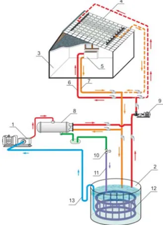
the house consists of fan-coils (5) mounted inside the house and connected to hot water supply (6) and return (7) stands of the heating system. Compressor (1) of the heat pump compresses the gas of refrigerant up to a required condensation pressure, which arises gas temperature up to 75°C to 85°C. The hot gas from compressor (1) is directed into condenser (8) where transfers condensation heat to the heating water, which returns from fan-coils (5) of the heating system. In the condenser, the returned water is reheated, and by circulation pump (9) and stand (6) of the heating system is directed to the fan-coil. The liquid refrigerant passes from condenser (8) through expansion valve (10) of heat pump, where drops its pressure and temperature. Afterwards the refrigerant cooled liquid by pipe (11) enters into the heat exchanger block (12), immersed into the water of underground tank (2). Actually, the heat exchanger block (12) plays the role of the evaporator of heat pump. In the evaporator (12) the cooled liquid refrigerant absorbs heat from stored water and is turned into gas. The gas through knee tube (13) is exhausted again into the compressor (1). The knee tube (13) provides vacuum, which causes pulsation and helps mixture of lubricating oil and refrigerant to return from evaporator into compressor. The last technique is mandatory, as the comp-ressor is installed higher than the evaporator. So, during whole the heating season tank’s water delivers heat to liquid refrigerant for its evaporation and gradually is cooled. As a result at the end of heating season tank’s water completely becomes ice. The compressor (1) sucks refrigerant’s cooled gas from the evaporator (12) and, after compression, pushes it again into the condenser (8). Here the heating system’s water absorbs the condensation heat of the compressed hot refrigerant gas and is heated up to a temperature, required by the heating system of the house. In the evaporator the cooled liquid refrigerant absorbs heat from the stored water and is turned into gas, which finally is sucked into the compressor and the heat pump cycle replicates.
Figure 1. Scheme of the system of heating and cooling universal system.
3. Method for Calculation and Design of
Heating and Cooling Universal System
Sourced by New Type of Heat Pump
The required quantity of water to be stored into the tank can be found from thermal balance of the system:
. . . . . . . . . . . .
.seas hdseas Vairwseas dhwwseas
HP
Q
Q
Q
Q
=
+
+
(1)where: QHP.seas. – total quantity of heat, produced by the new type of heat pump during heating season, to covering multipurpose heat demands of the house, kW.h/seas,
Qhd.seas.–seasonal heating demand of the optimally insulated house, kW.h/seas.,
QV.air.w.seas.- wintertime seasonal quantity of heat for preliminary heating of ventilation fresh air, kW.h/seas.,
Qd.h.w.w.seas.– quantity of heat, needed for preparing of domestic hot water in wintertime season, kW.h/seas.
Should be taken into account that the heat potential of sto-red water is enough for providing the complete evaporation of liquid refrigerant in the evaporator during whole the heating season. From this point of view it is becoming necessary to establish correlation between condensations Qcond and evaporation Qevap heats of the heat pump. To establish correlation between mentioned energies, the following thermal balance of heat pump is analyzed:
. . . evap comp
cond Q N
Q = + (2)
where: Ncomp.- power of the compressor of the heat pump, kW. Division of all components of thermal balance (2) by Qcond. gives the following equation:
. .
. . 1
cond comp cond evap
Q N
Q Q
+
= (3)
As Ncomp./Qcond.=1/
µ
the correlation between evapora-tion and condensaevapora-tion heats is represented by the following formula given in [3]:
− =
µ 1 1 . . cond evap Q
Q , or
−
=
µ
µ 1
. . cond evap Q
Q (4)
where:µ - heat transformation rate or COP of heat pump. The correlation (4) can be represented by the following expression too:
(
)
(
/ 1)
. .= evap
µ
µ
− cond QQ (5)
and climatic conditions of the area. It is assumed that the considered single story family house is located in climatic conditions of Yerevan city Armenia with outside design temperature tout = -19°C. The sizes of the house are the followings: length lb=12m, width bb=12m and height hb=3.1m. The house is optimally insulated with δins=0.19m thick insu-lation material with heat conductivity 0.05 W/(m°C). The value of seasonal heating demand of the considered single-story family house is calculated by the method, developed by Professor Doctor Zohrab Melikyan and Dr. Siranush Egnatosyan, published in [4]. The calculation shows that heating demand of the house makes qhd.=2.625 kW. The seasonal heating demand of the house, calculated with application of heating degree hours of the region makes Qhd.seas.= 9450 kW.h/seas.
Seasonal heat QV.air.w.seas, for preliminary heating of outside ventilation air that can be determined by the following equation:
(
ins outdes)
air wseas airp pers air pers seas w air
V n v c t t Z
Q. . . .= .⋅ . .⋅ . ⋅ .− . . ⋅ρ ⋅ . (6)
where: npers.=5 person – number of habitants of the house,
vair.pers.= 20m3/h per person – hourly volume of outside fresh air for each habitant for ventilation of the house,
cp.air=1.05kJ/(kg°C) – specific heat of the air,
tins.=18°C– temperature of inside air of the house,
tout.des.=-19°C – design temperature of outside air of considered area,
ρair=1.25 kg/m3 – density of the outside air,
Zw.seas.= 3600 h/seas - duration of the wintertime heating season.
Calculation by using above data with formula (6) gives the following value for seasonal heat QV.air.w.seas, produced by the heat pump for preliminary heating of outside ventilation air:
(
18 ( 19))
1.25 3600 17482500 05. 1 20 5 . . .
.airwseas = ⋅ ⋅ ⋅ − − ⋅ ⋅ = V
Q
kJ/seas or 4856kW.h/seas
The hourly thermal productivity of the heat pump for preliminary heating of ventilation air makes qHP.V=1.35 kW.
The value of seasonal quantity of heat, produced for preparing domestic hot water Qd.h.w.w.seas for 5 habitants of the house is determined by the following equation:
(
wfin win)
wseas wp pers w h pers seas w w h
d n g c t t Z
Q.. .. = . .. . .. . − . . . (7)
where: gh.w.pers. =60 kg/day per person – daily quota of hot water per habitant,
cp.w. = 4.18 kJ/(kg C) - – specific heat of the water,
tw.fin.= 43°C – final temperature of hot water,
tw.in.= 6°C – initial temperature of tap water,
Zw.h.seas. = 150 days/seas.
Using above data, calculations were accomplished by formula (7) and following value for seasonal quantity of heat Qd.h.w.w.seas was obtained which produces the heat pump for preparing domestic hot water:
(
43 6)
150 6959700 18. 4 60 5
. . .
.hww⋅seas = ⋅ ⋅ ⋅ − ⋅ = d
Q KJ/seas or
1933 kW.h/ seas.
Hourly thermal productivity of the heat pump for ventilation purpose is QHP.d.h.w. =1933 kW.h /3600 h=0.537
kW.
It is clear that quantity of heat, produced in the condenser of heat pump is the sum of seasonal heat productions for the mentioned heat demands of the house: 1- quantity of seasonal heat for heating of the house; 2 - quantity of seasonal heat for preliminary heating of outside ventilation air and 3- quantity of heat, produced for preparing domestic hot water.
So, for covering the multipurpose heat demands of the house total thermal productivity of the heat pump should be taken equal to the following sum:
qHP=qhd.+qHP.V+qHP.d.h.w=2.625+1.35+0.537=4.512kW (8)
Respectively heat production of the heat pump during heating season for simultaneous covering of heat demands for heating, ventilation and domestic hot water of the house makes:
QHP.seas. = 9450 + 4856+1933= 16 239 kW .
h/seas
The seasonal production of heat by the heat pump is determined by the following equation:
(
)
(
)
(
1)
3600 . . . . . .. −
+ − ⋅
=
r
ice fin t w in t w w p w r seas HP
t t c G Q
µ
β µ
(9)
where: QHP.seas – total quantity of heat, produced by heat pump during heating season, kW.h/seas,
tw.t.in.=20 C to 25 C–initial temperature of tank’s water at the beginning of winter season, assumed equal to summertime final temperature of water which returns from fan-coils of the house with summertime inside temperature tins.=25°C,
tw.t.fin.=-5 C– final temperature of ice at the end of wintertime heat supply season,
ρice= 334 kJ/(kg C)- water ice fusion heat.
Formula (9) can be represented in the following form, which allows determining the quantity of water Gw, kg which is subject to be stored in the underground tank:
(
)
(
)
(
pw win wfin ice)
r
r seas HP w
t t c
Q G
β
µ − µ+
− ⋅ =
. . .
.
. 1
3600
(10)
Volume of underground tank is evaluated by the following expression:
w w
k G
Vtan =1.07 /
ρ
(11)where: 1.07–coefficient which indicates that the volume of ice grows in 7% over the water volume,
ρw = 1000 kg/m3 - density of water.
compliance with heat supply system’s temperatures. For this purpose the thermodynamic cycle of heat pump which operates with ecologically friendly refrigerant “R-134a” in the range of condensation temperature tcond = 65°C and evapora-tion temperature tev.=−7°C was analyzed. For finding the right volume of the water – ice storage underground tank, in the
formulas (9) and (10) the real transformation rate
µ
r ofsuggested heat pump should be used. The value of
µ
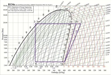
r, wasfound by the help of heat pump’s thermodynamic cycle, which is plotted on diagram (i – logP) of the Freon “R-134a” [6]. The diagram (i– logP) with heat pump cycle is shown on Fig. 2.
Figure 2. Thermodynamic cycle of developed water-ice storage universal heat pump.
line “4-1a” – Evaporation process of refrigerant in the evaporator of the heat pump; line “1a-1”- Superheating of gas refrigerant in intermediate heat exchanger; line “1-2b”- Adiabatic ideal process of gas compression in compressor; line “1-2”- Adiabatic real process of gas compression in the compressor of heat pump; line “2-2a”- Superheated gas cooling process in condenser of heat pump; line “2a-3a”- Gas condensation process in condenser of heat pump; line “3a-3”- Gas condensate sub cooling process in intermediate heat exchanger; line “3-4”- Gas condensate’s isenthalpic cooling process in expansion valve i1a=394 kJ/kg; i1=403
kJ/kg, i2=467 kJ/kg, i2b=448 kJ/kg, i2a=428 kJ/kg, i3a=296 kJ/kg, i3=287 kJ/kg, l=64 kJ/kg, qc =171 kJ/kg
As a rule the following formula is used for determining the real value of heat pump’s transformation rate
µ
r:(
i2 i3a) (
/i2 i1)
r = − −
µ (12)
where: i2−i3a -specific quantity of condensation heat of the refrigerant, kJ/kg,
i2–i1 - specific quantity of energy consumed by compressor in polytrophic compression process, kJ/kg.
The values of refrigerant enthalpies are taken from the cycle of heat pump (Fig. 2) and according to them the real value of µr, is calculated by the fraction (12):
67 . 2 64 / 171 403 467
296 467
1 2
3
2 = =
− − = − − =
i i
i
i a
r
µ
It is clear that large difference between condensation tcond and evaporation tev temperatures brings to the lower energy efficiency
µ
rof heat pump. In its own turn the value ofµ
r conditions the quantity of water Gw, to be stored in the tank, which according to (9) and (10) makes:(
)
(
)
(
)
79593598 . 1226 97628868 334
5 25 18 . 4 67 . 2
3600 1 67 . 2 239 16
= =
+ + ⋅
⋅ − ⋅ =
w
G kg.
Respectively the volume of the tank which contains only water is Vw.tank = 79.59 m3. Taking into account that the volume of the ice in 1.07 times is bigger than the volume of water, the real volume of the tank should be taken:
164 . 85 59 . 79 07 . 1
tank = ⋅ =
V m3.
Above analysis proves that lower transformation rate of heat pump conditions lower quantity of water to be stored in the tank. Consequently, the required volume of the tank, Vtank, m3 becomes smaller. Diameter of the cylindrical water-ice storage tank dt, m, for wintertime heating regime of the house is determined by the following formula and makes:
m h
V d
t t
t 6.0
3 14 . 3
164 . 85 4
4 =
⋅ ⋅ = ⋅ =
π (13)
The evaporator of liquid refrigerant which is immersed in tank’s water can be assembled with heating appliances of type M-140 [7] consisted of multiple sections, made of wrought iron. The sections are mounted in series and are installed on special supports located in the very middle part of underground water storage tank. The heat transfer rate of each section is ksec=7W/m2°C and the heat transfer surface is
fsec.=0.310 m2[7]. The inlet of the first section is connected with liquid refrigerant pipeline and the outlet of the last in row section is connected with exhaust pipeline of compressor as shown in Fig. 3.
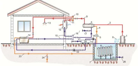
Figure 3. Finally completed structural scheme of universal heating and cooling system of a house with new type of heat pump.
1-compressor, 2- pressed hot gas pipeline, 3- condenser, 4-liquid refrigerant pipe, 5-expansion valve, 6-evaporator, 7-water storage underground tank, 8- knee pipe, 9-hot water supply pipeline, 10- hot water collector, 11-hot water pipe to ventilation air heater, 12- air heater, 13-domestic hot water sprayer, 14-fan-coil, 15- cooled water return pipelines,16-cooled water collector, 17-tap water to condenser, 18-icy water suction pipe from water tank to auxiliary vessel (20), 19-icy water sucking pump, 20-auxiliary vessel, 21- tap water supplying pipe, 22-pump of cold water mixture to fan-coil, 23-warmed water return pipeline from fan-coil to water storage tank, 24- drainage pipeline for segregation of the half of water returning from fan coil to storage tank, 25 – support, 26- tank’s drainage pipe.
Heat exchange required total surface of the evaporator is determined by the following formula:
(
)
(
win wfin)
ev r
HP r ex
h
t t k
q F
. . . .
.
1 − ⋅ ⋅
− =
∑
µ µ (14)where: qHP =4.512kW- hourly thermal productivity of the heat pump needed for covering the multipurpose heat demands of the house, which was determined above by formula (8)
kev.=ksec.=0.007kW/(m 2
°C).– heat transfer coefficient of evaporator, immersed in the water of underground tank [7].
Calculation by (14) shows that the evaporator’s required total surface should be:
(
)
(
)
14.4 523 . 054 . 7 5 23 007 . 0 67 . 2
512 . 4 1 67 . 2
.
. = =
+ ⋅
⋅ − =
∑
Fhex m2
The number of evaporator sections is determined by the
following expression: n=
∑
Fh.ex./fsec.=14.4/0.310=47items, which are joint each to other in series.4. Operation of the System in Summer
Cooling Regime and Method for
Calculation
It was claimed above, that in summer cooling season there is no need in operation of the heat pump, as the cooling source is ready in form of the ice, collected during heating season on the surface of the evaporator, located in the underground water storage tank. In the beginning of summertime air conditioning season, because of heat gains from the environment, the ice starts gradually melting and the pump ((19) Fig. 3) supplies icy water to fan-coils of the house. For increasing the thermal potential of water, which is supplied into fan-coils of the house, on the top of the tank during whole the summer cooling season is poured tap water with temperature ttap.w= +10°C and quantity gw.tap= 22 kg/h which is mixed with the same quantity of icy water with temperature ticy.w.=0°C. The water mixture is collected into an auxiliary vessel (see (20) Fig. 3) and gets a temperature tw.mix which is determined by the following equation:
(
)
(
)
5159200 10 0 79593
. . .
. =
+ =
+ =
mix w
w tap w icy w mix w
G t t G
t °C (15)
where: Gw.mix=2⋅Gw=2x79593kg=159200kg – quantity of prepared water mixture with temperature tw.mix = 5°C.
Whole the water mixture with the mass Gw.mix=159200 kg and temperature tw.mix= 5°C by the pump ((22) Fig. 3) during cooling season gradually is supplied from auxiliary tank to fan-coils where it absorbs supplemental heat in quantity of seasonal cooling demand Qcd.seas.=3490 kW.h/seas, which is determined by the method published in [8]. As a result the inside air of the house is cooled up to summertime comfortable tins=25°C temperature. Simultaneously the water in fan-coils is heated from tw.mix.in.= +5°C to a final temperature
tw.mix.fin which is determined by the following formula:
9 . 23 18 . 4 159200
3600 3490 5
. . . . .
. =
⋅ ⋅ + = +
=
w p mix w
cd in mix w fin mix w
c G
Q t
t °C (16)
5. Annual Consumption of Energy by
Heating and Cooling Universal System
The suggested system round year consumes electricity. In wintertime heating season the consumers of electricity are the compressor of heat pump and water circulation pumps. In summer cooling period only water circulation pumps are in work and consume electricity. So, the energy total consumption during a year ΣNH-C.syst, makes the following sum:
year WP w HP syst C
H N N
N Σ
Σ − . .= . int.+ (17)
where: NHP.wint – heat pump’s energy consumption in winter season, kW.h,
year WP N
Σ - energy annual consumption by water circulation pump, kW.h.
Heat pump’s compressor consumption of energy during heating season NHP.wint., kW.h is calculated by the following fraction: HP r seas cond w HP Q
N . int.= . ./µ. (18)
AsQcond.seas. =QHP.seas., the formula (18) is represented in the following form:
HP r seas HP w HP Q
N . int.= . ./µ. (19)
As was mentioned above, that the value of seasonal heat production of the heat pump makes: NHP.w.seas.=16 239 kW
. h and the real value of transformation rate of heat pump is equal toµr.HP =2.67. Therefore, winter time seasonal consumption of electricity by the heat pump makes:
6082 67 . 2 / 16239 . int
.w = =
HP
N kW.h/seas
Round year consumption of electricity by water circulation pumps is determined by the following sum:
. . . . .
.year phsys pcoolsys
WP N N
N = +
Σ
(20)
where: Np.h.sys - heating system’s energy seasonal consumption by hot water circulating pump, kW.h;
Np.cool.sys.- cooling system’s energy seasonal consumption by cold water circulating pump, kW.h.
Seasonal consumption of energy by heating system’s pump is determined by the following production:
. . . . . .
.hsys hsw hs
p V P
N = ⋅∆ (21)
where: Vh.s.w – volume of the heating water, circulating by circuit “condenser –fan coil” during heating season, m3/seas;
. .s h
P
∆
- pressure developed by water pump to overcome hydraulic resistance of heating system’s pipelines, Pa.As the anticipated flow regime is laminar, the value of
. .s h
P
∆
is determined by Darcy – Weisbackh following equation [9]: 4 . 1 2 2 . . ⋅ ⋅ = p p w w s h d lP
λ
ρ
ω
∆
(22)where:λ- friction factor in water supply and return direct pipelines;
w = 1m/s- velocity of heating water in supply and return pipelines;
lp = 60 m – total length of heating water supply and return pipelines;
dp = 0.025m- diameters of heating water supply and return pipelines;
1.4– approximate total factor of supplemental local hydraulic resistances of heating water supply and return pipelines’ fittings [10].
The friction factor λfor laminar regime is determined by the help of following ratio:
Re 64 =
λ (23)
The Reynolds number Re is determined by the following fraction:
ν ωw⋅dp =
Re (24)
where:ν - kinematic viscosity of water, ν =0.00001416 m2/s [11].
Subject to the above characteristic values for Re and
∆
P
h.s.the following quantities are calculated:
1765 00001416 . 0 025 . 0 1
Re= ⋅ =
The obtained value of Re =1765 shows that the water flow
regime is really laminar. The pressure
∆
P
h.s., to be developedby water pump, according to (22) makes:
60918 4 . 1 025 . 0 60 2 1 1000 1765 64 4 . 1 2 Re
64 2 2
. . ⋅ = ⋅ = ⋅ ⋅ = p p w w s h d l
P ρ ω
∆ Pa
The volume of water, circulating through the circuit “condenser –fan coil” of heating system Vh.s.w., m3/seas during heating season, is determined by the following formula and makes:
(
)
(
)
27130 60 18 . 4 1000 3600 9450 3600 . . . . . . . . . ⋅ − = ⋅ = − ⋅ ⋅ = ret w l sp w w p w seas hd w s h t t c Q V
ρ m3/ seas.
Therefore, seasonal consumption of energy by heating system’s water circulation pump will be:
16508778 60918 271 . . . . . . .
.hsys = hsw⋅ hs = ⋅ =
p V P
N ∆ J or
Np.h.sys. = 16508 kJ/3600= 4.6 kW.h/seas.
mixture with temperature +5°C and volume 159.2 m3 circulates through the circuit “auxiliary tank-fan-coils - auxiliary tank”. In fan-coils, the water mixture absorbs inside surplus heat in quantity of seasonal cooling demand of the house Qcd.seas = 3490 kW.h/seas. As a result, the house is cooled up to summertime design comfort 25°C temperature and the water in fan-coils is warmed from 5°C up to 23.9°C and is returned from fan-coils into water storage tank to be used as low temperature heat source for heat pump in the next heating season. For this purpose the circulation pump during cooling season consumes electricity Np.cool.sys., which is calculated in the following way:
9698145 60918
2 . 159 . . . . . . .
.coolsys = csw∆ cs = ⋅ =
p V P
N J or 2.7 kW.
h/seas
To check the adequacy of the icy water cooling potential Qcool.pot to the seasonal cooling demand of house the following equation is used:
(
)
5 . 4251 3600
23 18 . 4 159200 3600
0 23
. .
. =
⋅ ⋅ =
−
= w pw
pot cool
c G
Q kW.h.
The last calculation proves that the cooling potential of the water is enough and even more for covering the seasonal cooling demand of the house which makes Qcd.=3490 kW.h per season. Therefore, the system can operate round year accurately.
Annual energy consumption by heating and cooling uni-versal system sourced by new type of heat pump totally makes:
3 . 6089 7 . 2 6 . 4 6082 .
. = + + =
∑
NH−Csys kW.h/yearEnergy annual consumption referred to 1m3 of the house makes 6089.3/500 m3 = 12.2 kW.h/m3 per year. This fact proves the high energy efficiency of developed technology.
6. Conclusions
The suggested water-ice storage heat pump heating and cooling universal system of houses can find wide application because of rather simple structure and high energy efficiency. The proposed method for calculation and design can be accepted by designing enterprises to use it in practice of developing advanced technological solutions in the field of heat and cold supply of buildings.
The water storage tank does not need thermal insulation, as it is located in the ground, which plays the roles of both insulation and partial heat source.
The 6089.3 kW.h/year annual consumption of electricity for heat and cold supply of a house with 500m3 of volume (or 12.2 kW.h/m3 per year) prove the high energy efficiency of suggested system.
As the system round year operates by energy regeneration principal, energy wastes are negligible, as a result the system provides highly efficient wintertime heating and almost free of charge summertime cooling.
Compared with open and closed loop geothermal heat pumps, developed universal heat pump does not cause damages e.g., erosion of ground, sedimentation, toxic
antifreeze solutions and because of compactness can be widely implemented in both urban and rural busy areas.
The proposed method and formulas for determination of correlation between high and low potential heat sources is helpful for heat pump designers.
Bigger the served building and colder and longer the heating season, bigger the volume of water storage tank and vice versa.
In most cases the volume of the underground water storage tank makes about 9.5 to15% of the volumes of served buildings and does not occupy free areas of the buildings’ yards.
In case of successful results of testing and confirmation of anticipated results the suggested system probably will squeeze out and replace well known open and closed loop geothermal heat pumps.
References
[1] Karl Ochsner, Geothermal heat pumps: a guide for planning and installing. Earthscan, London, Sterling, VA, 2007, 164pp. [2] Zohrab Melikyan, Developing of heating and cooling local heat
pump and method for design. Journal of Buildings and Sustainability. Vol.1, No.1, 2016, 47-55pp.
[3] Melikyan, Z. A. Heating–Cooling of Buildings. Efficiency of Conventional and Renewable Technologies LAP Lambert Academic Publishing, Germany, 2012, 344 pages ISBN-978-3-8443-1939-2.
[4] Melikyan, Z. A., Egnatosyan, S. M. (2015). Residential Buildings: Heating Loads. Encyclopedia of Energy Enginee-ring and Technology, Second Edition. Taylor and Francis: New York, 1629-1636pp. Published online: 17 Jun. DOI: 10.1081/E-EEE2-120051988.
[5] Egnatosyan, S. M. (2009). Hybrid System for Heating and Cooling of Houses with “Air to Air” Heat Pump and Heating Boiler. The 4th International Renewable and Clean Energy Conference Yerevan, p.41.
[6] Wilson, Basu, ASHRAE Transaction Freon “R-134a” 1988. [7] V. F. Vasilev, U. V. Ivanova , I. I. Sukhanova: textbook
СПбГАСУ. – СПб., 2010. – 72 p. ISBN 978-5-9227-0171. [8] Melikyan, Z. A., Ali Abd Elhaleem A. F. Assessment of a
modified method for determining the cooling load of residential buildings. International Journal Elsevier V.35, 2010 England pp.4726-4730.
[9] Marriott, M. J., Featherstone, R. E., Nalluri, C. 2009. Civil Engineering Hydraulics. 5th Edition, University of East London, J, Wiley & Sons, 424p. ISBN-10: 1405161957, ISBN-13: 978-1405161954.
[10] Kopko, V. M. 2014. Heat supply and ventilation. 2nd edition, Publishing house “ACB”, Moscow, 336p, ISBN 978-5-93096-890-6.