Chain Coding and Pre Processing Stages of Handwritten Character Image File
Azizah Suliman
Department of Systems and Network, College of IT Universiti Tenaga Nasional
Kampus Putrajaya, 43009 Kajang, Selangor [email protected]
Mohd. Nasir Sulaiman, Mohamed Othman,
Rahmita Wirza
Fakulti Sains Komputer dan Teknologi Maklumat Universiti Putra Malaysia
43900 UPM Serdang, Selangor [email protected], [email protected]
Abstract – In this paper detailed descriptions of the algorithms used in the pre-processing and feature extraction phases of an offline handwritten character are discussed. In classifying handwritten characters, the stages prior to the classification phase play a role as major as the classification itself. There are many pre-processing functions and methods that can be used and different research works will use different methods. This paper discusses in detail some of the algorithms used in the pre-processing stages of an offline handwritten character image file. This paper serves as part of the whole research work that aims at recognizing handwritten characters. The whole research presents a hybrid approach of HMM and Fuzzy Logic in the field of handwritten character recognition. Fuzzy Logic is used in the classification phase while HMM is used in the process of extracting features for the preparation of linguistic variables of the fuzzy rules. However, only the pre-processing stages as employed by the research are described here. The pre-processing phase starts from reading in the input file, the process of binarization, reference line estimation and thinning of the character image for further use in the next stage of the feature extraction and recognition process. Each of the pre-processing stages and the chain coding process will be described in detail giving improvised algorithms, and examples of the processes on existing samples from the database shown. Where comparing experiments with other methods is done, the experimental results are given.
Keywords – pre-processing; feature extraction; chain-coding; binarization; thinning; handwritten character
I. INTRODUCTION
The attempt to imitate the human ability to read and recognize handwritten matter by a machine is the objective of optical character recognition (OCR), or sometimes specifically referred as handwritten character recognition (HCR) research.
Handwriting recognition is the task of producing the symbolic form, from the stored information of the handwriting data. Handwriting data is captured and stored in its digital format either by scanning the writing on paper or by writing with a special pen on an electronic surface such as a digitizer combined with a liquid crystal display. The two approaches are respectively distinguished as off-line and on-line handwriting. On-line systems for handwriting recognition are available in hand-held computers such as PDAs with acceptable performance [1]. Off-line systems are less accurate than on-line systems due to their less
informative data capturing device, which is usually the scanner. However, they are now good enough that they have a significant economic impact in specialized domains such as interpreting handwritten postal addresses on envelopes and reading courtesy amounts on bank cheques [1].
II. HANDWRITTEN CHARACTER RESEARCH According to Arica and Yarman-Vural in their review of character recognition (CR), the CR systems have evolved in three stages [2]. The early stage is in the period of 1900-1980. The beginning of OCR was said to have started with the objective of developing reading machines for the blind. In these early systems of automatic recognition of characters, area of concentrations are either in machine-printed text or upon small sets of well-distinguished handwritten text or symbols. In the second period of development in the era of the 1980s to 1990s, the explosion of information technology has helped a rapid growth in the area of OCR. The CR research was focused basically on the shape recognition techniques without using any semantic information. Although an upper limit in the recognition rate was achieved, it was not sufficient in many practical applications. The 1990s and onwards are referred as the advancements era, where the real progress in OCR systems has been achieved. In the beginning of this period, image processing and pattern recognition techniques were efficiently combined with artificial intelligence (AI) methodologies. Complex algorithms for character recognition systems were developed. There is, however, still a long way to go in order to reach the ultimate goal of machine simulation of fluent human reading, especially for unconstrained on-line and off-line handwriting [2].
electronic Journal of Computer Science and Information Technology (eJCSIT), Vol. 2, No. 1, 2010
A. Suliman, M. N. Sulaiman, M. Othman and R. Wirza, Chain Coding and Pre Processing Stages of Handwritten Character Image File 7 Figure 1. Tasks of a handwritten character classifier
III. THE PROPOSED SYSTEM STRUCTURE
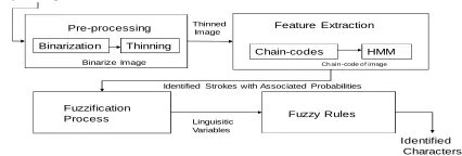
The structure of the whole system is illustrated in Fig. 2. The task of recognizing and classifying the characters from an image file, goes through a few processes as illustrated by the figure. The input image file is preprocessed using minimum preprocessing functions like binarization and thinning. The thinned image will then undergo a feature extraction process of chain-coding. The chain-coded image kept in a file, is then passed through a Hidden Markov Chain. The HMM will be processing the chain-codes and the output produced would be the identified strokes and their associated log-likelihoods. These log-likelihood values are then converted to probabilities and pass through a fuzzification process producing meaningful linguistic terms for the variables. The linguistic variables will then be used by a set of fuzzy rules to classify the character accordingly.
Feature Extraction Input Images
Pre-processing
Chain-codes HMM
Fuzzification
Process Fuzzy Rules
Binarization Thinning
Binarize Image Ch ain -code o f image
Thinned Image
Identified Strokes with Associated Probabilities Linguisitic
Variables
Identified Characters
Figure 2. System structure
A. Problem Statement
As the problem of handwritten character recognition deals with lots of variations and complexity of data, most of the time to use a purely statistical method would be too risky. In 1965, Zadeh [2] introduced a modified set theory namely known as fuzzy sets. Fuzzy logic deals with fuzzy sets that classify using unsharp boundaries. Since the data of some of the handwritten characters are sometimes vaguely
distinguishable, a fuzzy inference seems to be a very logical way to deal with the recognition. Fuzzy rule-based systems utilize linguistic variables and changing numerical data of an image into its linguistic form can be very challenging. Furthermore, one of the major drawbacks of fuzzy logic is the lack of learning capabilities, unlike in neural networks and HMM, where its parameters can be trained. There have been efforts in this area where neuro-fuzzy systems are introduced.
HMM has been used in a lot of the handwritten character/word recognition as a classifier of characters/words and as a hybrid approach with other methods [3, 4]. In this research project, HMM will instead be used in the preparation of linguistic variables of a fuzzy rules recognizer.
In the process of being recognized and classified, the raw data of the handwritten character in the form of an image file will be going through 3 stages as previously mentioned and also as illustrated in Fig. 1. As the purpose of this paper is to detail out the pre-processing phase it would be best for the problem statement of this phase to be explained. The main objective of this phase is to prepare the data file for the subsequent phases. Since this research will be using fuzzy rules to classify the handwritten character, a certain requirement has to be met: the fuzzy rules will be needing linguistic variables for the purpose of classifing the character. This would be in the form of strokes and lines that form the character. It was also identified that HMM will instead be used in the preparation of linguistic variables. Since the HMM will be processing the chain-codes of the character, the pre-processing phase will be gearing towards the preparation of the input for the HMM. It would be the objective of this phase to produce a chain-code that would best represent the strokes and lines that made up the character.
IV. PRE-PROCESSING PHASE
The raw data of handwritten characters, no matter how it is acquired, will be subjected to a number of preprocessing steps to make it useable. The preprocessing phase aims to extract the relevant textual parts and prepares them for segmentation and recognition. The main objectives of preprocessing are i) noise reduction, (ii) normalization of data and (iii) compression in the amount of information to be retained. In noise reduction alone there are hundreds of available techniques which can be categorized into three major groups of filtering, morphological operations and noise modeling ([3], [4]). Filters can be designed for smoothing [5], sharpening [6], thresholding [7], removing slightly textured background [8] and contrast adjustment processes [9]. Various morphological operations can be designed to connect broken strokes [10], decompose the connected strokes [11], smooth the contours, prune the wild points, thin the characters [12], and extract boundaries [13]. Pre-Processing Phase
Feature Extraction Phase
Classification Phase Input Image File
In this research work a minimal number of preprocessing processes are used. The preprocessing steps are shown in Fig. 3. An image file of handwritten character will first be read and binarized. Then reference lines of upper and lower base line of the character will be estimated. The estimation of the upper and lower base line will be used to classify the characters into its three groups of either ascenders (e.g h, l, t, f, d, b), descenders (e.g. g, p, q, y) or neither (e.g. a, c, e, i, m, n etc.) . The subsequent sections will explain
pre-processing phase undertaken in this research. Pre-processing Steps
Step 1: Binarize the character image.
Input: An image file of the character in .bmp format Results: A matrix of the character image in 0’s (for background) and 1’s (for the foreground that makes up the character contour).
Step 2: Estimate reference line to classify the three groups of characters (ascenders, descenders, neither).
Input: The character matrix from Step 1. Results: A classification of the character into to be used as one of the character features in the fuzzy inference system.
Step 3: Thin the image into edges of one pixel thick. Input: The character matrix from Step 1.
Results: A character matrix with all (or at least most of) its edges with one pixel thickness only.
Figure 3. Pre-processing steps
A. Binarization
When an image is captured, it is frequently
form of pixel density value, which means each pixel has value between 0 and 255 (for a grayscale image). Many researchers choose to work with a binarized
the grey values will be thresholded and converted to either ‘0’ for white (background) or ‘1’ for black (foreground). This process is known as binarization.
The method used to binarize is known as thresholding. In thresholding, the gray-scale or color images are represented as binary images by picking a threshold value. The two categories of thresholding are global and local thresholding. In global thresholding, one threshold value is used for the entire document image which is often based on an estimation of the background intensity level with that of the image using an intensity histogram [11]. Local or adaptive thresholding use different values for each pixel according to the local area information [14]. Local thresholding is commonly used in works that involve images that are of varying level of intensities, such as pictures from satellites cameras or scanned
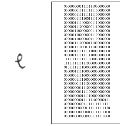
For simple images like handwriting, where the characters are written on a white background, using a global threshold would suffice to distinguish the background and the foreground. Fig. 4 displays an image of the character ‘e’ in its image file format of .bmp and the same char
had been binarised and saved in a text (.txt) file.
In this research work a minimal number of preprocessing processes are used. The preprocessing steps are shown in . An image file of handwritten character will first be of upper and lower base line of the character will be estimated. The estimation of the upper and lower base line will be used to classify the characters into its three groups of either ascenders (e.g h, l, t, g. g, p, q, y) or neither (e.g. a, c, e, i, m, n etc.) . The subsequent sections will explain further the
processing phase undertaken in this research.
An image file of the character in .bmp format A matrix of the character image in 0’s (for background) and 1’s (for the foreground that makes up the
ine to classify the three groups of characters (ascenders, descenders, neither).
The character matrix from Step 1.
A classification of the character into the 3 groups; o be used as one of the character features in the fuzzy
edges of one pixel thick. The character matrix from Step 1.
A character matrix with all (or at least most of) its
frequently stored in the form of pixel density value, which means each pixel has a scale image). Many d image where all and converted to either for black (foreground). The method used to binarize is known as thresholding. scale or color images are represented as binary images by picking a threshold value. two categories of thresholding are global and local sholding. In global thresholding, one threshold value is used for the entire document image which is often based on an estimation of the background intensity level with that of nsity histogram [11]. Local or adaptive thresholding use different values for each pixel according to the local area information [14]. Local thresholding is commonly used in works that involve images that are of varying level of intensities, such as scanned medical images. For simple images like handwriting, where the characters are written on a white background, using a global threshold would suffice to distinguish the background and the age of the character ‘e’ in its image file format of .bmp and the same character after it
in a text (.txt) file.
Figure 4. The character “e” in its image file format (.bmp) and in its binarized text file format
B. Reference Line Estimation
One preprocessing technique that has been particularly helpful in determining features in a word is reference line estimation. Bozinovic and Srihari [15] refer
task of locating such lines as the lower line, lower baseline, upper baseline and the upper line. To determine these lines, an approach based on the one proposed by Bozinic and Srihari [15] is considered. The approach
word image and in such images the reference lines are more distinguished, as the inputs are larger.
(a) (b)
Figure 5. Examples of characters after line referencing (a) an ascender, (b) a descender, and (c) neither an a
With a little improvisation, a implemented for character images
referencing used in this research are shown in F
first step would be to generate a horizontal density histogram for the character image. This was done based on a black pixel count in each row (horizontal direction at each position on the y-axis). From the top, the first row count that has more than a minimum threshold (in this case a pixel count of 2 is used) and an upp
traversing from the bottom of the image or the last row in
000000000011111111000000000 000000000111111111100000000 000000001111111111100000000 00000000111110011111000000 000000011110000001110000000 000000011100000001110000000 000000111000000001110000000 000000111000000011100000000 000000111000000011100000000 000000111100000111000000000 000000111100001111000000000 000000011111111110000000000 000000111111111110000000000 011111111111111000000000000 011111111111110000000000000 001011111111000000000000000 000000011111000000000000000 000000001111000000000000000 000000001111100000000000000 000000000111110000000000000 000000000011110000000000000 000000000011111000000000000 0000 000000000001111111000000111 000000000000111111111111111 000000000000001111111111110 000000000000000111111111100 000000000000000001111110000
The character “e” in its image file format (.bmp) and in its text file format
One preprocessing technique that has been particularly helpful in determining features in a word is reference line estimation. Bozinovic and Srihari [15] referred to it as the task of locating such lines as the lower line, lower baseline, upper baseline and the upper line. To determine these lines, proposed by Bozinic and Srihari [15] is considered. The approach, however, was for a word image and in such images the reference lines are more
are larger.
(c)
Examples of characters after line referencing (a) an ascender, (b) a descender, and (c) neither an ascender nor descender.
a similar approach was s. Examples of the line referencing used in this research are shown in Fig. 5. The first step would be to generate a horizontal density the character image. This was done based on a black pixel count in each row (horizontal direction at each axis). From the top, the first row count that more than a minimum threshold (in this case a pixel count of 2 is used) and an upper line is found. Next, traversing from the bottom of the image or the last row in
electronic Journal of Computer Science and Information Technology (eJCSIT), Vol. 2, No. 1, 2010
A. Suliman, M. N. Sulaiman, M. Othman and R. Wirza, Chain Coding and Pre Processing Stages of Handwritten Character Image File 9 the image, the first row count that is more than the
minimum threshold would indicate the lower line. Estimating the middle line is slightly more complex. First we have to assess roughly if the image is denser in the lower or the upper zone. This is estimated by first determining the mid line, i.e. the average of upper line and lower line. Then the pixels density of the upper and the lower zones are calculated. If the upper zone is denser then we start traversing from the mid line to the upper line, otherwise we traverse from the mid line to the lower baseline. Taking a threshold T, that is the average density of the character, we scan through the density vector and the first line that has a density value that is lower than T, would be considered as the middle line. The middle line produced was a better option than the mid line gotten from the average of the lower and the upper lines. This estimate of the middle line has proven favorable enough for the next step.
Once the upper, middle and lower lines have been placed, the character will be heuristically categorized into either an ascender, a descender or neither. The algorithm for the heuristic technique used in the research is given in Fig. 6. The grouping of the characters into the 3 groups are utilized directly by the recognition phase, and if grouped correctly it would have scoped down the classification phase from the 26 possibilities (26 alphabets of a .. z ) to about a third of the original possibilities.
The heuristic technique was compared to an HMM model created to group the character using the vertical density of the image. Relying on the fact that some of the characters in a certain group would be denser in the upper zone than the lower zone and so on, the result of the grouping using the heuristic method is given in Table 1. The heuristic technique yields a correct grouping rate of 70.35%, while the HMM technique yields a correct grouping rate of 64.3%.
Figure 6. Algorithm for grouping characters
TABLE I. CONFUSION MATRIX OF THE THREE GROUPS OF CHARACTERS
Actual Group Classified group
Neither Ascenders Descenders Total
Neither 94.39 3.57 2.04 100.0
Ascender 21.43 63.09 15.48 100.0
Descenders 27.38 19.05 53.57 100.0
C. Thinning
There are a number of algorithms available for the thinning process. Thinning algorithms have to satisfy among others the following two constraints:
• Connectivity must be maintained at each iteration. Removal of border pixels must not cause discontinuities.
• The end of the thinned shape limbs must not be shortened.
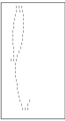
Since the image of handwritten words are relatively small and less elaborate and less convex than an image of other objects, a slightly simpler version of a thinning algorithm would suffice. The thinning process used in this research is a one pass thinning algorithm that has been slightly modified to ensure connectivity and at the same time to repair any repairable discontinuities. An example of a binarized image of the same character ‘e’ as in Fig. 4, where it is shown before the thinning procedure, is shown again in Fig. 7 after it had been thinned.
Figure 7. A thinned binarized image of ‘e’
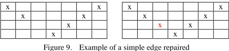
With the process of thinning where pixels are removed, sometimes the image can get broken or disjointed. To cater for such cases, images that had been thinned will be passed through a special function that would check and repair simple disjointed edges caused by thinning. The code and example of a repaired edge are shown in Fig. 8 and Fig. 9.
Figure 8. Codes for repairing simple disjointed edge
for (j=-1; j <= 1; j++)
if (image[rw+1][cl+j]== (unsigned char)black) pts1++; for (j=-1; j <= 1; j++)
if (image[rw+2][cl+j]== (unsigned char)black) pts2++; if ((pts1 == 0) && (pts2 > 0))
image[rw+1][cl] = (unsigned char) black; Gap1 = upper line – middle line
Gap2 = middle line – lower line If Gap1 is small or Gap2 is small Alphabet is Neither else
if density in upper zone > density in lower zone Alphabet is Descender
Else
Alphabet is Ascender
1 1 1 1 1 1
1 1
1 1
1 1
1 1
1 1
1 1
1 1
1 1
1 1
1 1
1 1 1 1 1 1
1
1
1
1
1
1
1
1
1 1
x x x x
x x x x
x x x
x x
Figure 9. Example of a simple edge repaired D. Checking for noise and dots
The database used in this research has not undergone any cleaning process. However, only small noises as produced by the writing itself rather than the quality of the scanner can be observed in the data. In order not to create confusion for the next process of chain-coding, the character data will be scanned through and removed of any possible noise.
This process will also unfortunately remove the dots of the characters “i” and “j”. Since the dots will not be taken as distinguishing features in the fuzzy rules to classify these two characters, retaining the dots of these characters will not be of any value, hence the algorithm as proposed is implemented. The algorithm is found to be useful of getting rid of small and other insignificant connected components. The algorithm used to remove the small isolated dots and lines is given in Fig. 10.
/* To count the density of the connected components in the image. Keep track of its starting row, end row and sum up the pixel density of every row in the connected component. */
i = first line; j = 0;
do { While horizontal density of the line[i] > 0 Group[j].start = i;
Group[j].density += density of line[i]
i++
End while
j++;
Group[j].stop = i--; } while i <= last line in the image;
/* Now check height and density of the connected component and clear all that have height and density below threshold values */
for i = 0 till j-1
{ Height = Group[i]. start – Group[i].stop If Height < 3 and Group[i].density < 8 for m = Group[i]. start till Group[i].stop Clear all black pixel at row m in the image }
Figure 10. Algorithm for removing small dots or lines (noise) In summary, the preprocessing tasks that were employed in this research work are mainly binarization, thinning, removing of noise and dots. While in the phase of binarization, the first feature extracted is the grouping of the character into the following categories of: ascender, descender and neither. Now that the handwritten character image has been preprocessed, the nest step is to extract as many features needed for the use of classification. The next section will discusses the feature extraction phase in more detail.
V. FEATURE EXTRACTION PHASE
The feature extraction phase in a handwriting recognition system is agreed by many [2][16][17] to hold a very important role. Feature extraction can be defined as the process of extracting distinctive information from the matrices of digitized characters. In OCR applications it is important to extract those features that will enable the system to discriminate between all the character classes that exist. A suggested reading on the survey of feature extraction methods for handwriting recognition would be Oh, Lee and Suen [18].
Geometrical and topological representation is one of the many feature extraction methods used in the OCR research. This method has proven to be the most popular feature extraction method amongst researchers [19]. This type of representation is able to encode some knowledge about the structure of the object, or may provide some knowledge as to what sort of components make up that object. There are hundreds of topological and geometrical representations than can be grouped to a few categories [2].
One popular category in geometrical and topological representation of features is by extracting and counting topological structures. Common primitive structures that are searched from a character or word image, are strokes which may be as simple as lines and arcs or as complex as curves and splines. Characters and words can be successfully represented by extracting and counting many topological features such as the extreme points, maxima and minima, cusps above and below a threshold, openings, cross points (x), branch points (T), line ends, loops and many more [20][21].
Coding is a category where the strokes of the character are mapped into chain-codes. One of the most popular coding schemes is Freeman’s chain code, even though there are many versions of chain coding. Fig. 11 shows a directional guide of a Freeman Code. The following section will discuss the process of chain coding as used in this research work.
Figure 11. Directional Graph of Freeman Code A. Chain coding
electronic Journal of Computer Science and Information Technology (eJCSIT), Vol. 2, No. 1, 2010
A. Suliman, M. N. Sulaiman, M. Othman and R. Wirza, Chain Coding and Pre Processing Stages of Handwritten Character Image File 11 it would as it was written. The challenge of the chain-coding
process lies very much on the way the image would be traversed and the starting point of the traversing method. A same image will produce a different chain-code if it starts from a different point or traverses in a different direction. Consistency is required in order to minimize variations in chain-codes of the same character.
The image is traversed using the connected component analysis algorithm. It then performs a traversal of the skeleton, segmenting it into strokes separated by points that have one or more than two neighbors (since these points are either endpoints or junctions where different strokes meet). The general steps followed in traversing the image are given in Fig. 12.
The algorithm is implemented as a recursive function in C code. It will traverse a body of connected components recursively and return to the calling function once all the pixels in the connected component have been cleared. It will be called again if there are still connected components left in the image.
Figure 12. Algorithm for Traversing the Image
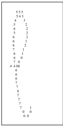
An example of an image of character “e”, the same character used in Fig. 3 and Fig. 7, is shown in Fig. 13, after it has been chain coded. From the chain codes of the character, features such as the type of strokes will be extracted. The strokes will be identified with a set of probabilities. HMM is used for this purpose [22]. How these features are extracted by means of HMM and later used by a fuzzy inference system for classification is the other novelty of this research work. Elaboration of these phases are given in [22][23]. In this paper only the methods prior to these stages are described.
Figure 13. An image of chain-coded “e”
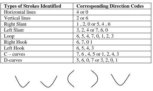
After a careful study of the different types of stroke directions in a character set, a few types are selected and thought to have distinguishing factors to identify a character class. Table II shows the types of strokes that are used to distinguish the characters. In order to simplify the stroke without needing to consider the way it might be traversed, codes that visually produce the same, the directions are usually combined. For example, in identifying a vertical stroke, if the image is traversed from bottom up, then the direction will be North and if it is traversed top to bottom the direction will be South. Of course the traversing method is meant to be consistent and it will always traverse the same way, but just in case, the directions are disregarded and both will be considered as a vertical stroke. Hence are true for the horizontal stroke, the right slant and the left slant.
The other two obvious strokes are named as the C-curve and the D-curve. The last two strokes will be given the highest priorities in the investigation of strokes. In the case where the curve might be broken or not very distinguishable, then the normal NSEW directions will be investigated. The combination of these smaller identifiable strokes can still make a good set of features for producing linguistic variables. The C-curve would be a prominent feature in characters like a, c, d, e etc., and the D-curve in characters like b, p, etc. Some of the characters may have the combinations of both curves and some may have a fuller curve than others. All these differences are projected in the linguistics that will describe the strokes. The codes that form the strokes and the visual examples of some of the strokes investigated are shown in Table II and Fig. 14.
5 5 5 5 4 3
4 3
5 2
6 2
5 2
6 2
6 1
6 2
7 1
6 1
6 0
7 0 4 4 06 6
6
6
7
7
6
7
7
7
7 1
0 0 0 0
While there are still edges to be traversed Begin
Find the starting point to traverse.
From starting point till junction point or end point Begin
Find and store the direction code of the point by investigating its neighbour position.
Once done, clear pixel from image. End
TABLE II. AMONG THE TYPES OF STROKES IDENTIFIED FROM THE CHARACTER IMAGE.
Types of Strokes Identified Corresponding Direction Codes Horizontal lines 4 or 0
Vertical lines 2 or 6
Right Slant 1 , 2, 0 or 5, 4 , 6 Left Slant 3, 2, 4 or 7, 6, 0
Loop 6, 5, 4, 7, 0, 1, 2, 3
Right Hook 6, 7, 0 1
Left Hook 6, 5, 4, 3
C – curves 7, 6 , 4, 5 or 1, 2, 4, 3 D-curves 5, 6, 0, 7 or 3, 2, 0, 1
Figure 14. Visual examples of some of the strokes identified (from left to right : right hook, left hook, C-curve, D-curve, U-curve).
VI. CLASSIFICATIONPHASE
A brief mention of the classification phase would be required to give a more meaningful account of the work mentioned in this paper. The classification phase of the system is based on the concept of fuzzy rules developed using Mathlab (Version 7.4.0). The fuzzy inference system (FIS) was built using Mathlab GUI tools from its Fuzzy Logic Toolbox.
A fuzzy rule has two components, an if-part (referred as the antecedent) and a then-part (referred to as the consequent). The structure of a fuzzy rule is identical to that of a conventional rule in artificial intelligence. The main difference is the antecedent of a fuzzy rule is described by a linguistic variable and a membership function. A linguistic variable is like a composition of a symbolic variable and a numeric variable. Numeric variables are frequently used in science, engineering, mathematics, medicine and many other disciplines, while symbolic variables play an important role in AI and decision sciences. Using the notion of the linguistic variable to combine these two kinds of variables into a uniform framework is one of the main reasons that fuzzy logic has been successful in offering intelligent approaches in engineering and many other areas that deal with continuous problem domains.
A HMM model is a very useful tool to be incorporated into a fuzzy logic rule based system. It provides an approach that is compatible to the needs of the system. The calculation of probabilities by a statistical model such as HMM provides a solid base for the more syntactical approach of a fuzzy system. HMM yields a more accurate assessment of probabilities for the linguistic variables of a fuzzy system. In the following sub-sections a very brief account of the subsequent components of the whole research work is given.
A. HMM Models of the strokes
Each of the strokes has its own HMM model. The HMM models for the strokes have varied numbers of states from N = 3 to N = 9. Strokes that need lesser codes to be identified would have lesser states, and strokes with more codes to be identified benefit from having more states. The observation symbol, M, is 8, as the direction codes are from 0,..,7. K = 7 to 10, which is the train sample set used to train each of the HMM models.
The HMM model used for all the strokes are the left-right model. The fundamental property of all left-left-right HMM is that no transitions are allowed to states whose indices are lower than the current state, and the initial state probabilities have the property , πi = 0, if i ≠ 1, πi = 1, if i = 1, since the state sequence must begin in state 1 and end in state N. The model also allows jumps of no more than one. B. Fuzzy Logic Classifier
The features extracted by the HMM yield a very good medium for further conversion of the linguistic variables. The strokes as identified, together with their probabilities will go through the process of fuzzification. The triangular and the trapezoidal membership functions were used to change the probabilities into their linguistic variable forms. The two membership functions were chosen due to their simple formulas and computational efficiencies. Examples of the linguistic variables used are : “very tall right slant”, “very tall vertical line”, as in l’s, or as in some of d’s or b’s. “Tall C-curve” as in c’s, “small C-curve” as appear in d’s, a’s and so on. When the HMM models were used with the fuzzy rules to recognize the handwritten characters, a favorable result was achieved.
VII. DISCUSSIONS
This paper presented detailed descriptions of each pre-processing step. The objective was to share the experiences and methods in implementing the steps. Though there are many readily available pre-processing tools that can be used to clean, binarise and thin the image, the later process like chain-coding is not readily available, for example in a Mathlab toolkit. In order to chain-code the image, an understanding of the image data file would be advantageous. Furthermore, self-coding the pre-processing phase would also give the flexibility of tailoring the process to the exact requirements of each subsequent phase.
ACKNOWLEDGMENT
This research work is part of a PhD research project that is sponsored by Universiti Tenaga Nasional.
REFERENCES
electronic Journal of Computer Science and Information Technology (eJCSIT), Vol. 2, No. 1, 2010
A. Suliman, M. N. Sulaiman, M. Othman and R. Wirza, Chain Coding and Pre Processing Stages of Handwritten Character Image File 13 [2] Arica, N., and Yarman-Vural. F.T., “An Overview of Character
Recognition Focused on Off-line Handwriting”, IEEE Trans. On Systems, Man, and Cybernetics, Vol. 31. No. 2, 2001, pp. 216-233. [3] Serra, J., “Morphological Filtering : An Overview”, SignalProcess,
vol. 38, no. 1, 1994, pp. 3-11.
[4] Sonka, M., Hlavac V. and Boyle, R., Image Processing, Analysis and Machine Vision, 2nd ed. Pacific Grove CA:Brooks/Cole, 1999. [5] Legault R. and Suen C.Y., “Optimal local weighted averaging
methods in contour smoothing”, IEEE Trans. Pattern Anal. Machine Intell., vol.18, pp. 690-706, July, 1997.
[6] Leu, J.G., “Edge Sharpening through ramp width reduction”, Image Vis. Comput., vol. 18, no. 6-7, 2000, pp. 501-514.
[7] Solihin, Y. and Leedham C.G., , “Integral ratio: A new class of global thresholding techniques for handwriting images”, IEEE Trans. Pattern Anal. Machine Intell., vol.21, August,1999, pp. 761-768.
[8] Lee, W.L. and Fan, K.C., “Document image preprocessing based on optimal Boolean filters”, Signal Process, vol.80, no. 1, 2000, pp. 45-55.
[9] Polesel, A., Ramponi, G., and Mathews, V., “Adaptive unsharp masking for contrast enhancements”, in Proc. Int. Conf. Image Process., vol. 1, 1997, pp.267-271.
[10] Atici, A. and Yarman-Vural, F., “A Heuristic Method for Arabic Character Recognition”, Signal Process, vol. 62, 2001, pp. 87-99. [11] Chen, M.Y., Kundu, A. and Zhou, J., Off-Line Handwritten Word
Recognition using HMM type Stochastic Network, IEEE Transactions of Pattern Analysis and Machine Intelligence, 16, 1994, 481-496.
[12] Reinhardt, J.M. and Higgins, W.E., 1996, Comparison between the morphological skeleton and morphological shape decomposition, IEEE Trans. Pattern Anal. Machine Intell., vol. 18, pp. 951-957, Sept. [13] Yang, J. and Li, X.B., 1995, Boundary Detection using mathematical morphology, Pattern Recognition Letters, vol. 16, no.12, pp. 1287-1296.
[14] Saula, J. and Pietikainen, M., “Adaptive document image binarization”, Pattern Recognit., vol. 33, no. 2, 2000, pp. 225-236. [15] Bozinovic, R.M., and Srihari, S.N., “Off-Line Cursive Script Word
Recognition”, PAM1, 1989, 11 68-83.
[16] Suen, C.Y., 1986, Character Recognition by Computer and Applications in Handbook of Pattern Recognition and Image Processing, ed. Young T.Y., Fu, K.S., Academic Press Inc., San Diego, CA, pp. 569-586.
[17] Impedovo, S., Ottaviano, L. and Occhinegro, S., 1991, Optical Character Recognition – A Survey, International Journal of Pattern Recognition & Artificial Intelligence, 5, 1-24.
[18] Oh, I.S., Lee, J.S. and Suen, C.Y., 1999, Analysis of class separation and combination of class-dependent features for handwriting recognition, IEEE Trans. Pattern Anal. Machine Intell., vol. 21, pp.1089-1094, October.
[19] Blumstein, M. and Verma, B., 1999, A new segementation algorithm for handwritten word recognition, Proc. of the Int. Joint Conf. on NN, IJCNN ’99, Washington D.C., 878-882.
[20] Madhvanath, S. and Govindaraju, V., 1999, References lines for holistic recognition of handwritten words, Pattern Recognition, vol. 32, no.12, 2021-2028.
[21] Madhvanath, S., Kim, G. and Govindaraju, V., 1999, Chaincode contour processing for handwritten word recognition, IEEE Pattern Anal Machine Intell. , vol. 21, 928-932, September.
[22] Suliman, A., Sulaiman, M.N., Othman, M., and Wirza, R., Extracting Features for the Linguistic Variables of Fuzzy Rules Using Hidden Markov Model, International E- Conference on Computer Science (IeCCS), 9 – 11 July 2007, Greece, AIP Conference Proceedings. [23] Hybrid Approach of HMM and Fuzzy Logic of Handwriting