AN UTILITY FRIENDLY DIRECT
TORQUE CONTROL TECHNIQUE OF
THREE PHASE INDUCTION MOTOR
WITH TWO LEVEL INVERTER USING
180 DEGREE CONDUCTION MODE.
Mr.Manoj Kumar Sahu1 Dr.B.P.Panigrahi2 Dr.A.K. Panda3
Manoj Kumar Sahu,
Associate Professor and HOD in Dept. of EEE, Hi-Tech college of Engg., Bhubaneswar, BPUT ,Orissa
Dr. B.P. Panigrahi ,
Professor and HOD in Dept. of EE, IGIT Sarang, BPUT, Orissa
Dr. A.K. Panda,
Professor in Dept. of EE, NIT Rourkela, Orissa
Abstract:
The vector control is still very complex to implement. As a consequence of the perseverant efforts of various research engineers, an improvised scalar method known as Direct Torque Control (DTC) was invented. This method considerably alleviates the computational burden on the control platform while giving a performance which is comparable to that of a vector controlled drive. In this paper, the DTC scheme employing a Voltage Source Inverter (VSI) is possible to control directly the stator flux linkage and the electromagnetic torque by the optimum selection of inverter switching vectors. The selection of inverter switching vector is made to restrict the flux and torque errors within the respective flux and torque hysteresis bands. This achieves a fast torque response, low inverter switching frequency and low harmonic losses. The proposed scheme is described clearly and simulation results are reported to demonstrate its effectiveness. The entire control scheme is implemented with Matlab/Simulink.
Keywords: Direct torque control; induction motor drives; two-level inverter
1. Introduction
The application of the field oriented control method for variable speed induction motor drives leads to a complex control system structure. Generally, a closed loop field oriented control system consists of the following components:
(1)PID controller for motor flux and torque, (2) current and/or voltage decoupling network, (3) complex coordinate transformation, (4) two axis to three axis converter, (5) voltage or current modulator, (6) flux and torque estimator, (7) PID (sliding mode) speed controller
does not have the same relationship. This reduces the dependence of the schemes on many motor parameters, thus making it a robust scheme in the flux-weakening region [6]. The flux and torque are controlled by using the position of the flux phasor. The implementation of this scheme requires flux linkage and torque computations, plus generation of switching states through a feedback control of the torque and flux directly without inner current loops [7-8]. The voltage source inverter has eight switching states (six active and two zero states), which is obtained according 1800 conduction mode [9].
2. Torque Expressions with Stator and Rotor Fluxes
The torque expression for induction machine can be expressed in vector form as,
2
2
3
s s eI
P
T
ψ
=
(1) Whereψ
s=
ψ
qss−
j
ψ
dss and dsss qs s
i
ji
I
=
−
. In this equation,I
s is to be replaced by rotor fluxψ
r .In the complex form,
ψ
s andψ
r can be expressed as function of currents as,r m s s
s
=
L
I
+
L
I
ψ
(2)s m r r
r
=
L
I
+
L
I
ψ
(3)Eliminating
I
r from equation (2), we get' s s r r m
s
L
I
L
L
+
=
ψ
ψ
(4)where
L
's=
L
sL
r−
L
m2. The corresponding expression ofI
s is1
' ' r s r m s s sL
L
L
L
I
=
ψ
−
ψ
(5)Substituting equation (5) in (1)and simplifying yields
s r s r m e
L
L
L
P
T
'ψ
ψ
2
2
3
=
(6)That is, the magnitude torque is
sin
2
2
3
'
ψ
rψ
sγ
s r m eL
L
L
P
T
=
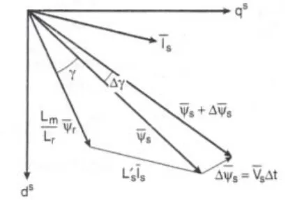
(7)Figure 1:Stator flux, rotor flux, and stator current vectors on ds-qsplane
(Stator resistance neglected)
where γ is the angle between the fluxes. Figure 1 shows the phasor (or vector) diagram for equation (6), indicating the vectors
ψ
s ,ψ
r , andI
s for positive developed torque. If the rotor flux remains constant and stator flux is changed incrementally by stator voltageV
s as shown and the corresponding change of γ angle isΔ
γ
, the incremental torqueΔ
T
e expression is given assin
2
2
3
'ψ
ψ
+
Δ
ψ
Δ
γ
=
Δ
r s ss r m e
L
L
L
P
T
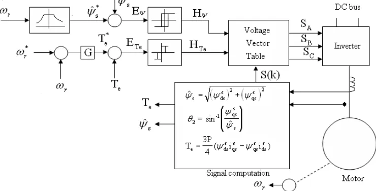
( 8)3. Control Strategy of DTC
The block diagram of direct torque and flux control is shown in Figure 2 and Figure 3 explains the control strategy. The command stator flux
ψ
ˆ
s*and torque*
e
T
magnitudes are compared with the respective estimated values and the errors are processed through hysteresis-band controllers, as shown. The flux loop controller has two levels of digital output according to the following relations:for
1
ψ ψ
ψ
E
HB
H
=
>
+
(9)ψ ψ
ψ
E
HB
H
=
−
1
for
<
−
(10) Where2
HB
ψ = total hysteresis-band width controller. The circular trajectory of the commandflux vector
*
ˆ
sψ
with the hysteresis band rotates in an anti-clockwise direction as shown in Figure 3(a). The actual stator fluxψ
s is constrained within the hysteresis band and it tracks the command flux in a zigzag path.The torque control loop has three levels of digital output, which have the following relations:
Te Te
Te
E
HB
H
=
1
for
>
+
(11)Te Te
Te
E
HB
H
=
−
1
for
<
−
(12)for
0
Te Te Te
Te
HB
E
HB
The feedback flux and torque are calculated from the machine terminal voltages and currents. The signal computation block also calculates the sector number S(k) in which the flux vector
ψ
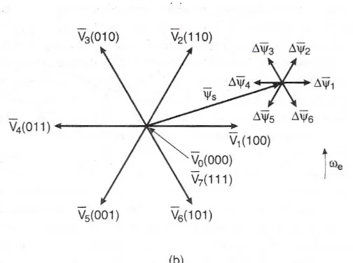
slies. There are six sectors each π/3 angle wide), as in Figure 3(a).Figure 3: (a) Trajectory of stator flux vector in DTC control, (b) Inverter voltage vectors and corresponding stator flux variation in time Δt.
The voltage vector table block in Figure 2 receives the input signals
H
ψ,
H
Te,
and S(k) and generates the appropriate control voltage vector (switching states) for the inverter by lookup table, which is shown in table 1(the vector sign is deleted). The inverter voltage vector (six active and two zero states) and a typicalψ
s areshown in Figure 3(b). Neglecting the stator resistance of the machine, we can write
)
(
ss
dt
d
V
=
ψ
(14) or.
t
V
s s=
Δ
Δ
ψ
(15)Which means that
ψ
s can be changed incrementally by applying stator voltageV
s for time increment Δt. Theflux increment vector corresponding to each of six inverter voltage vectors is shown in Figure 3(b). The flux in machine is initially established to at zero frequency (dc) along the trajectory aA shown in Figure 3(a). With the rated flux, the command torque is applied and the
ψ
s*vector starts rotating. Table 1 applies the selectedvoltage vector, which essentially affects both the torque and flux simultaneously. The flux trajectory segments AB, BC, CD and DE by the respective voltage vectors
V
3,
V
4,
V
3,
and
V
4 are shown in Figure 3(a). The total and incremental torque due toΔ
ψ
s are explained in figure 1. Note that the stator flux vector changes quickly by, but theψ
r change is very sluggish due to large time constant Tr. Sinceψ
r is more filtered, itmoves uniformly at frequency ωe, whereas
ψ
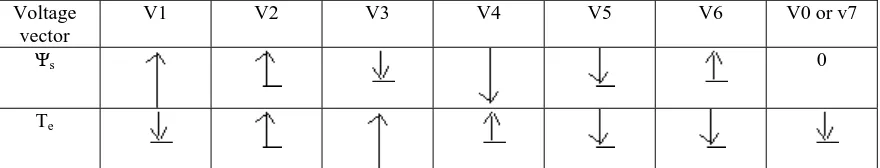
s movement is jerky. The average speed of both, however, remains the same in the steady-state condition. Table 2 summarizes the flux and torque change (magnitude and direction) for applying the voltage vectors for the location ofψ
s shown in Figure 3(b). The flux can be increased by theV
1,
V
2,
and
V
6 vectors (vector sign is deleted), whereas it can be decreased by the5 4
3
,
V
,
and
V
1
1 V2 V3 V4 V5 V6 V1 0 V0 V7 V0 V7 V0 V7 -1 V6 V1 V2 V3 V4 V5
-1
1 V3 V4 V5 V6 V1 V2 0 V7 V0 V7 V0 V7 V0 -1 V5 V6 V1 V2 V3 V4
Table 1: Switching table of inverter voltage vectors Voltage
vector
V1 V2 V3 V4 V5 V6 V0 or v7
Ψs 0
Te
Table 2: Flux and Torque variations due to applied voltage vector in Figure 3.(b) (Arrow indicates magnitude and direction)
Similarly, torque is increased by the
V
2,
V
3,
and
V
4 Vectors, but decreased by the6 5
1
,
V
,
and
V
V
vectors. The zero vectors (V0 or V7) short-circuit the machine terminals and keeps the flux and torque unaltered. Due to finite resistance (Rs) drop, the torque and flux will slightly decrease during the short-circuit condition. Consider for example, an operation in sector S (2) as shown in Figure 3(a), where at point B, the flux is too high and the torque is too low; that is,H
ψ=
−
1
andH
Te=
+
1
. From table 1, voltage V4 is applied to the inverter, which will generate the trajectory BC. At point C,H
ψ=
+
1
and1
+
=
TeH
and this will generate the V3 vector from the table. The drive can easily operate in the four quadrants, and speed loop and field-weakening control can be added, if desired. The torque response of the drive is claimed to be comparable with that of a vector-controlled drive.4. Design Example
Power 1 hp Voltage (L-L) 415 V Stator Resistance 6.03 ohm Rotor resistance 6.085 ohm Stator inductance 489.3e-3 H Rotor Inductance 489.3e-3 H Mutual Inductance 450.3e-3 H Number of Poles 4
Moment of Inertia 0.00488 kg.m2 Dc link voltage 2*190 V Reference Speed 157 rad/sec. Proportional Constant 5.
Integrator Constant 0.75.
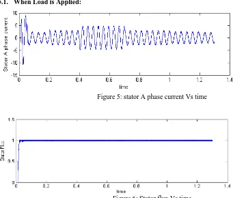
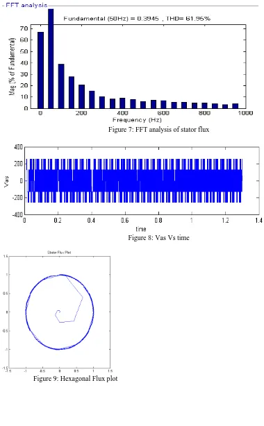
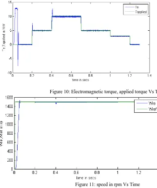
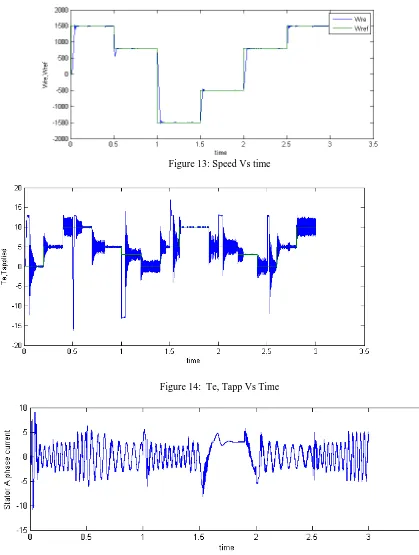
5. Simulation Results
diagram of dtc method for three phase induction motor. Simulation wave form of stator A phase current , stator flux and FFT analysis of stator flux is shown in fig.(5), fig.(6) and fig.(7) respectively .Simulation of stator phase-A voltage and stator d-q axis flux locus is shown in fig.(8) and fig.(9).Simulation of torque and speed is shown in fig.(10) and fig.(11).Similarly when speed is reversed output characteristics of induction motor is shown in fig.(12), fig.(13) ,fig.(14) and fig.(15).
Figure 4: Simulation diagram of direct torque control method of three phase induction motor
5.1. When Load is Applied:
Figure 5: stator A phase current Vs time
Figure 7: FFT analysis of stator flux
Figure 8: Vas Vs time
Figure 9: Hexagonal Flux plot
Figure 10: Electromagnetic torque, applied torque Vs Time
Figure 11: speed in rpm Vs Time
5.2. When Speed is Reversed:
Figure 13: Speed Vs time
Figure 14: Te, Tapp Vs Time
Figure 15: Stator A phase current Vs time
6. Result Discussion and Conclusion
transformation required as in vector control. But hysteresis-band control generates flux and torque ripple, which can be reduced by using multilevel inverter having space vector pulse width modulation.
References
[1] I. Takahashi, S. Asakawa, "Ultra-Wide Speed Control of an Induction Motor Covered 10A6Range", IEEETransactions on Industry Applications, IA25, pp. 227-232, 1987
[2] M. Depenbrock, “Direct Self control (DSC) of inverter fed induction motor drive, “Trans. On IEEE-Power Electronics, vol. 3, no. 4, pp. 420-429, Oct.1988.
[3] I. Takahashi, T. Nogushi, "ANew Quick-Response and High-Efficiency Control Strategy of an Induction Motor", IEEE Trans. Industry Applications, Vol. IA-22, pp. 820-827, October 1986.
[4] D.Casadei, G.Grandi, G.Serra, and A.Tani, “Effects of flux and torque hysteresis band amplitude in direct torque control of induction machines”, Proc. of IECON ’94, pp. 299-304.
[5] D.Casadei, GSerra, and A.Tani, “Constant frequency operation of a DTC induction motor drive for electnc vehicle”, Cod. Proc. of ICEM ‘96, Vol. IU, pp. 224-229.
[6] J. KANG, S SUL, "New Direct Torque Control of Induction Motor for Minimum Torque Ripple and Constant Switching Frequency". IEEE Trans. on Industry Applications, Vol. 35, No. 5; September 1999, pp 1076 – 1082.
[7] G. S. Buja and M. P. Kazmierkowski “Direct Torque Control of PWM Inverter-Fed AC Motors-A survey”. IEEE Trans. on Industrial Electronics vol. 51, num. 4 pp. 744-758, August 2004.