PERFORMANCE COMPARISON OF
DIFFERENT LED DRIVER
Ramjee Prasad Gupta
Department of Electrical Engineering B.I.T., Sindri, Dhanbad ,Jharkhand
Dr. Upendra Prasad
Department of Electrical Engineering B.I.T., Sindri, Dhanbad ,Jharkhand
ABSTRACT:
Because of its inherent characteristics like vibration resistant, energy saving, less pollution, with better luminous efficiency, Light Emitting Diode (LED) application is constantly expanding, in particular, in the area of lighting. As the power of a single LED is very small, but in lighting, the uniform flux and illuminance in a certain region are required, so it is necessary to use LEDs in array for increasing the brightness and luminous area and improving the uniformity of illuminance. For this it is necessary to drive LED suitably. Now a days because of improved features LED based Cap-Lamp are suggested instead of incandescent based Cap-Lamp for miner’s in case of underground coalmines. In this paper different ways to operate LED has been discussed and emphasis has been focussed to drive LED with constant current for uniform illuminance.
KEYWORDS : LED, Pulse Width Modulation (PWM),driver circuit
INTRODUCTION :
Basically, LEDs are current-driven devices whose brightness is proportional to their forward current. Forward current can be controlled in two ways. The first method is to use the LED V-I curve to determine what voltage needs to be applied to the LED to generate the desired forward current. This is typically accomplished by applying a voltage source and using a ballast resistor as shown in figure 1. However, this method has several drawbacks. Any change in LED forward voltage creates a change in LED current. As voltage and currents are not related linearly so with a nominal forward voltage of 3.55 V, the LED as shown in Figure 1 has 22 mA of current. If this voltage changes to 4.1 V, which is within the specified voltage tolerance due to temperature or manufacturing changes, the forward current drops to 13 mA. This 15% change in forward voltage causes a much larger 40% change in forward current. Also, depending upon the available input voltage, the voltage drop and power dissipation across the ballast resistor results in wasting of power and finally, reduce the battery life. The second, preferred method of regulating LED current is to drive the LED with a constant-current source. The constant-current source eliminates changes in current due to variations in forward voltage, which translates into a constant LED brightness. Generating a constant-current source is relatively simple. Rather than regulating the output voltage, the input power supply regulates the voltage across a current-sense resistor. Figure 2 shows this implementation. The power-supply reference voltage and the value of the current-sense resistor determine the LED current. Multiple LEDs should be connected in a series configuration to keep an identical current flowing in each LED. Driving LEDs in parallel requires a ballast resistor in each LED string, which leads to lower efficiency and uneven current matching. The brightness of LEDs is directly related to their current. An effective way to ensure that each LED produces similar light output is to connect them in series. However, a major drawback of a series connection of LEDs is their cumulative voltage drop that eventually limits the number of LEDs in a string. On the other hand, simple paralleling of LEDs or LED strings is not desirable because of current sharing problems related to the LED’s exponential voltage-current characteristic with a negative temperature coefficient of the forward-voltage [1]. There are several methods of driving multiple LED strings connected in parallel. A straightforward approach is to employ a current regulator for each string, as shown in Fig. 2. Generally, the current regulator can be of linear or switch mode type. The approach employing linear regulators offers a low cost, but suffers from a poor operating efficiency because the voltage drop across the linear regulator, i.e., the voltage difference between the input and output voltage of the linear regulator, cannot be minimized under all operating conditions. Namely, the input voltage of the linear current regulators needs to be set based on the worst-case condition, i.e., for the maximum LED string voltage
pre-regulator is automatically adjusted to keep the minimum linear-regulator voltage to Vmin = Vref – Vf, where Vf is the forward voltage drop of the sensing diodes. The efficiency performance of this approach is strongly affected by the selection of reference voltage Vref and characteristics of the sensing diodes, primarily their temperature dependence. Because of the tolerances of minimum voltage drops of linear current regulators, i.e., tolerances of dropout voltages, reference voltage Vref must be selected above the anticipated worst-case voltage, which is the highest dropout voltage expected. As a result of an increased reference voltage required to provide the worst-case design margin, the efficiency of the driver in Fig.4 is always lower than the possible maximum efficiency. Moreover, because of the strong temperature dependence of the forward voltage of the sensing diodes, the actual sensed minimum voltage drop across the linear regulators varies with the operating temperature causing a significant variation of the power loss. The detrimental effects of the non-optimal reference voltage Vref and temperature dependence of the forward voltage drop of the sensing diodes are progressively more pronounced as the number of LEDs in a string decreases.
For some sophisticated application like underground coalmines the lighting system should be free from any flickering. Hence PWM control becomes the better choice for LED based lighting system
.
LED Driving Methodology :
By using active and passive elements circuits are designed to drive the LED emitter array at a constant voltage or constant current despite input voltage or load variations[9]. These circuits are called voltage or current regulator circuits because they are designed to regulate the input voltage to generate either a fixed output voltage or current. The use of voltage or current regulation improves the operation of the LED based lamp. Since the drive current of the LED array remains constant despite variations in the supply voltage, the light output is not affected by input voltage variations. Since the drive current doesn’t increase due to over voltage conditions, the LED emitters can be driven at a higher forward current at the design voltage without exceeding the maximum allowable forward current at the maximum input voltage. In addition, if the circuit is located outside of the LED based lamp , the voltage or current regulator circuit can improve the thermal properties of the signal lamp by reducing the power consumption within the LED based lamp. Block diagrams of typical voltage and current regulator circuits are shown in figure 7-12. The basic elements of all of these circuits consist of a high gain amplifier and feedback circuit, which vary the dynamic load of a power circuit that is either in series or parallel with the LED emitter array. The regulator circuit modulates the dynamic load so as to provide either a constant voltage or current to the LED emitter array independent of input voltage or load variations (over some specified range). Voltage regulator circuits measure the voltage across the load and compare the load voltage with a reference voltage. Current regulator circuits usually measure the current through the load by measuring the voltage drop across a sense resistor in series with the load. Then the voltage across the sense resistor is compared with a reference voltage. Since most LED based lamp designs consist of several LEDs emitters, they are normally arranged in one or more series-connected strings, such as shown in figure 7-12. While it is possible to use one voltage or current regulator per string, but by using a single voltage or current regulator for the entire LEDs array driver circuit can be designed reducing overall cost. Since LED emitters are current-controlled devices, voltage regulator circuits should use current limiting resistors in series with each string of LED emitters (figure 7 ), paralleled string of LED emitters (figure 8 ), or cross-connected paralleled string of LED emitters (figure 9).
longer regulate the output voltage or current. Thus, for proper voltage or current regulation, the input voltage needs to be higher than the sum of the drop-out voltage, the voltage across the load, and the voltage drop across the sense resistor if employed. The circuits shown in figure 9 and figure 12 are called switching regulators. They use a dynamic load that is switched ON and OFF at very high frequencies at a varying duty cycle. The dynamic load supplies electrical power to an energy storage element such as a capacitor or an inductor or a combination of both. This energy storage element then supplies power to the load. The percentage of time the dynamic load is ON is varied depending on the input voltage and load requirements. The switching. regulator provides the highest power efficiency of the three circuits. However, it is the most complex of the three regulator circuits and has the highest potential for creating unwanted EMI (due to the high-frequency switching). Finally, The LEDs array can be driven from either a voltage regulator or a current regulator circuit. With a current regulator, the total array current will be independent of supply voltage, temperature and forward voltage category variations as long as the current regulator remains in its active region. If the current regulator is used with parallel-connected LED emitters, such as shown in figure 8 or figure 9, there can still be similar forward current variations within the LEDs array. Note that the forward current matching can be improved with the addition of a small resistor in series with each string for the circuit shown in figure 8. With a voltage regulator, the forward voltage applied to the LED array voltage will be independent of supply voltage variations as long as the voltage regulator remains in its active region. However, ambient temperature variations and the use of different forward voltage categories can affect the forward current through the LED array unless provisions are made in the design. If the driver circuit uses a voltage regulator with a fixed output voltage, then the values of these current-limiting resistors will need to be varied for each of the different forward voltage categories in order to compensate for the different forward voltages at the design current. Alternatively, we can use the same value of current-limiting resistors for all forward voltage categories. However, in this case, the regulator output voltage would need to be varied slightly for each different forward voltage category to compensate for the different forward voltages at the design current. Despite these precautions, there will still be small variations in the total current through the LED array due to slightly different forward voltages of the individual emitters. With only a small voltage drop across the current limiting resistor, small variations in the regulated voltage can cause large changes in forward current through the LED emitters. In addition, since the forward voltage of the LED emitter varies with temperature, the forward current through the LED array will increase at elevated temperatures. However, it is possible to maintain fixed current through the LEDs array.
RESULT DISCUSSION:
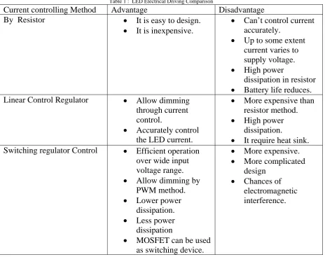
With the help of figure 13. a constant current LED driver can be designed. Table1 shows the comparison between different current controlling scheme.
control.
Accurately control
the LED current.
High power
dissipation.
It require heat sink.
Switching regulator Control
Efficient operation
over wide input
voltage range.
Allow dimming by
PWM method.
Lower power
dissipation.
Less power
dissipation
MOSFET can be used
as switching device.
More expensive.
More complicated
design
Chances of
electromagnetic
interference.
Different key parameters for driver circuit are as follow : 1. Vsense= 0.7 V at Tj= 27 ºC.
2. PD ie, power dissipation for internal circuitry is 0.055W at 12V input and 0.25W at 24V input.
3. Maximum power dissipation is assumed as 1.13W.
4. It supplies constant LED current for varying input voltage up to 28V max 5. Output current level is defined by the resistor R.
6.LED current required, I LED is 0.5A
7. Resistor value for R = Vsense / ILED = 0.7V/0.5 Ohm = 1.4 Ohm.
Heat dissipation Calculation :
For an Array of 4 LEDs the minimum forward Voltage Vfmin =1.9Vand typical forward voltage Vftyp= 2.2V is considered. The power dissipation in the current regulator should be calculated for Vfmin, where the voltage drop across the current driver would be maximum. This will prevent the driver circuit from overheating.
Vfmin = 1.9V Vftyp = 2.2V
Total voltage across LED, VLED = 1.9V x 4 = 7.6V at Vfmin and VLED = 2.2V x 4 = 8.8V at Vftyp. Voltage drop ,Vdrop = Vin – Vsense- VLED = 12V – 0.7V -7.6V = 3.7V at Vfmin and
Vdrop = 12V -0.7V – 8.8V = 2.5V at Vftyp. Power dissipation :
CONCLUSION:
For a typical application like underground coalmines LED based lighting system will provide a better choice for miner’s. But to ensure good long-term reliability and brightness uniformity, the LED shall be driven by constant current source. The VI curve for LED is similar to the VI curve for normal diode, except that it has steeper slope of If versus Vf in the high current region. Hence, with the variation of 0.1V in the supply voltage will cause the forward current differs by approximately 60mA. Since the luminous intensity of LED varies with forward current, this causes the relative intensity to vary by >15%. Therefore, LED circuitry should be designed to drive by controlled current source rather than controlled voltage source. Linear LED driver are less efficient and generally occupy a larger space. Switch mode LED driver is more efficient and generally smaller. However, they have electrical and radiated noise and are complicated to design. When the input power supply is lower than the LEDs total VF, switch mode LED driver must be used. In switch mode LED driver the size of battery also reduces. The selection between linear or switch mode is generally decided by simplicity, the available power supply and efficiency. The switch mode LED driver is related to the switching voltage regulator topologies. The switching voltage regulator maintains a constant voltage at various current loads. The switch mode LED driver however, deliver constant current to LED at whatever Vf the LEDs required, provided that the over voltage protection or power rating is not exceeded.
REFERENCES :
[1] G. Carraro, “Solving high-voltage off-line HB-LED constant current control-circuit issues,” IEEE Applied Power Electronics Conference (APEC) Proc., pp. 1316 - 1318, 2007.
[2] H. Broeck, G. Sauerlander, and M. Vendt, “Power driver topologies and control schemes for LEDs,” IEEE Applied Power Electronics Conference (APEC) Proc., pp. 1319 - 1325, 2007.
[3] T. F. Pan, H. J. Chiu, S. J. Cheng, and S. Y. Chyng, “An improved single-stage Flyback PFC converter for high luminance lighting LED lamps,” The 8th International Conference on Electronic Measurement and Instruments, Vol. 4, pp. 212 - 215. Aug. 2007.
[4] H. J. Chiu and S. J. Cheng, “LED backlight driving system for large-scale LCD panels,” IEEE Transactions on Industrial Electronics, Vol. 54, No. 5, pp. 2751 - 2760, Oct. 2007.
[5] G. Spiazzi, S. Buso and G. Meneghesso, “Analysis of a highpower-factor electronic ballast for high brightness light emitting diodes,” IEEE Power Electronics Specialists Conference (PESC) Proc., pp. 1494 - 1499, 11 - 14 Sept. 2005.
[6] Y. H. Fan et al, “A simplified LED converter design and implement,” The 9th Joint Conference on Information Sciences (JCIS), Taiwan, Oct. 8 - 11, 2006.
[7] L. Burgyan and F. Prinz, “High efficiency LED driver,” United States Patent 6690146, Feb. 10, 2004.
[8] M. Doshi and R. Zane, “Digital architecture for driving large LED arrays with dynamic bus voltage regulation and phase shifted PWM,” IEEE Applied Power Electronics Conference (APEC) Proc., pp. 287 - 293, 2007.
[9] www.lumileds.com