Use of in-
fi
lled trenches to
screen ground vibration due to
impact pile driving:
experimental and numerical
study
Pubudu Jayawardanaa,∗, R. Achuhanb, G. H. M. J. Subashi De Silvab, D. P. Thambiratnama
aSchool of Civil Engineering and Built Environment, Science and Engineering Faculty, Queensland University of Technology, Brisbane, Australia
bDepartment of Civil and Environmental Engineering, Faculty of Engineering, University of Ruhuna, Galle, Sri Lanka
∗Corresponding author.
E-mail address:[email protected](P. Jayawardana).
Abstract
Vibration generated by pile driving can cause discomfort to occupants of nearby buildings and disturb the activities carried out in the buildings. The transmitted vibration will depend on both the source and the transmitting medium (soil), while the acceptable levels of vibration will depend on the receiver characteristics. Existing structures in which some sensitive processes are ongoing such as hospitals and laboratories can easily be affected due to the received vibration. Introducing a trench into the path of wave propagation has become one of the solutions. There is however little experimental data available on the effects of trenches to screen such ground borne vibration, especially that caused by pile driving. This paper describes a series of experiments conducted to investigate the characteristics of impact pile induced vibrations and the effect of coal bottom ash filled trenches to screen this vibration. In addition to experimental testing, numerical simulations are also carried out using validated model to examine the effects of in-fill material, impact load, soil characteristics
15 February 2018 Revised: 15 June 2018 Accepted: 2 August 2018
Cite as: Pubudu Jayawardana, R. Achuhan,
G. H. M. J. Subashi De Silva, D. P. Thambiratnam.Use of in-filled trenches to screen ground vibration due to impact pile driving: experimental and numerical study.
Heliyon 4 (2018) e00726.
and distance from the source to the trench on the vibration screening ability. The results of the field experiments and the numerical study are analysed and interpreted to provide guidelines for future research and design.
Keyword: Civil engineering
1. Introduction
Ground vibration from piling is inevitable during infrastructure developments in ur-ban cities. In order to maximize the land usage, tall and heavy supper structures are being constructed in urban cities in the vicinity of inhabitants and users of buildings. These building structures are mostly founded in soft soils and often supported by groups of piles. Relatively high ground vibration is induced by piling compared with the other source of vibration. Velocity magnitudes of the ground vibration from piling can vary from mild (0.7 mm/s for press-in piles), moderate (8.3 mm/s for vibratory piles) to severe (15.2 mm/s for impact piling by a diesel hammer)
[1]. Once these vibration waves are generated, they are easily transferred through the soil media and eventually reach structures and cause discomfort to the occupants, disturb the activities carried out in the buildings (such as laboratory testing or oper-ations in a hospital) and at times cause damage to the structure. Vibroper-ations which originate from the impact piling (or pile driving) are difficult to determine and costly to mitigate. In response, regulatory authorities are compelled to impose restrictions on the use of impact pilling or to use alternative foundation methods since there is a lack of knowledge to assess the risk of vibration caused by pile driving[2]. Impact pile driving involves dropping a large mass from a particular height on top of a precast pile. The generated energy penetrates the pile into the soil but this process generates high noise levels and high impact forces on the surroundings that may not be suitable for the structures in urban areas. As shown inFig. 1, pile driving gener-ates body waves (P-waves) that originate from the pile toe, expanding outwards with a spherical wave front. Similarly, shear waves (S-waves) emanate from shaft friction, expanding around a cylindrical surface and Rayleigh waves (surface waves) propa-gate along the ground surface. However, ground vibration propagation is more com-plex in situations where layered soil profiles cause additional waves due to reflections and refractions at layer boundaries[3].
prescribe permissible vibration limits using PPVs at spectral frequencies. PPV is a measurement of maximum ground particle movement speed which can be measured in all three orthogonal directions. Seismologists however use acceleration levels to quantify damage potential [7]. There is no commonly recognized standard for limiting ground vibration that is received by buildings. Threshold limits for transient ground vibration published by several standards are compared inTable 1. It can be seen that irrespective of the source of vibration, velocity amplitudes should be reduced to be around 2 mm/s for historical and important structures including hospi-tals, schools and universities. Generally, the limiting value for domestic areas varies between 5e20 mm/s depending on the frequency of vibration. Further, industrial buildings that mostly consist of steel or concrete frames have higher limits (between 20e50 mm/s) compared with other structures. Johnson and Hannen[8]point out that scientific explanations for limits of vibration are limited and many recommendations are based on the general experiences and judgments. A comprehensive standard with the limits of vibration is yet to be established considering the ambient vibration levels in the buildings, human perception levels, environmental effects and research studies. In order to achieve the levels of ground vibration specified in standards, effective and efficient methods of screening the ground vibration is a growing concern. Ground vibration can be reduced by decreasing dynamic loads from the construction source
[16]. Continuing this idea Massarsch and Fellenius [2] recommend to reduce hammer drop height, use of shorter piles, pre-boring and water jetting to reduce ground vibrations. However, such precautions may not be applicable in most cases due to the nature of the construction industry. Therefore, it is often suggested that
vibration can be screened using trenches [17]. This concept is attractive, but the execution of an effective trench system is difficult and expensive. The principle of operation of a trench is to reflect wave energy back towards the source or absorb the energy while preventing the energy from propagating beyond the trench towards a target building or other vulnerable structure or location.
Open trenches have been identified as the most effective wave barriers for screening ground vibration [18,19,20]. An effective wave barrier must be at least two-thirds of a wavelength to screen a seismic surface wave. For practical applications, the intro-duction of open trenches has several limitations. It is often difficult to install and maintain open trenches to the required depth and width due to localized collapse of the trench walls, safety issues and accidentalfilling due to rain or construction ac-tivities[21]. It is hence necessary to consider in-filled trenches.
In-filled trenches with appropriate sizes have found to be effective, but in no case as effective as an open trench of the same size [17]. When ground vibration waves travel through the trench, two media with different impedance are met. At this inter-face, the waves will undergo mechanisms such as reflection, refraction, scattering,
Table 1.Comparison between permissible levels of vibration recommended by various standards.
Standard Dominant
excitation frequency (Hz)
Peak Particle Velocity (PPV) (mm/s)
Domestic houses
Industrial building
Objects of historic importance and sensitive structures
German standards <10 5 20 3
DIN 4150-3[9] 10e50 5e15 20e40 3e8
50e100 15e20 40e50 8e10
AASHTO[10] Not defined 5.1 25.4 2.5
Swiss standards 10e60 13.7 30.5 7.6
SN 640 312,1978[11] 60e90 12.7e17.8 30.5e40.6 7.6e12.7
<10 12.7 Not defined Not defined
USBM RI 8507[8] 10e40 12.7e50.8 Not defined Not defined
4e15 15e20 - Not defined
BS 7385-2[12] 15e40 20e50 - Not defined
>4 - 50 Not defined
DGMS (INDIA)
[13]
Buildings/structures not belong to the owner
<8 5 10 2
8e25 10 20 5
>25 15 25 10 Buildings belonging
to the owner with limited span of life
<8 10 15 Not defined
8e25 15 25 Not defined
>25 20 50 Not defined
CMRI Standard[14] <24 5 12.5 2
>24 10 25.5 5
and diffraction of wave energy. Wave barriers can exist in the form of solid,fluid and void in the ground. At a solid-solid interface, both P and S waves are transmitted; in solid-fluid interface, only P waves are transmitted while in solid-void interface, no waves are transmitted [22]. Thompson et al. [4] argue that the stiffness per unit area of the trench is the dominant parameter and not its impedance as examined by Massarsch[23]. A study conducted by Zoccali et al.[24]based on the mitigation capacity of an in-filled trench for train-induced ground vibration concluded that increment trend is strongly influenced by the properties of in-fill material used. Further, Zoccali et al. [24] stated that concrete is currently the best material to use, but in some frequency ranges it can actually increase the vibration levels and therefore this should be analyzed based on critical frequencies of the receiver. Although a concrete in-filled wave trench could effectively screen ground vibration, it would not be a cost effective method, especially for the ground vibration induced by construction activities, as the requirement is only during the period of construc-tion. Ekanayake et al.[25]investigated the efficiency of water and geofoam asfill materials and summarized that geofoam is a more effectivefill material for ground vibration attenuation. As the literature describes, the efficiency of a trench is not only a simple function of the in-fill material but also the properties of source, trench geometry and transmitting soil medium.
In the current study, characteristics of the ground vibration induced by the impact piling arefirst investigated experimentally. The effect of a trenchfilled with coal bot-tom ash that is rich with cementations properties[26]and the trench dimensions on screening the ground vibration are then analysed experimentally. Later, a numerical model is developed and validated using the present experiment data and then used to investigate the effect of the type of in-fill material, vibratory source, soil medium and location of trench on vibration screening. Results from the experimental and numer-ical studies are reviewed and the majorfindings summarised to aid future research and inform design.
2. Experimental
2.1. Set-up of
fi
eld tests
An impact piling site that was conveniently located, was selected to conduct the experimental study. The impact load, which had a weight of 5 tons (49.05 kN), was dropped from approximately 3 m above the ground on to a reinforced concrete pile top. Varying distances (i.e., 5 m, 10 m, 15 m and 25 m) from the source along three radial directions (Fig. 2) were selected for measuring the ground vibration. The soil type of the site is identified as poorly graded sand (SP) according to the USCS
A vibration damping layer was introduced by using a trench filled with un-compacted coal bottom ash across the path of the wave propagation. A trench was excavated 6 m away from the source as indicated inFig. 3and its widths and depths were varied as shown inTable 2. First the width of the trench is varied keeping the depth as 50 cm. Then the depth is changed from 50 cm to 100 cm while the width of the trench was kept constant at 30 cm. This distance was selected by considering the feasibility of conducting thefield measurements. The depths(s) and width(s) of the
Fig. 2.Ground vibration monitoring locations.
Fig. 3.Arrangement of the trench.
Table 2.Variation of trench width and depth.
Dimension Size (cm)
Width (W) 30 60 90
trench were selected based on the site conditions. The length of the trench wasfixed at 1.2 m. The trench was completelyfilled with coal bottom ash prior to measuring the ground vibration. Coal bottom ash, which is a waste material from coal power production, was collected from Lak Vijaya Coal Power Plant located in the North-western province of Sri Lanka. It is a hard and light-weight material, often identified as a good alternative for sand[28]and cement[29]. Since the locations of the source and the trench were the same during the measuring period (though its width and depth were varied), it was assumed that constant site conditions were maintained during vibration measurements.
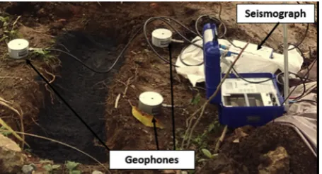
A six channel seismograph (Minimate pro 6) with two geophones and a four channel seismograph (Blastmate III) with one geophone were used to monitor the ground vi-bration. The geophones were installed in such a way that the transverse direction was parallel to the length of the trench and the longitudinal direction was perpendicular to the trench. The arrangement of the trench and the instrumentation for vibration mea-surement are shown in Figs.3and4, respectively.
Seismographs are capable in measuring vibrations in the traverse, vertical and lon-gitudinal directions up to 254 mm/s with a resolution of 0.127 mm/s in the frequency range 2 Hze250 Hz. The geophones were placed on the ground and their ground spikes were inserted (length of the spike is 65 mm) into the ground. Before measuring, they were programmed to record vibration in a continuous mode and
fixed time stop mode. Arrow marks located on the top of the geophones were pointed towards the direction of the source.
2.2. Analysis of results
Magnitudes and range of frequencies of impact pile induced ground vibration were determined from thefield measurements. In the three radial directions, maximum Peak Particle Velocities (PPVs) at each location were determined and average PPVs were calculated. The dominant frequency at each geophone location along the three radial directions were determined and maximum and minimum frequencies
were extracted and then represented as the range of frequencies. The effectiveness of the in-filled trench dimensions was quantified by using Root Mean Square (RMS) value of the ground vibrations measured in-front of the trench (L1) and behind the trench (L2) (Fig. 3).
For each ground vibration, the acceleration (ai) was determined from the records of
ground velocity by usingEq. (1).
ai¼
ðviþ1viÞ
Dt ð1Þ
Where,viand viþ1 are particle velocity readings at time stepiand iþ1, respec-tively, andDtis the sampling time (i.e., 1/1024 s).
The Root Mean Square (RMS) of particle acceleration in each ground vibration was determined by usingEq. (2).
RMS¼
ffiffiffiffiffiffiffiffiffiffiffiffiffiffi Xn
i¼1
ai2 n
s
ð2Þ
InEq. (2),aiis the acceleration value of a particular time step andnis the number of
steps within the measured time period.
The percentage of reduction in ground acceleration was determined as the damping percentage as shown inEq. (3). The ground acceleration at location L1 was not a unique value. Therefore, waveforms with similar ground accelerations at L1 were considered to determine the effectiveness of the in-filled trench in terms of damping percentage.
Damping percentage¼RMS of acceleration at L1RMS of acceleration at L2 RMS of acceleration at L1
ð3Þ
3. Results
3.1. Characterises of ground vibration induced by impact piling
Average Peak Particle Velocities (PPVs) of ground vibration in the transverse, ver-tical and longitudinal directions are compared inFig. 5.
source. They merge at about 20 m from the source and no significant difference in the vibration magnitude could be found at about 25 m (i.e., farfield).
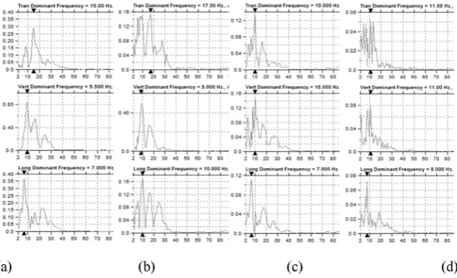
The Fast Fourier Transforms (FFT) of the ground vibrations at 5 m, 10 m, 15 m and 25 m from the source in all three directions (shown inFig. 2), caused by impact piling were obtained. Since the vibrations characteristics along all three directions were similar, data only along a single radial direction is shown inFig. 6. It can be seen that the frequency range of the vibration is contained within quite a broad band from 2e30 Hz. This falls within the frequency range of 1e80 Hz which is perceived by residents as whole body feel-able vibration[30].
Fig. 5.Average PPV variation with the distance in vertical, transverse and longitudinal directions.
3.2. E
ff
ect of width of trench
fi
lled with coal bottom ash
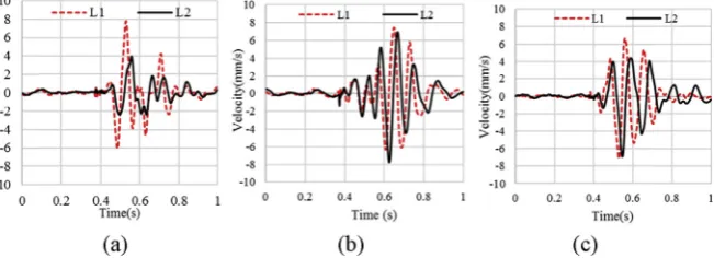
In order evaluate the effect of trench width, an experimental study was conducted by varying the trench width as 30, 60 and 90 cm while keeping the depth as constant (50 cm).Fig. 7(a)e(c) compare the ground vibrations at L1 (in front of the coal bot-tom ash in-filled trench) and L2 (behind the coal bottom ash in-filled trench) for a trench having a width of 30 cm and depth of 50 cm measured in the transverse, ver-tical and longitudinal directions, respectively. Figs.8 and9 similarly compare the ground vibrations before and after the trench (widths of 60 and 90 cm) in the three orthogonal directions. It is evident that the in-filled trench provides some degree of damping to the vibration in all three directions. The damping is more pronounced in the transverse direction than that in the other two directions. The damping of the vi-bration in all three directions seems to increase with the trench width. To capture these effects the variations of damping percentages in the transverse, vertical and longitudinal directions with the trench width are compared inFig. 10. For trench widths of 30 and 60 cm, the transverse vibration is most damped while for the trench width of 90 cm, the longitudinal vibration seems to be most damped. It can be seen that the presence of coal bottom ash in the trench reduces the ground vibration in all three directions when the trench width is increased from 30 cm to 60 cm. This trend
Fig. 7.Variation of ground vibration in (a) transverse (b) vertical and (c) longitudinal directions moni-tored at L1 and L2 for a trench of 30 cm width and 50 cm depth.
continues for the vertical and longitudinal vibrations, but the damping percentage in the transverse direction decreases dramatically when the width increases to 90 cm. In the vertical direction, the RMS of ground acceleration is reduced by 2 %, 8 % and 14 %, for trench widths of 30 cm, 60 cm and 90 cm respectively. In the longitudinal direction these reductions are 3 %, 23 % and 31 % respectively. Although a clear trend in reduction in ground vibration was not observed in the transverse direction, the RMS of ground acceleration has been reduced by 52 %, 53.5 % and 20 % for trench widths of 30 cm, 60 cm and 90 cm, respectively.
3.3. E
ff
ect of depth of trench
fi
lled with coal bottom ash
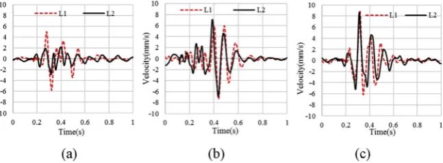
Figs.11,12, and13compare the wave form at L1 (in front of the coal bottom ash
in-filled trench) and L2 (behind the coal bottom ash in-filled trench) for trenches with depths of 50 cm, 75 cm and 100 cm, respectively. Here, the width of the trench is
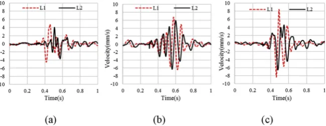
Fig. 9.Variation of ground vibration in (a) transverse (b) vertical and (c) longitudinal directions moni-tored at L1 and L2 for a trench of 90 cm width and 50 cm depth.
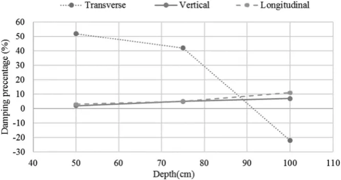
kept constant at 30 cm. The variation of maximum damping percentage in trans-verse, vertical and longitudinal with depth of the trench is compared inFig. 14. From these Figures, it can be seen that for both vertical and longitudinal vibrations, the damping increases with trench depth. This trend seems to be reversed for the transverse vibration. In the vertical direction, ground acceleration has been reduced by 2 %, 5 % and 7 % for trench depths 50 cm, 75 cm and 100 cm respectively. These reductions are 3 %, 5 % and 11 % in the longitudinal direction for trench depths of 50
Fig. 11.Variation of ground vibration in (a) transverse (b) vertical and (c) longitudinal directions moni-tored at L1 and L2 for a trench of 30 cm width and 50 cm depth.
Fig. 12.Variation of ground vibration in (a) transverse (b) vertical and (c) longitudinal directions moni-tored at L1 and L2 for a trench of 30 cm width and 75 cm depth.
cm, 75 cm and 100 cm, respectively. In the transverse direction, ground acceleration has been reduced by 52% and 41% for trench depths of 50 cm and 75 cm respec-tively. The trench with a depth of 100 cm was unable to damp the transverse ground vibration, despite a few trials. This could be due to an experimental error.
4. Model
The experimental investigation is complemented and supplemented by a numerical study on the effects of in-fill material, impact force, distance of trench from source and soil property on the ground vibration. Towards this end, the experimental inves-tigation is simulated in an axisymmetric model (Fig. 15) utilising the Abaqus FE software and the modelling techniques arefirst validated. The soil type of the site is identified as poorly graded sand (SP) according to the USCS soil classification
[27]and soil properties are selected as in the literature (Table 3). Rayleigh damping parameters are calculated utilising the method adopted in Zerwer et al.[31]. The soil media is modelled as an elastoplastic material with Mohr-Coulomb plasticity. Axisymmetric conditions is applied to model and 0.25 m uniform mesh elements (CAX4R) are selected for the model. Infinite elements (CINAX4) are utilised to simulate a non-reflecting boundary as the farfield condition, as shown inFig. 15 Fig. 14.Damping percentage variation with the variation of the depth of in-filled trench.
(b). As in the experiments, a trench is introduced at 6 m away from the source of excitation to evaluate its efficiency on vibration screening.
Prior to impact loading, gravity loading is applied to the soil elements to establish the in situ conditions. In this study, explicit scheme is used because it is suitable for high speed dynamic events such as in stress wave propagation[32]. For modelling, the impact force is calculated equating the change of momentum (MV) of the dropping weight to an impulse, with a triangular force time history and assuming an impact duration of 80 ms as shown inFig. 16. The load is pointed directly on to the surface along the axis of symmetry. The time history for one second is considered and data is extracted at each 0.001 s interval resulting in 1000 data points.
4.1. Model validation
The model is validated by comparing the numerical results with those from the experimental study. Since an axisymmetric model is developed, only the longitudi-nal and vertical components of the particle vibration are compared. Material proper-ties are listed in Table 3. Fig. 17 shows the comparison of FE model and experimental results of PPV of the free field with the distance from the source and it is evident that the two sets of results compare reasonably well. The trench
filled with coal bottom ash is then introduced with the coal bottom ash modelled as linear elastic material with Mohr-Coulomb plasticity. The damping percentage for each trench configuration is obtained by using the RMS values of accelerations
Fig. 16.Time history curve of impact load.
Table 3.Soil and Coal bottom ash properties [33,34,35,36,37,38].
Material Property Soil Coal bottom ash
Density (kg/m3) 1950 2320
Young’s modulus (MPa) 150 18
Poisson’s ratio 0.20 0.25
Friction angle (degrees) 35 37
at the nodes where the geophones were located in the experiment. The damping per-centages of different trench configurations obtained from the FE model and experi-mental results are illustrated inFig. 18. It can be seen that the FE model results follow the same trends as thefield test data with slight discrepancies. This may be due to the non-homogeneous and 3D nature in the experimental site. Overall, from Figs.17and18it can be concluded that the FE model results are in a reasonable agreement with the experimental data and the model is capable of simulating the ground vibration propagation and attenuation.
5. Results and discussion
The process of ground vibration propagation and mitigation with trenches involves many parameters. A sensitivity analysis is therefore performed to identify the effects of some of the controlling parameters on vibration propagation and ground barrier performance. The parameters used in the sensitivity analysis are presented in
Table 4. In order to have proper comparison of results, an infilled trench having a
Fig. 17.Comparison of FE model and experimental results for free field vibration (a) vertical (b) longitudinal.
width of 0.3 m and depth of 3 m is considered for further investigation. Here, the
in-fill material, vibration source, soil medium and trench location are varied to obtain their effects. Vertical and horizontal components of PPV variation with the distance from source and amplitude reduction ratio at selected distances are plotted. To calcu-late amplitude reduction ratiofirstly without a trench, responses at different distances are measured as acceleration data. Secondly, the responses at the same locations are measured with the trench in place. Thirdly, the time domain acceleration data is con-verted to frequency domain to determine the maximum spectral amplitudes of the two data sets. Subsequently, amplitude reduction ratio for each case is defined (Eq. (4)) by considering the ratio between maximum spectral amplitudes of vibra-tions that are measured pre and post installation of trench for that case.
Amplitude reduction ratio¼ Maximum spectral amplitude with trench
Maximum spectral amplitude without trench ð4Þ
5.1. In-
fi
ll material
The effect of the in-fill material is evaluated by comparing the performances of the open trench and thosefilled with coal bottom ash, Expanded Polystyrene (EPS) and water. EPS is modelled as an elastic material using material properties used in Mo-tamed et al. [32]. Ekanayake et al. [25] used Mie-Gruneisen equation of state to model behaviour of water and the same model is adopted in the present study. At the trench, some amplifications of particle vibration can be observed, especially with the open trench as shown inFig. 19. This may be due to the effects of geometric irregularities at the trench and reflected waves at the trench interface. All the trenches show some reductions of the PPVs, especially the open trench. Effects of the in-fill material is realised in the nearfield up to a distance 12 m and 8 m from the source for the longitudinal and vertical PPVs respectively. A clear effect of mitigation by the different trenches can be seen in the vertical far field vibration, while the trench type does seem not to have an effect on the longitudinal farfiled vibration. Saikia and Das[39]concluded that the open trenches are more effective in screening ver-tical vibration than the horizontal components for steady state vibration and from the present study a similar conclusion can be made for impact loading. FromFig. 20, it can be seen that the open trench and waterfilled trench show higher amplitude
Table 4.List of parameters.
Parameter Range
In-fill materials Coal bottom ash, EPS and water
Peak value of impact force 0.639, 0.959 and 1.918 MN
Elastic modulus of soil 50, 100 and 150 MPa
reduction ratios and imply better performance than the other two trenches. It is some-what obvious that open trenches are most effective as no energy transfer takes place through a void, but they are not practical for reasons stated earlier in this paper. High performance of waterfilled trench may be caused by interrupting shear wave prop-agation through a liquid phase. However, their practical applications are also limited due to wall stability and safety issues. Further, EPS material shows slightly better performance than coal bottom ash. Even though coal bottom ash was used as the
fill material in the experimental study, its effectiveness was less compared to other materials (e.g. EPS) available in the industry. Since polymers tend to have higher damping than cementations material due to their viscoelastic properties[40], bottom ash which is rich with cementations properties[26]performs less effectively in vi-bration screening. According to Liyanapathirana and Ekanayake[21]EPS geofoam
Fig. 19.PPV variation with distance for different trench configurations (a) longitudinal (b) vertical
vibration.
can be considered as an effectivefill material for ground barriers and hence EPS ma-terialfilled trenches are considered in the subsequent study on the effects of the other parameters such as impact force, soil elastic modulus and trench location.
5.2. Impact force
Effect of the impact force is studied by varying the input force function of the model. As described in the model validation section, variations in the force function are calculated by changing the impact times as 40 ms, 80 ms and 160 ms. It is evident that with increase of impact time, peak value of load function is reduced. Conse-quently, resulting ground vibration is decreased significantly as shown inFig. 21. The variations of vertical and longitudinal vibrations can be seen to be similar for the three load cases, with notable reductions in the PPVs across the in-filled trenches in all cases. AsFig. 22illustrates amplitude reduction ratios in general increase for all three impact scenarios. However, the ground vibration resulting from the highest peak load appears to have the highest damping in the presence of trench. This may be contributed by the high drop of the longitudinal component of vibration at the trench for high impact as shown inFig. 21(a).
5.3. Elastic modulus of soil
The sensitivity of elastic modules of the soil media for ground wave propagation is investigated. As exemplified inFig. 23, increase of the elastic modulus of the soil results in decrease in both the vertical and longitudinal PPVs of ground motion. A similar trend was observed byKhoubani and Ahmadi [41] who stated that even though the transmission wave velocity decrease with a reduction in the elastic modulus of the soil, level of vibration increases due to higher velocity strains. How-ever, the amplitude reduction ratios show only small variations as shown inFig. 24.
Fig. 22.Amplitude reduction ratio for different load cases.
Fig. 23.PPV variation with distance for varies soil elastic modulus (a) longitudinal (b) vertical vibration.
Thompson et al.[4] observed similar trends for train induced vibration with the change of shear wave velocity of top soil layer from 100 m/s to 200 m/s. While sites with higher ground vibration levels show high reduction in the nearfield, farfield results are comparable.
5.4. Distance from the source
The effect of trench location on vibration screening performance is studied. Three trench locations are considered and results for the longitudinal and vertical PPVs are shown inFig. 25. There is no significant variation of the PPVs observed with the change of the trench location, except in the region (4 me8 m) in which they were located. The location of the trench can hence be chosen depending on the prox-imity of the receiver to the source of vibration, However,Fig. 26 shows that the
Fig. 25.PPV variation with distance for different position of trench (a) longitudinal (b) vertical.
overall performance of the trench located at 8 m has a better performance than the other trenches implying that passive isolation can be effective for impact load induced vibration. At far field conditions however, the performance of trenches are comparable.
6. Conclusions
This paper treated the ground vibration induced due to impact pile driving and its screening with the use of trenches, using experimental and numerical techniques. Atfirst the characterises of ground vibration and the effects of a coal bottom ash
in-filled trench on screening the ground vibration induced by impact piling were inves-tigated experimentally. Freefield results show that at a distance of 10 m from the source, the PPV of the vertical wave was 4.41 mm/s while the PPVs of the transverse and longitudinal waves were 2.67 mm/s and 3.36 mm/s respectively. It is hence evident that impact pile induced vibration can cause damage in vibration sensitive structures within 10 m distance from this source based on the limiting value
identi-fied as 2 mm/s in most standards. Mainfindings of the experimental study are listed as follows:
The vertical ground vibration was dominant throughout the distance from the source.
For trenches of width 30 cm and depths of 50 and 75 cm, the transverse vibration was most damped while for the trench depth of 100 cm, the longitudinal vibration seemed to be the most damped.
When the width was increased, the ground vibration in all three directions decreased for trench widths of 30 cme60 cm. This trend continued for the ver-tical and longitudinal vibrations, but the damping percentage in the transverse di-rection decreased dramatically when the width increased to 90 cm.
Notable influence on screening ground vibration with the use of bottom ashfilled trench was observed in the vertical and longitudinal directions, but was less in the transverse direction.
To complement and supplement thefindings of the experimental investigation, a nu-merical study was undertaken using the validated modelling techniques. The effects of in-fill material, distance of trench from source, soil property and impact force on the ability of the trench to screen pile induced vibration were analysed. Based on the numerical study following conclusions can be drawn.
The amplitude reduction ratios for all trenches were reasonably unchanged with the increase in distance of trench from source.
Study on the effects of the impact force revealed that a smaller impact force at the source resulted in a significant reduction in vibration levels which may be a consideration at the design stage. However, the vibration caused by higher peak loads was damped greatly by the presence of the trench.
The amplitude reduction ratio was found to be site specific where the change of elastic modulus of soil can greatly affect vibration propagation. Sites, which have high vibrations also have lower amplitude reduction ratios at nearfield implying high damping.
Pile driving is a vital process in the construction industry in order to support larger structures such as high-rise buildings and bridges. Depending on the impact force, pile dimensions, site conditions and the type of the receiver, ground vibrations may cause discomfort to the occupants, disturb the activities carried out in the build-ings or cause damage to the structures. Therefore, it is important to evaluate the vi-bration characteristics of pile driving prior to construction. Thefinding of this study can be used to identify limits of vibration based on the type of structures in the vi-cinity, characteristics of ground vibration induced by impact pile driving and the ef-fects of trench dimensions, in-fill material, vibration source, soil medium and location of trench on vibration screening. For the case of ground vibration induced by pile driving, additional experimental and numerical investigations can be con-ducted to formulate a prediction model which can aid future research and inform design. Moreover, similar studies for ground vibration induced by other activities such as ground compaction and railway and highway traffic can be carried out to complement and supplement the present work.
Declarations
Author contribution statement
P. Jayawardana: Conceived and designed the experiments; Analyzed and inter-preted the data; Contributed reagents, materials, analysis tools or data; Wrote the paper.
R. Achuhan: Conceived and designed the experiments; Performed the experiments. S. De Silva: Performed the experiments; Analyzed and interpreted the data; Wrote the paper.
Funding statement
P. Jayawardana was supported by the Queensland University of Technology
Competing interest statement
The authors declare no conflict of interest.
Additional information
No additional information is available for this paper.
Acknowledgements
The authors wish to thank the staffand students of University of Ruhuna, Sri Lanka for help in conducting thefield experiments.
References
[1] D. White, I. Finlay, M. Bolton, G. Bearss, Press-in piling: ground vibration and noise during pile installation, in: Deep Foundations 2002: an International
Perspective on Theory, Design, Construction, and Performance, 2002,
pp. 363e371.
[2] K.R. Massarsch, B.H. Fellenius, Ground vibrations induced by impact pile driving, in: 6th International Conference on Case Histories in Geotechnical
Engineering Arlington, VA, 2008.
[3] A. Grizi, A. Athanasopoulos-Zekkos, R.D. Woods, Ground vibration measure-ments near impact pile driving, J. Geotech. Geoenviron. Eng. 142 (2016),
04016035.
[4] D.J. Thompson, J. Jiang, M.G.R. Toward, M.F.M. Hussein, E. Ntotsios, A. Dijckmans, P. Coulier, G. Lombaert, G. Degrande, Reducing
railway-induced ground-borne vibration by using open trenches and soft-filled barriers,
Soil Dynam. Earthq. Eng. 88 (2016) 45e59.
[5] IS-6922, Criteria for Safety and Design of Structures Subjected to under Ground Blast, 1973.
[6] M. Monjezi, M. Ahmadi, M. Sheikhan, A. Bahrami, A.R. Salimi, Predicting blast-induced ground vibration using various types of neural networks, Soil
Dynam. Earthq. Eng. 30 (2010) 1233e1236.
[7] D.E. Siskind, M.S. Stagg, J.W. Kopp, C.H. Dowding, Structure response and damage produced by ground vibration from surface mine blasting, in: RI 8507,
[8] A.P. Johnson, W.R. Hannen, Vibration limits for historic buildings and art col-lections, J. Preserv. Technol. 46 (2015) 66e74.
[9] DIN 4150-3, Structural VibrationePart 3: Effects of Vibration on Structures, DIN Germany Institute, Germany, 1999.
[10]American Association of State Highway and Transportation Officials, Standard Recommended Practice for Evaluation of Transportation-related
Earthborne Vibrations, Washington, DC, 1990.
[11]SN 640 312, Effects of Vibration of Construction, Zurich, Switzerland, 1978. [12]BS7385-2, Evaluation and Measurement for Vibration in Buildings, British
Standard, 1993.
[13]DGMS Circular 7, Damage of the Structures Due to Blast Induced Ground Vibration in the Mining Areas, India, 1997.
[14]B.B. Dhar, P. Pal Roy, R. Singh, Optimum Blasting for Indian Geo-mining Conditions Suggestive Standard and Guidelines, CMRI Publication, India,
1993.
[15]P.K. Singh, M.P. Roy, Damage to surface structures due to blast vibration, Int. J. Rock Mech. Min. 47 (2010) 949e961.
[16]M. Svinkin, Minimizing construction vibration effects, Pract. Period. Struct. Des. Construct. 9 (2004) 108e115.
[17]R.D. Woods, Dynamic Effects of Pile Installations on Adjacent Structures, 1997.
[18]E. Çelebi, S. Fırat, G. Beyhan,_I. Çankaya,_I. Vural, O. Kırtel, Field experi-ments on wave propagation and vibration isolation by using wave barriers,
Soil Dynam. Earthq. Eng. 29 (2009) 824e833.
[19]A. Garinei, G. Risitano, L. Scappaticci, Experimental evaluation of the effi -ciency of trenches for the mitigation of train-induced vibrations, Transp.
Res. Part D: Transp. Environ. 32 (2014) 303e315.
[20]D. Ulgen, O. Toygar, Screening effectiveness of open and in-filled wave bar-riers: a full-scale experimental study, Construct. Build. Mater. 86 (2015)
12e20.
[21]D.S. Liyanapathirana, S.D. Ekanayake, Application of EPS geofoam in atten-uating ground vibrations during vibratory pile driving, Geotext. Geomembr.
[22]F.E. Richart, J.R. Hall, R.D. Woods, Vibrations of Soils and Foundations, Prentice-Hall, Englewood Cliffs, N.J., 1970.
[23]K.R. Massarsch, Ground vibration isolation using gas cushions, in: Second In-ternational Conference on Recent Advances in Geotechnical Earthquake
Engi-neering and Soil Dynamics (1991: March 11-15; St. Louis, Missouri),
formerly the University of Missouri–Rolla, Missouri S&T, 1991.
[24]P. Zoccali, G. Cantisani, G. Loprencipe, Ground-vibrations induced by trains:
filled trenches mitigation capacity and length influence, Construct. Build. Mater. 74 (2015) 1e8.
[25]S.D. Ekanayake, D.S. Liyanapathirana, C.J. Leo, Attenuation of ground vibra-tions using in-filled wave barriers, Soil Dynam. Earthq. Eng. 67 (2014)
290e300.
[26]W.A.P.D. Jayawardana, G.H.M.J. Subashi De Silva, G.S.Y. De Silva, Eff ec-tiveness of a trenchfilled with waste material in reducing the propagation of
ground vibration induced by soil roller compaction, Eng.: J. Inst. Eng. Sri
Lanka 49 (2016).
[27]ASTM-D2487-11, Standard Practice for Classification of Soils for Engineer-ing Purposes (Unified Soil Classification System), 2011.
[28]M.P. Kadam, Y.D. Patil, Effect of sieved coal bottom ash as a sand replace-ment on the properties of cereplace-ment concrete, Mag. Concr. Res. 67 (2015)
227e234.
[29]C.S.K.R. Anthony, A.J.M.S.S. Abeykoon, G.H.M.J. SubashiDeSilva, Proper-ties of masonary blocks manufactured with botom ash, in: Proceedings of 2nd
Annual Sessions of the Society of Structural Engineers Sri Lanka, 2012,
pp. pp17epp23.
[30]M.J. Griffin, Handbook of Human Vibration, Academic press, London, 1990. [31]A. Zerwer, G. Cascante, J. Hutchinson, Parameter estimation infinite element simulations of Rayleigh waves, J. Geotech. Geoenviron. Eng. 128 (2002)
250e261.
[32]R. Motamed, K. Itoh, S. Hirose, A. Takahashi, O. Kusakabe, Evaluation of wave barriers on ground vibration reduction through numerical modeling in
Abaqus, in: SIMULIA Customer Conference 2009, London, England, 2009,
pp. 402e419.
[35] Geotechdata.info, Soil Friction Angle, 2013. http://www.geotechdata.info/ parameter/angle-of-friction.html.
[36]L. Ba1achowski, Z. Sikora, Mechanical properties of bottom ashedredged ma-terial mixtures in laboratory tests, Stud. Geotech. Mech. 35 (2013) 3e11. [37]B. Kim, M. Prezzi, R. Salgado, Geotechnical properties offly and bottom ash
mixtures for use in highway embankments, J. Geotech. Geoenviron. Eng. 131
(2005) 914e924.
[38]J. Chimenos, A. Fernandez, L. Miralles, J. Rosell, A.N. Ezquerra, Change of mechanical properties during short-term natural weathering of MSWI bottom
ash, Environ. Sci. Technol. 39 (2005) 7725e7730.
[39]A. Saikia, U.K. Das, Analysis and design of open trench barriers in screening steady-state surface vibrations, Earthq. Eng. Eng. Vib. 13 (2014) 545e554. [40]D. Chung, Materials for vibration damping, J. Mater. Sci. 36 (2001)
5733e5737.


![Table 3. Soil and Coal bottom ash properties [33, 34, 35, 36, 37, 38].](https://thumb-us.123doks.com/thumbv2/123dok_us/9703635.1498015/14.544.197.427.536.663/table-soil-coal-ash-properties.webp)
