GSJ: Volume 7, Issue 3, March 2019, Online: ISSN 2320-9186
www.globalscientificjournal.com
M
ODELLING
&
S
IMULATION OF
A
CTIVE
P
OWER
F
ILTERS FOR
C
OMPENSATION OF
3-
ɸ
S
YSTEM
H
ARMONICS
Dr. KIRAN R ABRAHAM F
Assistant Professor Lecturer
Department of Electrical & Computer Engg. Dept. Of E & C Engg.
Ambo University Ethiopia . Ambo University Ethiopia
Abstract: The present work describes the active filter operation characteristics and develops standard ratings that can be
used for filtering different types of nonlinear loads. In addition, there are filters that do not filter any frequencies of a
complex input signal, but just add a linear phase shift to each frequency component, thus contributing to a constant time
delay. These are called all-pass filters. Active filters are circuits that use an operational amplifier (op amp) as the active
device in combination with some resistors and capacitors to provide an LRC-like filter performance at low frequencies. This
work focuses simulation & modeling of standard Active filters and tests it for different Non-linear Load Harmonics. Due
to sensitivity of consumers on Power quality and advancement in Power Electronics, Active Power Filters (APF) continue to
attract considerable attention. APF technology is the most efficient way to compensate reactive Power and cancel lower
order harmonics generated by nonlinear loads.
Key-words: Active Power Filters (APF), operational amplifier (op amp), Pulse Width Modulation (PWM),
I. INTRODUCTION
Increasing demand of electric and electronic instruments including non-linear loads (e.g. computers, power electronic inverters and induction furnace) necessitates investigations about stability maintenance, continuous energy serving and power quality considering economic concerns. Non-linear loads result in voltage and current harmonics in distribution network. Harmonics provide main problems in network like power losses and excess heat. Thus, harmonic elimination seems to be vital. Nowadays, active power filters (APF) play
A filter is a circuit that is designed to pass a specified band of frequencies while attenuating all the signals outside that band. It is a frequency selective circuit. The filters are basically classified as active filters and passive filters. The passive filter networks use only passive elements such as resistors, inductors and capacitors. On the other hand, active filter circuits use the active elements such as op-amps, transistors along with the resistors, inductors and capacitors.
Advantages of active filters:
2. In large quantities, the cost of the integrated circuit can be much lower than its equivalent passive network.
3. Due to availability of modern ICs, variety of cheaper op-amps is available.
4. Due to flexibility in gain and frequency adjustments, the active filters can be easily tuned.
5. The op-amp has high input impedance and low output impedance hence the active filters using op-amp do not used loading of the source or load. 6. The design procedure is simpler than that for the
passive filters.
7. Active filters can provide voltage gains in contrast the passive filters often show a significant voltage loss.
The shunt active filter is used to compensate the current harmonic distortion to power system harmonics. To verify the operating performance of the designed filters is carried out and experimental results are obtained and discussed. In this work, the simulation of an active filter system is developed Simulink.The simulation circuit will include all realistic components of the system. This enables the calculation of currents and voltages in different parts of the overall system. Implementation has been done in Simulink.Study of hysteresis control schemes based on unipolar PWM and also Park’s transformation has been done. Simulation results are given for different operations.
1.2 Motivation and Approach
Several modelling technique have been suggested in the literature which are used to recognize and extract harmonic distortions which are classified as frequency, time and time-frequency approaches. Fast Fourier Transformer (FFT) and adaptive neural network in frequency domain, synchronous reference frame theory d-q-o (SRF) [3] and instantaneous active and reactive power theory (p q r) in time domain and the other methods such as small wave technique and one-cycle control or separation with suitable digital or analogue
In this work, reference frame algorithm is used due to simplicity in calculation and implementation. Having measured three-phase currents in a-b-c orientation, transformed to d-q-o by park transformation. This practice reduces time, cost and ensures that requirements are achieved. A hysteresis band current control based on unipolar PWM has also been designed for the closed loop operation of the system [7].
II. DESCRIPTION OF ACTIVE FILTERS
WITH NON LINEAR LOAD HARMONICS:
2.1 Active Filter Configuration
Figure 1. Block Diagram of Overall Project.
2.2 Non Linear Load
Figure 2 Current Waveform for Non linear load
2.3 Unipolar PWM Control techniques
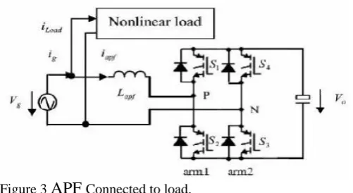
Figure 3
APF
Connected to load.Unipolar PWM uses +Ve and zero to make positive outputs and –Ve and zero to make negative outputs. Switching Harmonic Content in this case will be small and will be zero at zero crossings. Filtering will be easy in this case. Consider a full bridge single-phase inverter schematic connected in parallel to a non-linear load as shown in fig.3.The inverter can be controlled in unipolar PWM method.
There are four switching states in this approach. In unipolar control, when Vg>0 (reference current in ascendant slope dic/dt>0), S3 is on in the reference current half cycle, SI and S2 turn on and off periodically in switching cycles. Thus Vo and zero voltages produce between P and N so error signal slope is negative in hysteresis band and periodically decreases and increase. Originated current variations in reference current half cycle is as follows:
First half cycle of switching……… (1)
Second half cycle of switching……….. (2)
III. Modelling of Standard Active Filter
3.1 Reference Extraction Circuit
Fig 4 Reference Extraction Circuit.
Conduction and switching losses of diodes and IGBTs in inverters increase voltage ripple in DC-link which affects the performance of the filter. These effects controlled by a feedback loop where PI regulator compares the DC-link voltage with a reference voltage to extract d component of current. In this approach, reference frame algorithm is used due to simplicity in calculation and implementation. Having measured three-phase currents in a-b-c orientation, transformed to d-q-o by park equation. Reference frame rotates synchronous with fundamental currents. Therefore, time variant currents with fundamental frequencies would be constant after transformation. However, harmonics with different speeds remain time variant in this frame. Thus, currents would be separate simultaneously to DC and AC parts. Figure 4 shows the synchronous d-q-0 reference frame based compensation algorithm.
PI controllers consist of a proportional gain that produces an output proportional to the input error and an integration to make the study state error zero for a step change in the input. The controller output is given by
……… (3) where Δ is the error or deviation of actual measured value (PV) from the set-point (SP).
Δ = SP - PV.
A PI controller can be modelled easily in software such as
Simulink using a "flow chart" box involving Laplace
operators:
……… (4) Where,
G = KP = proportional gain G / τ = KI = integral gain
Setting a value for G is often a trade-off between decreasing overshoot and increasing settling time. The integral term in a PI controller causes the steady-state error to reduce to zero, which is not the case for proportional only control in general.
3.2 Pulse generaton technique by hysteresis current control technique.
Harmonics provide main problems in network like power losses and excess heat. Thus, harmonic elimination seems to be vital. Nowadays, active power filters (APF) play effective role in distortion recognition and elimination. These filters are classified with respect to distortion determination strategy, inverter control techniques, inverter topologies and their connection types to the grid. Current control technique based on unipolar PWM provides better stability and compensation with loss reduction; efficiency increment and dc offset elimination compare to bipolar PWM technique. Our project presents a hysteresis current control technique based on unipolar Pulse Width Modulation (PWM) with time and magnitude errors control to reduce switching losses and to improve the quality of output current.
Figure 5 Hysteresis Band Current Controller
In this approach the current error, (difference between the reference and inverter currents) is controlled in hypothetical control band surrounding reference current as shown in Fig.5.2. Reference currents are generated by DC to AC converters using a current control technique such as a hysteresis control. The hysteresis band is used to control load currents and determine switching signals for inverters gates. Suitable stability, fast response, high accuracy, simple operation, inherent current peak limitation and load parameters variation independency make the hysteresis current control as one of the best current control methods of voltage source inverters.
………….. (5)
3.3 Hysteresis Current Control Based On Unipolar PWM
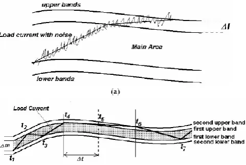
Figure 6 (a) Noisy load current with upper and lower bands. (b) Unipolar current control based on time and magnitude
error control.
In Figure 6 (b) the second upper or lower band values can be big enough in order to remove the noise issue of the inverter output current but the second decision to change the level is based on time error. For example, when the load current exceeds the first upper band at t4, the output voltage of inverter is change from +Vo to 0. The controller waits for Δt, if the inverter output current does not cross the second upper band within this period, then the controller changes the output voltage from zero to –Vo at t5. In this case, when the slop of reference current is close to the slop of inverter output current, then the time error control improves the quality of the APF and pushes the inverter current into the main area.
IV.
IMPLEMENTATION
OF
ACTIVE
FILTER MODEL WITH ITS CONTROL
TECHNIQUE:
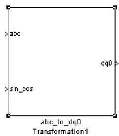
The abc phase transformation to dq0 variables is built using Park’s transformation and for the dq0 to abc the reverse transformation is used. This block performs the abc to dq0 axes Vd, quadratic axes Vq and zero sequence V0 quantities in a two axes rotating reference frame.Park’s transformation used for converting Vabc to Vdq0 [2].Park’s transformation used for converting Vabc to Vdq0 is shown below.
.
abc to dq0 transformation
Figure 4.1
dqo to abc transformation
This block transforms three quantities (direct axes, quadrature axes and zero-sequence components) expressed in a two axes reference frame back to phase quantities.
Figure 4.2
The following transformation is used:
Figure 4.3
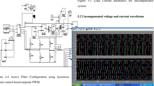
Simulink model for compensation of system harmonics using active filter and hysteresis current control based on unipolar PWM is shown in figure 4.4.
Figure 4.4 Active Filter Configuration using hysteresis current control based unipolar PWM.
V Results & Discussion
The system built in Simulink for an active filter configuration has been tested with non linear load using hysteresis current control based on unipolar PWM.
Hysteresis current control based on unipolar PWM is used for control purpose. The plots of current, voltage and
Figure 5.1 Load Current harmonics for uncompensated system
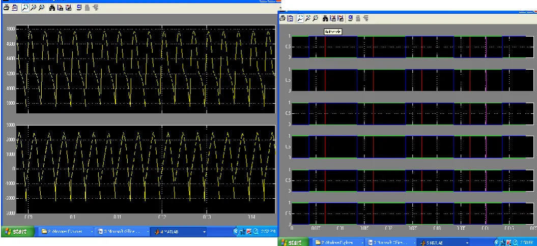
5.2 Uncompensated voltage and current waveforms
5.3 Active and Reactive Power Harmonics waveforms
Figure 5.3 Active and Reactive Power Harmonics
5.4 Closed Loop Active and Reactive Power waveforms
Figure 5.4 Closed Loop Harmonics
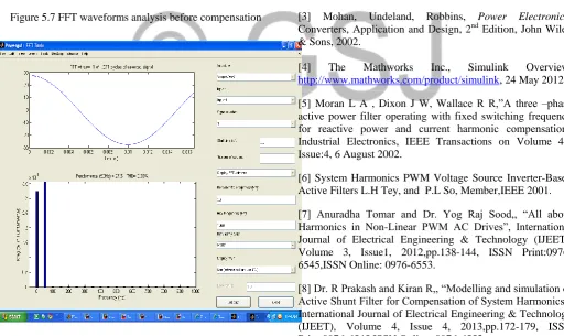
5.5 Generation of Pulse by using Hysteresis Current
Control based on Unipolar PWM technique
5.5 Pulses by hysteresis current control
5.6 Compensated waveforms output
5.7 FFT Analysis for uncompensated and compensated
harmonics
Figure 5.7 FFT waveforms analysis before compensation
Figure 5.8 FFT waveforms analysis after compensation
hysteresis current control for active power filters based on time and magnitude errors control in order to improve the quality of output current and switching losses. The simulation result shows that for a same THD (total harmonic distortion) unipolar modulation has lower switching losses. Power quality improvement can be achieved in a distribution network using this control approach in active power filters.
Performance can be further improved by an improvement in the design of the extraction circuit.
Performance can be further improved by an improvement in the design of the PWM control circuit.
VII REFERENCES
[1] J. Sebastian, Juan W. Dixon, et.el. “A Simple frequency- independent method for calculating the reactive and harmonic current in a non-linear load”, IEEE transactions on industrial electronics Vol. 43. No. 6, December 1996.
[2] W. H. Daniel, Introduction to Power Electronics, Upper Saddle River,N.J.: Prentice Hall, 2000.
[3] Mohan, Undeland, Robbins, Power Electronics:
Converters, Application and Design, 2nd Edition, John Wiley & Sons, 2002.
[4] The Mathworks Inc., Simulink Overview,
http://www.mathworks.com/product/simulink, 24 May 2012. [5] Moran L A , Dixon J W, Wallace R R,”A three –phase active power filter operating with fixed switching frequency for reactive power and current harmonic compensation” Industrial Electronics, IEEE Transactions on Volume 42, Issue:4, 6 August 2002.
[6] System Harmonics PWM Voltage Source Inverter-Based Active Filters L.H Tey, and P.L So, Member,IEEE 2001. [7] Anuradha Tomar and Dr. Yog Raj Sood,, “All about Harmonics in Non-Linear PWM AC Drives”, International Journal of Electrical Engineering & Technology (IJEET), Volume 3, Issue1, 2012,pp.138-144, ISSN Print:0976-6545,ISSN Online: 0976-6553.
[8] Dr. R Prakash and Kiran R,, “Modelling and simulation of Active Shunt Filter for Compensation of System Harmonics”, International Journal of Electrical Engineering & Technology (IJEET), Volume 4, Issue 4, 2013,pp.172-179, ISSN Print:0976-6545,ISSN Online: 0976-6553.