K E Y W O R D S
H I G H L I G H T S
A B S T R A C T
G R A P H I C A L A B S T R A C T
57
Research Paper
Received 2016-03-21 Revised 2016-06-14 Accepted 2016-06-14 Available online 2016-06-14
CO2 absorption Membrane contactor Flat sheet
Modeling and simulations
• PVDF flat sheet membrane is employed for absorption of CO2 from gas mixture. • Aqueous sodium hydroxide solution is used as the absorbent liquid
• We developed a 3D mathematical model to describe the process and solved by COMSOL. • The effect of NaOH concentration and inlet gas and liquid rate on separation was studied. • The model predictions were in good agreement with experimental data.
Modeling and Experimental Study of Carbon Dioxide Absorption in a Flat Sheet Membrane
Contactor
Department of Chemical & Petroleum Engineering, UAE University, Al-Ain city, United Arab Emirates
Nayef Ghasem*, Mohamed Al-Marzouqi
A R T I C L E I N F O
© 2017 MPRL. All rights reserved.
* Corresponding author at: Phone/fax: 971 3 713 5313 E-mail address: [email protected] (N. Ghasem)
DOI: 10.22079/jmsr.2016.20226
1. Introduction
Global warming is caused by the emission of greenhouse gases. Carbon dioxide (CO2) is the primary greenhouse gas emitted through various human activities [1, 2]. Therefore, there is a definite need for developing efficient and novel separation processes for removal of CO2 from gas streams [3, 4].
The conventional absorption processes are packed columns. The packed towers are large in size and require high investment cost and suffer from operational limitations include flooding, entrainment and foaming. Recent -ly, membrane contactor has been attracted the attention of many researchers
[5]. Using a membrane contactor system, absorption of CO2 takes place in
a compact membrane module when the gas stream contacts with the liquid phase flowing on the opposite side of the membrane. Gas-liquid membrane contacting process can overcome the drawbacks of conventional packed bed column to some extent [6]. Researchers expected that gas-liquid membrane contactor is a promising technology and can be considered as an alternative process to the conventional absorption columns. The gas-liquid membrane contactor process combines the advantages of providing compactness with very high contact area [7]. This system is not exposed to flooding, channeling
Journal of Membrane Science & Research
journal homepage: www.msrjournal.com
In the present study, CO2 removal from natural gas stream has been studied using a flat sheet membrane contactor. A three dimensional mathematical model is developed to describe the process. The model considers the transport of a gas mixture containing carbon dioxide and methane through a flat sheet membrane contactor module. The model is based on the non-wetted mode of operation, in which the gas fills the membrane pores in a countercurrent gas-liquid contact. Simulation was performed using computational fluid dynamics (CFD) of the model material and momentum transport equations in the flat sheet membrane for laminar flow conditions. Physical and chemical absorptions were considered in the simulations for the absorption of CO2 in aqueous sodium hydroxide solution. Simulation predictions were in good agreement with the experimental data for different values of gas flow rates. The modeling predictions indicate that the removal of CO2 increased with increasing inlet liquid flow rate and increasing solvent temperature, by contrast, increase in inlet gas flow rate has negative effect.
N. Ghasemand M. Al-Marzouqi / Journal of Membrane Science and Research 3 (2017) 57-63
and foaming problems which may take place in the traditional packed columns. A comprehensive review of the developments in membrane-based technologies for CO2 capture was covered by Luis et al. [8]. The research on
CO2 capture from flue gas and natural gas using gas-liquid hollow fiber membrane contactor has been studied by a number of researchers [9–19].
Various mathematical models have also been proposed to describe the capture of CO2 from gas mixture using gas-liquid hollow fiber membrane contactors. The models were validated with experimental results to verify and predict the consequences of varying operating parameters and structure of hollow fiber membranes on contactor absorption performance. A mathematical model that describes the SO2 absorption in hollow fiber ceramic
membrane contactor was developed by Luis et al. [20]. Several other numerical models were developed to describe the influence of membrane wetting on CO2 capture in hollow fiber membrane contactor. These models were based on resistance-in-series [21-23]. Moreover, the influence of pore size, pore size distribution and effective surface porosity on membrane mass transfer coefficient was studied by Li et al. [24]. Mavroudi et al. [25] studied the membrane resistance change with time of physical absorption of pure CO2. Gas liquid membrane contactor can also be used for stripping CO2 from amine solution [26]. However, most of the mathematical models focused on hollow fiber membrane contactor. To the best of our knowledge none was developed for flat sheet membrane contactor using three dimensional (3D) approach for the absorption of CO2 from natural gas using aqueous NaOH solvent.
The aim of the present work was to develop a 3D mass transfer model for absorption of CO2 from natural gas in a flat sheet membrane contactor. Aqueous NaOH solution is considered as the chemical solvent in simulations. Computational fluid dynamic technique is used for numerical simulation, and results of simulations are then compared with experimental data. The experimental work was performed via microporous PVDF flat sheet membrane casted through thermally induced phased separation (TIPS) technique. The in-lab made PVDF flat sheet membrane contactor modules were used in the absorption of CO2 from a gas mixture that consists of 10%
CO2/90%CH4 through a 0.5 M NaOH solution.
2. Model development
Material and momentum transport equations were considered in the development of the mathematical model. The proposed model describes the transport of gas mixture and liquid solvent in a countercurrent flat sheet membrane contactor [27-29]. The steady state model equations developed for module segment are shown in Figure 1.
2.1. Gas phase
The steady state continuity equation is used for the prediction of carbon dioxide concentration in the gas phase:
C C C C 2 g -i 2 2 g -i 2 2 g -i 2 i g -y z y x D y
v i-g (1)
where
g y
v
refers to the velocity of the gas phase in y-direction,C
i-g is theconcentration of carbon dioxide in gas phase along the length of the membrane. The model is built up for non-wetting mode of operation (i.e. gas filled pores). Under countercurrent mode of operation, the following boundary conditions exist:
2
z
z
,
C
i,g
C
i,m identical concentration at the membrane-gas interface(2)
3 z
z
,
, 0
x
Cis module walls
(3)
0
y
, ,
0
x
C
igConvective flux, outlet of gas stream (4)
L
y ,
C
=
C
2 2, CO CO
g ,
C
CH4,=
C
CH4 g inlet gas stream (5)
0
x
andx
w
; , 0
x Cig
membrane module side walls (6)
The velocity distribution in the gas phase is calculated using Navier-Stokes equation. 2 2 2 2 2 2 z u y u x u x p g z u w y u v x u u t u x (7)
Boundary conditions for the Navier-stokes equations may be written as:
0
;u u L
y inlet gas velocity (8)
atm
P P
y0; gas outlet stream (9)
0
;
2
z
u
z
membrane-gas interface (10)0 ;
3
z u
z gas chamber top wall (11)
0 ; ;
0
x wu
x module side walls (12)
where uis the velocity in the y-direction, L is the length of membrane, w is the width of the membrane.
2.1.2. Membrane section
The steady-state material balance for the transport of CO2 and CH4 along
the membrane thickness for non-wetting mode of operation is considered to be due to diffusion only; no reactions are taking place in the gas filled pores (i = CO2 and CH4).
Fig. 1. Schematic diagram of flat sheet membrane contactor used for CO2 capture.
0 2 , 2 2 , 2 2 , 2 , z C y C x C
D im im im
m
i (13)
Boundary conditions:
1
z
z
,i l i m
i
C
m
C
,
,/
membrane-liquid interface (14)2
z
z
,l i m
i
C
C
,
, membrane-gas interface (15)0
y , yL, , 0
z
Cim Thermal insulation at both
ends of membrane walls
(16)
0
x
andx
w
; , 0 y
Cim membrane walls
(17)
where mi is the solubility CO2 and CH4 in aqueous sodium hydroxide
solution.
2.1.3. Liquid side
The steady-state material balance for the transport of CO2 and aqueous
NaOHin the liquid side of the flat sheet membrane is considered to be due to diffusion, convection and reaction as well. The reaction overall rate can be determined depending on its mechanisms and reaction rates. The right hand side of the following equation represents the diffusion and reaction terms, whereas the left hand side of the equation is the convective term [20-22].
C C C C 2 l -i 2 2 l -i 2 2 l -i 2 i l
-y i-l ri
z y x D y
v
(18)
where the subscript “i” indicates carbon dioxide and sodium hydroxide.
Reaction rates for CO2 and NaOH are shown in equations 20 and 21,
respectively: O H CO Na CO
NaOH 2 2 3 2
2 (19)
l NaOH l CO r
CO
k
C
C
r
2,t
2, , (20)l NaOH l CO r t
NaOH
k
C
C
r
,
2
2, , (21)Boundary conditions:
The boundary conditions for solvent flowing in liquid compartment of the flat sheet membrane are shown below (i = CO2 and NaOH):
1
z
z
,m i i l
i
= m
C
C
, . gas solubility in solvent at liquid-membrane interface
(22)
0
z
, , 0
z
Cil module wall (23)
0
y
,C
NaOH,l= C
NaOH solvent initial feed concentration (24)L
y
, , 0
y
Cil liquid exit stream
(25)
0
x
,x
w
; , 0
y
Cil module left and right side walls
(26)
The velocity distribution in the liquid phase is calculated using Navier-Stokes equations: 2 2 2 2 2 2 z u y u x u x p g z u w y u v x u u t u x (27)
Boundary conditions for the Navier-stokes equations can be written as:
0
;
0
u
u
y
inlet liquid velocity (28)atm
P P L
y ; liquid side outlet flow (29)
0
;
0
u
z
liquid side bottom wall (30)0 ;
1
z u
z liquid-membrane interface (31)
0 ; ;
0
x wu
x liquid chamber left and right side walls (32)
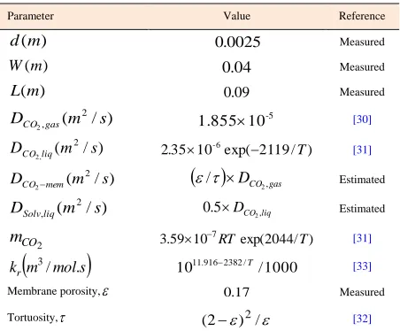
Model parameters are shown in Table 1. Physical properties such as density and viscosity as a function of temperature and pressure are built in COMSOL software, for the absorbent liquid, the property of water is being assumed.
Table 1
Numerical values of the parameters used for modeling.
Parameter Value Reference
)
(
m
d
0.0025 Measured) (m
W 0.04 Measured
) (m
L 0.09 Measured
)
/
(
2 ,2
m
s
D
CO gas-5
10
1.855 [30]
) / ( 2 ,
2 m s
DCOliq 2.3510-6exp(2119/T)
[31]
) / ( 2
2 m s
DCOmem
/
DCO2,gas Estimated)
/
(
2,
m
s
D
Solvliq 0.5DCO2,liq Estimated2 CO
m
3.59107RTexp(2044/T) [31]
m mols
kr / .
3
1000 /
1011.9162382/T [33]
Membrane porosity,
0.17 Measured Tortuosity, (2)2/ [32]3. Experimental work
3.1. Materials
Poly (vinylidene fluoride) (PVDF) (Solef® 6020/1001) was purchased
from Solvay company, France. Glycerol triacetate (triacetin), ethanol and sodium hydroxide were purchased from Sigma-Aldrich; all materials were with purity more than 99%. All chemicals were used as received without further purification. Gas mixture (e.g. 10 vol% CO2, 90 vol% CH4) cylinder
was purchased for Air Product (UAE). Two types of epoxy were used: at room temperate, Araldite 5 minutes rapid, Belgium. For high temperature Emerson Stycast 2651W-Catalyst 9 (operating temperature: -40 to 130 oC)
was purchased from Ellsworth Adhesive Ltd. (UK).
3.2. Preparation of flat sheet membrane module
Various polymeric flat sheet membranes were casted for CO2
removalfrom CO2/CH4 gas mixture. Polyether sulfone (PES) and
Polyvinylidene fluoride (PVDF) were used for fabricating the flat sheet membranes. Selected amount of polymer was mixed with N, N -Dimethylacetamide (DMAc) in ratio of 1:4. The PES mixture was kept overnight in order to produce homogenous mixture at room temperature. By contrast, heating is used for the preparation of PVDF/DMAc dope solution. The homogenous transparent dope solution was then spread on a Pyrex glass and it was balanced from all edges using casting machine in order to get a uniform thickness. The Pyrex glass along with the dope solution was then immersed in deionized water at room temperature for one day. The solvent is transferred into water and the dope mixture is agglomerated and formed polymeric flat sheet membrane. The membrane was then drayed in a freeze dryer in order to remove any moisture left. Afterward, it was cut to 4 × 9 cm to fit with the exact available space in the flat sheet module.
N. Ghasemand M. Al-Marzouqi / Journal of Membrane Science and Research 3 (2017) 57-63
Fig. 2. Experimental setup used for CO2 absorption experiments.
Fig. 3. Surface plot (3D) of carbon dioxide concentration in flat sheet membrane generated with COMSOL 5.1.
The schematic diagram of the experimental setup used in CO2 absorption
is shown in Figure 2. The experimental setup consists of a flat sheet module (consists of two compartments separated by flat sheet polymeric membrane). Gas and liquid streams enters the module in countercurrent flow. Flow rates are controlled by mass flow controllers (Alicat, USA). The solvent (NaOH) flow rate is adjusted through a peristaltic pump (Masterflex, USA). The effect of inlet absorbent temperature on system performance was investigated. The gas free water vapor is sent to the gas chromatography (Shimadzu, Japan). The gas chromatography analysis is used to measure the CO2 concentration in
the exit gas stream. The experimental operating conditions are shown in Table 2.
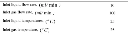
Table 2
The operating conditions used in the absorption experiments, at 1 atm.
Inlet liquid flow rate, (ml/min) 10 Inlet gas flow rate, (ml/min) 100 Inlet liquid temperatures, (oC) 25
Inlet gas temperature, (oC) 25
4. Results and discussion
A mathematical model for the transport of CO2 through the proposed
PVDF flat sheet membrane contactor module has been developed with aqueous NaOH as the absorbent liquid. Non-wetting mode of operation is considered. The model equations were solved using COMSOL 5.1. The computational time for the simulation is 14 seconds using computer Intel CORE i7. The model prediction of surface plot for carbon dioxide concentration across the membrane is shown in Figure 3. The model equations were solved for investigating the effect of gas and liquid flow rates, solvent temperatures and various NaOH concentration on membrane performance. The objective of simulation is to study the effect of operational
conditions on the system performance, i.e. the percent of CO2 removal. By
assuming equal inlet and outlet gas streams, the amount of removed CO2 does
not affect the gas flow rate [8].
in CO
out CO in CO
C C C
, , ,
2 2
2
(33)
The CO2 removal flux
s out CO in CO in CO
A C C Q
J 2, 2,
2
(34)
where
2 CO
J is the removal flux of CO2 (mol/m2s),
A
s is the totalmembrane area (m2),
in
Q
is the gas volumetric flow rates (m3/h)and
in CO
C
2,and
out CO
C ,
2
are the CO2 molar concentrations in the gas phase
(mol/m3) at the inlet and outlet streams, respectively. Moreover,
refers tothe CO2 removal fraction. Since the maximum CO2 concentration of the inlet
gas mixture is very low, the change in volumetric flow rate is assumed to be negligible. Thus removal efficiency can be approximated by Eq. (33). The exit gas concentration (
out CO
C 2,
) is derived by means of surface average. The
removal flux is calculated by Eq. (34). Concentration distribution of CO2 in
the gas phase is the most important parameter for optimization of process. Decreasing CO2 concentration in the gas phase determines the CO2 removal
rate. The surface plot of the concentration of CO2 in the liquid, membrane and
gas compartments of the membrane contactor module are shown in Figure 3. The gas mixture flows into the gas side of the contactor (at y = L) where the concentration of CO2 is the highest. On the other hand, NaOH solution flows
into the liquid compartment side (at y = 0), where the concentration of CO2 is
penetrated CO2 to the liquid side is absorbed by the flowing solvent, where it
reacts and gets consumed. In the liquid and gas compartments, the flux vectors are in both the x and the y directions. This is due to convection and diffusion; whereas within the membrane, the flux vectors are in two z -directions due to diffusion only. In the membrane side, only diffusion is taking place.
4.1. Axial concentration profile
The axial concentration of CO2 along the gas-membrane interface is
illustrated in Figure 4. The CO2 concentration decreases along the
gas-membrane interface till it reaches the minimum value at the outlet of the membrane contactor module. This is attributed to the consumption of carbon dioxide along the length of the membrane due to the progress in reaction rate.
Fig. 4. Predicted axial CO2 concentration profile at tube-membrane interface
along membrane length.
4.2. Model validation
The 3D mathematical model was solved using COMSOL 5.1 software package. The modeling predictions for the physical and chemical absorption of 10% CO2 in the 0.5 M aqueous sodium hydroxide solvent (using a flat
sheet PVDF membrane contactor) are compared with the experimental data. The membrane geometry and operating parameters used in the simulation are shown in Table 1. The experimental uncertainty in the experimental data is ± 2.3%. As could be observed in Figure 5, the model predictions are in good agreement with the experimental data at different values of inlet gas flow rate in the module. It is worth quoting that an average deviation of less than 10% was calculated between experimental and simulation results.
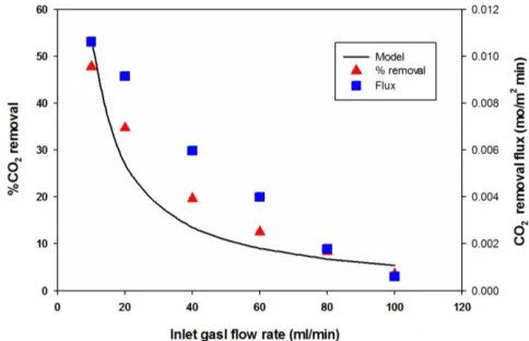
Fig. 5. Comparison of modeling predictions (solid line) and experimental data (triangle) for the percent CO2 removal and (square) for CO2 removal flux at variable
inlet gas flow rate in the module.
4.3. Effect of aqueous NaOH concentration
The experimental data for the effects of solvent concentration on removal efficiency and removal flux are illustrated in Figures 6 and 7, respectively. As could be observed, increasing the solvent concentration improves the removal
efficiency and the removal flux of CO2. This is attributed to the fact that the
active absorption of carbon dioxide at liquid boundary layer is increased with increasing solvent concentration. Since the reaction rate is a function of the CO2 and NaOH concentrations, an increasing in NaOH concentration
enhances the reaction rate. As a consequence, it increases the consumption rate of carbon dioxide.
Fig. 6. Effect of aqueous NaOH concentration on the percent of CO2 removal.
Fig. 7. Effect of aqueous NaOH concentration on the CO2 removal flux.
4.4. Effect of gas temperature
The effect of inlet gas temperature on the membrane performance was also investigated. Results revealed that CO2 removal efficiency for different
values of inlet gas temperature has almost no significant effect on the carbon dioxide removal process (see Figure 8).
N. Ghasemand M. Al-Marzouqi / Journal of Membrane Science and Research 3 (2017) 57-63
4.5. Effect of gas flow rate
The effect of inlet gas flow rate on the CO2 removal efficiency is
performed experimentally (see Figure 9). As could be observed, the removal efficiency decreases with increasing gas flow rate. The increase in the gas flow rate reduces the residence time in the membrane contactor, which in turn decreases the CO2 removal rate. The percentage removal of CO2 decreases
from 50% to 5% when the gas flow rate, in the flat sheet membrane, changes from 10 ml/min to 100 ml/min. Also the figure specifies that gas flow rate affects the CO2 removal rate in the gas-liquid flat sheet membrane contactor
to certain extent.
Fig. 9. Effect of inlet gas flow rate on the percentage removal of CO2.
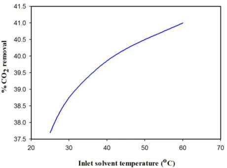
4.6. Effect of liquid temperature
The variation in solvent temperature affects the reaction rate constant and the solubility of the CO2 in solvent, as well. As a result, the change in
temperature is expected to cause significant impact on the rate of CO2
absorption. Figure 10 shows experimentally the effect of temperature on the CO2 percent removal. As can be seen, with increasing solvent temperature,
the CO2 removal rate also increases. This can be attributed to the fact that as
the temperature increases, the reaction rate increases due to increase in reaction rate constant and, consequently, more CO2 is absorbed. The physical
solubility decreases with temperature; meanwhile the chemical solubility increases with temperature, which leads to the increase in the percent of CO2
removal. A net enhancement of CO2 removal is also observed with increasing
temperature.
Fig. 10. Effect of solvent temperature on the percentage removal of CO2.
4.7. Effect of liquid flow rate
Figure 11 illustrates the experimental results for the variation of the percentage removal of CO2 as a function of liquid flow rate. As the absorbent
flow rate increases, the mass transfer rate of carbon dioxide into the liquid increases due to the concentration gradients of CO2 and absorbent in the
liquid increase. Thus the CO2 outlet concentration in gas decreases and the
percentage removal of CO2 increases [34]. The figure clearly indicates that
liquid flow rate in the flat sheet membrane has significant effect on the CO2
removal.
Fig. 11. Effect of inlet liquid flow rate on the percentage removal of CO2.
5. Conclusions
Flat sheet membranes offer moderate membrane surface/volume ratios compared to hollow fiber membranes. A mathematical model was developed to describe the transport of CO2 in a flat sheet membrane contactor using
aqueous NaOH as the absorbing agent. The model was established considers non-wetting condition for a countercurrent gas–liquid flow arrangement. The model was validated with experimental data. The model predictions and experimental data were in good agreement. The effect of solvent concentrations, gas and liquid flow rates, liquid temperature on the CO2
removal efficiency and removal flux were studied. The removal percentage of CO2 was found to increase with increasing the NaOH concentration. Both
liquid temperature and liquid flow rate encouraged the removal process. By contrast, gas flow rate can has a negative effect.
6. Nomenclature
A Total area of membrane, m2
i
C Concentration of component
i
; 1: CO2, 2: CH4, 3: NaOHm i
C, Concentration of component
i
in the membrane section, mol m-3g i
C, Concentration of component
i
in the gas section, mol m -3l i
C
, Concentration of componenti
in the liquid section, mol m-3
i
D Diffusion coefficient of component
i
: 1: CO2, 2: CH4, 3: NaOHL Length module, m W Module width, m
m
Physical solubilityGreek letters
Gas density, g cm-3
Viscosity of gas, Pa s
Membrane bulk porosity7. References
[1] N. Abdul Rahim, N. Ghasem, M. Al-Marzouqi, Absorption of CO2 from natural
gas using different amino acid salt solutions and regeneration using hollow fiber membrane contactors. J Nat. Gas Sci. Eng. 26 (2015) 108-117.
[2] N. Ghasem, M. Al-Marzouqi, Z. Ismail, Gas–liquid membrane contactor for ethylene/ethane separation by aqueous silver nitrate solution, Sep. Purif.
Technol. 127 (2014) 140–148.
[3] Y. Le Moullec, T. Neveux, A. Al Azki, A. Chikukwa, K. A. Hoff, K, Process modifications for solvent-based post-combustion CO2 capture. Int. J. Greenh.
Gas Con. 31 (2014) 96–112.
[4] S.M.R. Razavi, S.M.J Razavi, T. S. Miri, Shirazian, CFD simulation of CO2
capture from gas mixtures in nanoporous membranes by solution of 2-amino-2-methyl-1-propanol and piperazine. Int. J. Greenh. Gas Con. 15 (2013), 142–149. [5] S. Shirazian, S.N. Ashrafizadeh, Mass transfer simulation of carbon dioxide absorption in a hollow-fiber membrane contactor. Sep. Sci. Technol. 45 (2010), 515–524.
[6] S. Shirazian, A. Marjanm, F. Azizmohammadi, Prediction of SO2 transport
across ceramic membranes using finite element method (FEM). Orient. J. Chem. 27 (2011), 485–490.
[7] A. Gabelman, S.T., Huang, Hollow fiber membrane contactors. J. Membr. Sci. 159 (1999) 61–106.
[8] P. Luis, T. V. Gerven, B. V. der Bruggen, Recent developments in membrane-based technologies for CO2 capture, Prog. Energy Combust. Sci. 38 (2012)
419-448.
[9] N.M. Ghasem, M. Al-Marzouqi, A. Duaidar, Effect of quenching temperature on the performance of poly (vinylidene fluoride) microporous hollow fiber membranes fabricated via thermally induced phase separation technique on the removal of CO2 from CO2 - gas mixture, Int. J. Greenh. Gas Cont. 5 (2011)
1550–1558.
[10] P. Luis, B. V. der Bruggen, T. V. Gerven, Non-dispersive absorption for CO2
capture: from laboratory to industry, J. Chem. Technol. Biotechnol. 86 (2011) 769-775.
[11] Y.-S. Kim, S.-M. Yang, Absorption of carbon dioxide through hollow fiber membranes using various aqueous absorbents, Sep. Purif. Technol. 21 (2000) 101–109.
[12] V.Y. Dindore, D.W.F. Brilman, F.H. Geuzebroek, G.F. Versteeg, Membrane solvent selection for CO2 removal using membrane gas–liquid contactors, Sep.
Purif. Technol. 40 (2004) 133-145.
[13] E. Drioli, A. Criscuoli, E. Curcio, Membrane contactors: fundamentals, applications and potentialities, Vol. 11, Elsevier, DEC-2005.
[14] N. M. Ghasem, M. Al-Marzouqi, N. Abdul Rahim, Effect of polymer extrusion temperature on poly(vinylidene fluoride) hollow fiber membranes: Properties and performance used as gas–liquid membrane contactor for CO2 absorption,
Sep. Purif. Technol. 99 (2012) 91–103.
[15] N. M. Ghasem, M. Al-Marzouqi, L.P. Zhu, Preparation and properties of polyether sulfone hollow fiber membranes with o-xylene as a additive used in membrane contactors for CO2 absorption, Sep. Purif. Technol. 12 (2012) 1-10.
[16] S. Atchariyawut, R. Jiraratananon, R. Wang, Separation of CO2 from CH4 by
using gas–liquid membrane contacting process, J. Membr. Sci. 304 (2007) 163– 172.
[17] M. Hedayat, M. Soltanieh, S.A. Mousavi, Simultaneous separation of H2S and
CO2 from natural gas by hollow fiber membrane contactor using mixture of
alkanolamines, J. Membr. Sci. 377 (2011) 191–197.
[18] R. Wang, H.Y. Zhang, P.H.M. Feron, D.T. Liang, Influence of membrane wetting on CO2capture in microporous hollow fiber membrane contactors, Sep.
Purif. Technol. 46 (2005) 33–40.
[19] N. Abdul Rahim, N. Ghasem, M. Al-Marzouqi, Absorption of CO2 from natural
gas using different amino acid salt solutions and regeneration using hollow fiber membrane contactors. J Nat. Gas Sci. Eng. 26 (2015) 108-117.
[20] P. Luis, A. Garea, A. Irabien, Modeling of a hollow fiber ceramic contactor for SO2 absorption, Sep. Purif. Technol. 72 (2010) 174-179.
[21] S. Khaisri, D. deMontigny, P. Tontiwachwuthikul, R. Jiraratananon, A mathematical model for gas absorption membrane contactors that studies the effect of partially wetted membranes, J. Membr. Sci. 347 (2010) 228–239. [22] J.-G. Lu, Y.-F. Zheng, M.-D. Cheng, wetting mechanism in mass transfer
process of hydrophobic membrane gas absorption, J. Membr. Sci. 308 (2008) 180–190.
[23] S. Atchariyawut, R. Jiraratananon, R. Wang, Mass transfer study and modeling of gas–liquid membrane contacting process by multistage cascade model for CO2 absorption, Sep. Purif. Technol. 63 (2008) 15–22.
[24] K. Li, J. Kong, X. Tan, Design of hollow fiber membrane modules for soluble gas removal, Chem. Eng. Sci. 55 (2000) 5579–5588.
[25] M. Mavroudi, S.P. Kaldis, G.P. Sakellaropoulos, A study of mass transfer resistance in membrane gas–liquid contacting processes, J. Membr. Sci. 272 (2006) 103–115.
[26] Z. A. Tarsa1, S. Ali Asghar Hedayat1, M. Rahbari-Sisakht. Fabrication and characterization of polyetherimide hollow fiber membrane contactor for carbon dioxide stripping from monoethanolamine solution, J. Membr. Sci. Res. 1 (2015) 118-123.
[27] R.B. Bird, W.E. Stewart, E.N. Lightfoot, Transport phenomena, 2nd ed., Jonh
Wiley & Sons, Inc., New York, 2002.
[28] F.P. Incropera, D.P. DeWitt, T.L. Bergman, A.S. Lavine, Fundamentals of heat and mass transfer, 6th ed., New York, John Wiley & Sons, 2007.
[29] N.N. Li, A.G. Fane, W.S.W. Ho, T. Matsuura (Eds.), Advanced membrane technology and applications, John Wiley & Sons Inc., New York, USA, 2008. [30] Z. Qi, E.L. Cussler, Microporous hollow fibers for gas absorption. Part 1: mass
transfer in the liquid, J. Membr. Sci. 23 (1985) 321–332.
[31] G.F. Versteeg, W.P.M. van Swaaij, Solubility and diffusivity of acid gases (CO2, N2O) in aqueous alkanolamine solutions, J. Chem. Eng. Data 33 (1988)
29-34.