©2012 JNAS Journal-2012-1-4/121-127 ISSN 0000-0000 ©2012 JNAS
Application of Active Power Filters to compensate reactive power
Masoud Sabaghi
Department of electrical Engineering, Ashtian Branch, Islamic Azad University, Ashtian, Iran
Corresponding author Email : shayanfarahani@yahoo.com
ABSTRACT: Active power filters (APFs) play an important role in elimination of power system harmonics. According to these structures, they can be used to compensate of network reactive power. In this paper, reactive power compensation along with removing of network harmonics by APF has been studied. For this purpose, an active power filter has been simulated using hysteresis current control (HCC) method in the PSIM software. Simulations have been accomplished for different operation modes such as harmonics elimination, reactive power compensation and instantaneously harmonics elimination along with reactive power compensation. Obtained results have shown that by a suitable planning of APFs can be used their capabilities in the reactive power compensation application.
Keywords: Active power filter, harmonic compensation, reactive power compensation and AC/DC converter.
.
INTRODUCTION
The growing number of power electronics-based equipment has produced an important impact on the quality of electric power supply. Nonlinear load such as AC/DC converter, arc furnace, switching power supplies have been significantly growth in the power system and smart grid. These kinds of loads may inject harmonic current into the power system; leading to distort network voltage and also to increase total losses of network (Chang and Chang JULY 2000). Passive filters are the first solution to eliminate these harmonics, however; they have demerits of fixed compensation, large size, and resonance (harmonic amplification can be occurred). Alternatively, the active filters are used to eliminate the power system harmonics to the range of harmonic standards such as IEEE-519 (Singh and Al-Haddad Oct. 1999).
Active power filters, have been widely used to suppress harmonics of network. In fact the APF injects harmonic current to point of common coupling (PCC) equal but opposite with harmonic current of the nonlinear load in order to neutralize PCC harmonic current.
122
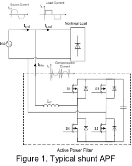
power filter that is shown in Fig. 1. The APF can operate in both rectifying (rectifier) and inversion (inverter) modes. A dead band with an upper and lower boundary current reference is used to generate the switching signals. The output current is regulated by comparing actual current with a reference current and the difference between the two current (∆I) is used to turn on or off the switch. Regardless of where the current starts, switching takes place as soon as a boundary is encountered. Initially, in Fig. 1, the switches S1 and S2 are turns on and S3 and S4 are turns
off because the output current of the AC/DC converter is below the lower (turn-on) boundary. The output current then rises at a rate limited only by the inductor, the capacitor, and the load. The switches S1 and S2 then turn off
and S3, and S4 are turns on. When the output current crosses the upper boundary and it remains off until the output
current falls below and cross the lower boundary where the switch is turned on again. The variation of switch S1 is
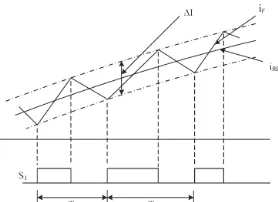
shown in Fig. 2.
Figure 1. Typical shunt APF
Hysteresis control in principle eliminates the output variations and the system will stay close to the desired output current even if the input voltage, the load, or the component values change. Hysteresis control also provides an immediate response to dynamic disturbances. The control circuit is very simple and relatively straightforward to design and physically implement.
In this method, output current between two upper and lower band current is varied. In fact, the output current should be between two sinusoidal currents. In this method, hysteresis band is remained fixed. According to Fig. 2, the following equation can be written:
) t sin( . I
Iref m (1)
2
I I Iref,up ref
(2)
2
I I Iref,down ref
(3)
Where, ∆I is hysteresis bandwidth. The point, which should be mentioned in this way, is that according to Fig.2, switching frequency is changeable. Moreover, this and this matter should be taken into consideration in switches selection and loss calculation. In other words, by increasing hysteresis bandwidth, switching frequency decreases.
S1
S4 S3
S2 Grid
Nonlinear Load
Igrid ILoad
Ifilter
LC
123
Figure 1. Filter current control with Hysteresis control method
Active Filter Operation modes
An active filter due to using semiconductor technology in its structure have many capabilities. For instance, if an active filter is connected to an energy source or a battery in DC link, it can transfer battery energy to network. Hence four operating modes are considered which are as:
Mode 1: active power injection
Mode 2: reactive power injection
Mode 3: distortion power injection (harmonic cancelation)
Mode 4: instantaneously active, reactive power injection and harmonic cancelation
Operation of each mode will be explained. It should be mentioned that network voltage is expressed as following equation:
) t sin( . V
Vgrid m (4)
Mode 1: Active power injection
In this mode, sinusoidal reference current is considered in phase a network voltage and active current is injected to the network. In this mode, reference current is considered according to this equation:
) t sin( . I
Iref m (5)
Mode 2: Reactive power injection
One of the network requirements is reactive power. Providing locally reactive power has some advantages such as voltage profile improvement, loss reduction and so on. Therefore, if active power filter is used in reactive power injection mode, we can benefit advantage of locally providing reactive power. In this case, the reference current similar to mode 1 is considered sinusoidal. But it is not in phase with network voltage. Reference current is considered as:
) t sin( . I
Iref m
(6)
Where “+” is for capacitive reactive power and “–“ is for inductive reactive power.
Mode 3: Harmonic cancelation
The main duty of active power filters is elimination of network harmonic. In this mode, active filter provides current harmonic component requirement for load current and it presents harmonic current absorption from network. In this case, reference current is equal to sum of harmonic components requirement for load. Hence, load current harmonic component should be identified and they should be produced by active filter. Reference current in this case is:
N
n
n n
, m
ref I sin(n t )
I 2
(7)
Where N is the highest order load current harmonics and Im,nis amplitude of nth component of load current.
However, some of these components amplitudes may be zero. Therefore, in this case this component will not be produced by active filter.
Mode 4: Instantaneously active, reactive power injection and harmonic cancelation
124
Simulation result
The filter parameters are shown in Table 1. To investigate the efficiency of active power filter in the harmonic cancelation, reactive power compensation and injecting of active power to network, a sample active filter according to Fig. 3 is simulated by PSIM, which obtained results are investigated. It is noted that the simulation has been done for all of four operation modes of active filter, which is described in section 4.
Table 1. Filter parameters parameter value
Vgrid 220
R1 10 kΩ
R2 1 kΩ
Rf 20 kΩ
LC 7 mH
In 10 A
Figure 3. Modeling of Filter with hysteresis current control in PSIM
Mode 1: Active power injection
In this operating mode, reference current is considered as: )
t sin(
.
Iref10 250
(9)
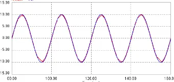
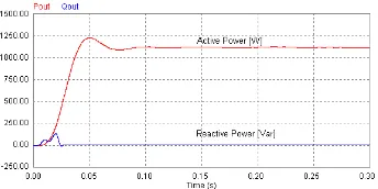
Reference current and output current waveforms in this case are shown in Fig. 4. According to this figure, injecting current follows reference current well and injects active power to network. Instantaneously active and reactive power is shown in Fig. 5. In this mode, only active power is injected to the network. As a result, reactive power is equal to zero.
Figure 4. Filter output current and reference current in the active power injection mode
Hysteresis Current Control
125
Figure 5. Active and Reactive power injected to grid in the active power injection mode
Mode 2: Reactive power injection
Reference current for mode 2 is considered as: )
/ t sin( .
Iref10 250 2 (10)
The reference current and output current for this mode are illustrated in Fig. 6. It is also viewed from this figure that injected reactive current follows reference current well.
Figure 6. Filter output current and reference current in the reactive power injection mode
Instantaneously active and reactive power is shown in Fig. 7. According to this figure, active power is equal to zero and reactive power is very high in comparison with reactive power. In this case, regarding the φ1 difference,
active current can be also injected to the network. For this purpose, φ1 should be less than 90. In Fig. 8, filter
current and network voltage are shown. To better observation, current is 10 times higher and φ1 =π/4.
Figure 7. Active and Reactive power injected to grid in the reactive power injection mode with φ1=π/2
Figure 8. Filter output current and reference current in the active and reactive power injection mode
Instantaneously active and reactive power for φ1 =π/4 and injected active and reactive power to network by
filter is shown in Fig. 9, active and reactive power are respectively equal to 735 W and -811 Var. Regarding φ1=π/4,
126
Figure 9. Active and Reactive power injected to grid in the active and reactive power injection mode with φ1=π/4
Mode 3: Harmonic power injection
The content harmonics in power systems are orders of 6k±1, k=1, 2, 3,… so, in this operating mode the reference current is considered as:
) t sin( . ) t sin( . ) t sin( . ) t sin( . ) t sin( . ) t sin( . ) t sin( . ) t sin( . Iref 25 345 0 23 408 0 19 45 0 17 564 0 13 645 0 11 904 0 7 12 1 5 26 2 (11)
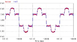
Reference current and output current are shown in Fig. 10. According to this figure, injected harmonic current follows reference current properly. In this case, active and reactive power is not injected to the network because fundamental component of current does not exist in the reference current.
Figure 10. Filter output current and reference current in the harmonic cancelation mode
Mode 4: instantaneously injection of active, reactive and harmonic power
In this case, all three active, reactive and distortion power can be injected to the network. Reference current is considered as: ) t sin( . ) t sin( . ) t sin( . ) t sin( . ) t sin( . ) t sin( . ) t sin( . ) t sin( . ) t sin( Iref 25 345 0 23 408 0 19 45 0 17 564 0 13 645 0 11 904 0 7 12 1 5 26 2 30 10 (12)
In this mode, the output current is shown in Fig. 11. According to this figure, output current follows the reference current well.
Figure 11. Filter output current and reference current in the harmonic cancelation with active and reactive power injection to grid mode
CONCULSION
127
instantaneously injection of active, reactive and distortion power to network in order to eliminate the harmonics which can be obtained by selection of a suitable reference current.
REFERENCES
Afonso, J. L., M. J. S. Freitas, et al. (2003). "p-q Theory power components calculations " Industrial Electronics, 2003. ISIE '03. 2003 IEEE International Symposium on 385 - 390.
Aredes, M., J. Hafner, et al. (1997). "Three-phase four-wire shunt active filter control strategies " IEEE Transactions on Power Electronics 12(2): 311 - 318.
Chang, T. T. and H. C. Chang (JULY 2000). "An Efficient Approach for Reducing Harmonic Voltage Distortion in Distribution Systems with Active Power Line Conditioners." IEEE TRANSACTIONS ON POWER DELIVERY 15(3).
Fujita, H. and H. Akagi (1991). "A practical approach to harmonic compensation in power systems-series connection of passive and active filters " IEEE Transactions on Industry Applications 27(6): 1020 - 1025.
Kim, S. and P. N. Enjeti (2002). "A new hybrid active power filter (APF) topology." IEEE Transactions on Power Electronics 17(1): 48-54.
Kim, Y. S., J. S. Kim, et al. (2004). "Three-phase three-wire series active power filter, which compensates for harmonics and reactive power " IEE Proceedings -Electric Power Applications, 151(3): 276 - 282.
Komatsu, Y. and T. Kawabata (1997). "Characteristics of three phase active power filter using extension pq theory " Industrial Electronics, 1997. ISIE '97., Proceedings of the IEEE International Symposium on 302 - 307.
Li, H., F. Zhuo, et al. (2004). "A novel current detection algorithm for shunt active power filters in harmonic elimination, reactive power compensation and three-phase balancing " Power Electronics Specialists Conference, 2004. PESC 04. 2004 IEEE 35th Annual 2: 1017 - 1023.
Lin, B. R. and Y. C. Lee (2004). "Three-phase power quality compensator under the unbalanced sources and nonlinear loads " IEEE Transactions on Industrial Electronics 51(5): 1009 - 1017.
Miret, J., L. G. DeVicuna, et al. (2004). "A simple sliding mode control of an active power filter." Power Electronics Specialists Conference, 2004. PESC 04. 2004 IEEE 35th Annual 2: 1052 - 1056.
Singh, B. and K. Al-Haddad (Oct. 1999). "A review of active filters for power quality improvement." IEEE Trans. Ind. Electron 46(5): 960-971.
Singh, B., K. Al-Haddad, et al. (1998). "A new control approach to three-phase active filter for harmonics and reactive power compensation " IEEE Transactions on Power Systems 13(1): 133 - 138.
Sladic, S., M. Odavic, et al. (2004). "Single phase active power filter " Electrotechnical Conference, 2004. MELECON 2004. Proceedings of the 12th IEEE Mediterranean 3.
Sonnenschein, M. and V. Staudt (1998). "Evaluation of a shunt active filter using frequency identification " Harmonics and Quality of Power Proceedings, 1998. Proceedings. 8th International Conference On 2: 617 - 622.
Takeda, M., K. Ikeda, et al. (1988). "Harmonic current and reactive power compensation with an active filter " Power Electronics Specialists Conference, 1988. PESC '88 Record., 19th Annual IEEE: 1174 - 1179.