RESEARCH ARTICLE
An experimental study on surface state
description by wiping motion for the estimation
of floor surface condition using indoor search
robot
Koichiro Matsumoto
1*and Kimitoshi Yamazaki
2Abstract
In this paper, we aimed to establish a novel method for surface condition measurement for the indoor floor. To meas-ure the surface condition, we proposed wiping motion that to stroke the target surface with changing the stroking speed. We developed the wiping device with a 6-axis force sensor, a passive pivot, and a contact plate to realize the wiping motion. In the experiment, the surface condition was measured using four kinds of floor materials and two kinds of liquids. From the experimental results, it was confirmed that the resistance force depends on the wiping velocity. From the experimental results, we confirmed the effectiveness of the proposed method and examined the quantitative index used for surface state description.
Keywords: Surface condition, Wiping motion, Dynamic frictional force, Floor reaction force, 23rd Robotics Symposia
© The Author(s) 2018. This article is distributed under the terms of the Creative Commons Attribution 4.0 International License (http://creat iveco mmons .org/licen ses/by/4.0/), which permits unrestricted use, distribution, and reproduction in any medium, provided you give appropriate credit to the original author(s) and the source, provide a link to the Creative Commons license, and indicate if changes were made.
Background
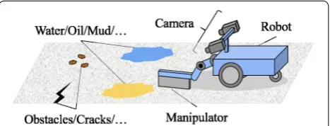
It is needed to investigate damaged building such as a factory or a plant, but it is dangerous for the people to walk-in there. So, it is better to investigate such an envi-ronment using a teleoperated robot. The operator who is in the safe place will know the environmental informa-tion through the robot and will become able to steer the robot for investigation or object manipulation.
Tasks expected for such a robot are a movement to places where human is hard to arrive, and operation of objects. To carry out these tasks, it is needed to know the spatial information like the coordinate or the map, and the object information like the rubbles or the doorknob.
For the previous study, Ohno et al. [1] made a dense 3D map of a disaster-affected environment by using a camera and laser scanner. Development of robots that manipulate valves, doorknobs, etc., has been studied [2]. They developed the manipulator with the camera on
it’s behind of end-effector. With this system, the opera-tor can manipulate the door with the visual information which was transmitted by the robot.
However, in those studies remains some issues to solve. In those research premised that the surface that the robot will traverse or of the object to manipulate is not con-taminated by oil or water. In a damaged building such as a factory, it is conceivable that a high-viscosity liquid such as oil or a powder of fine particle size such as dust is scattered on the floor. When the robot traverses such a region, liquid or powder adheres to the contact area. For example, when a wheel type mobile robot enters an oil sump, oil adheres to the wheel. With such a state, if operator makes the robot to try to move quickly or make a sudden turn, it will cause slipping and falling. This can lead to failure or damage of self position estimation. Therefore, by measuring the surface condition and pre-senting the information to the pilot who is in a remote place, it would be possible to adopt advance measures such as avoiding that route, which would lead to failure avoidance.
The purpose of this study is to establish a novel method to measure the surface condition of the floor. We propose
Open Access
*Correspondence: [email protected]
1 Interdisciplinary Graduate School of Science and Technology, Shinshu
University, 4-17-1, Wakasato, Nagano, Nagano, Japan
a mechanism that can quantitatively estimate differences in flooring materials, the presence of liquids, the proper-ties of liquids, etc.
We use the contact measurement for surface condi-tion measurement. In contact measurement, it can be proposed a method by using a robot with a sensor that can measure the frictional force on contact as shown in Fig. 1. The contact measurement has the advantage to obtain surface information like surface hardness, slip-periness, and shape in compared with the non-contact measurement. In this study, we propose a method of con-tact measurement called wiping motion. Wiping motion is the motion that sweeps on the surface with using a part of the robot body. By changing wiping condition, the resistance force from the surface can be changed, and will make it possible to obtain the information of surface state.
The contributions of this study are described in below. Proposal of the wiping motion:
We proposed a simple method of surface condition measurement. Floor materials and sediments can be detected from the frictional force and floor reaction force when the target surface is wiped off.
Device development for wiping motion:
We developed the simple and robust wiping device consist of a force sensor, a passive joint, and a contact plate.
Investigation of surface state description:
We examined the possibility of describing the surface condition. We used the relationship between resistance force obtained from friction force and floor reaction force and floor material hardness and liquid viscosity.
Related works
Surface condition estimation has been studied by using many kinds of device and methods. Anelia et al. [3] made a study to predict slippery areas based on visual informa-tion obtained from the camera and the past slip infor-mation. For measuring the slip, the difference between
the body speed and the rotation speed of the tire was used. This method is a simple and effective on wheel type mobile robot. However, it can be said that it is the measurement method which depends on moving form of robot. So it is not the general method for surface condi-tion measurement. It is needed to propose novel meas-urement method that not depend on robot’s moving form.
Regarding of the studies about the identification of surface and estimation of friction force, literature [4–6] can be mentioned. In these studies, the static friction forces of various road surfaces are measured in advance by using spring balances, and the road surface type and the frictional force are estimated by judging the road sur-face from the image appearance and image features in the region. In the study of Martim et al. they pointed out that it is important to accurately estimate the material of the surface for estimation of frictional force. The material used for the floor can be sufficiently different material even though it has the same appearance. For this reason, there is room for further study in considering evaluation indices that are different from indices based on image information for every floor material.
In this paper, we propose a relatively general surface state measurement method independent of the robot movement form. In addition, we compare the measured value with the physical properties of the object and inves-tigate the quantitative index used for the surface state description.
Methods Problem settings
We consider a situation where human can not enter because buildings are damaged by disasters and toxic gases are generated in the building. In such situation, we will consider investigating by using a teleoperated robot. The robot chooses and moves the surface where flat-ness remains as much as possible as a path which stick-ing or fallstick-ing will hardly occur. In this study, we consider a method to clarify the hardness of the flat floor surface, the slipperiness, and the presence of liquid.
Wiping motion
vibration is called Stick-slip, and it will appear when the system is unstable.
The frictional force will be changed depending on surface slipperiness, and the floor reaction force will be changed depending on the surface hardness of the floor. This means that the information of surface hardness and slipperiness for surface description can be acquired by measuring the frictional force and floor reaction force.
The purpose of this study is to make it possible to describe the surface condition of floor surface by quan-titative index. As mentioned above, floor reaction force and frictional force will be changed by surface hardness and surface slipperiness. So, we take the approach that utilizes the resultant force of them as the resistance force. However, with this approach, it is difficult to identify the different condition surface that indicates same resistance force. Therefore, we consider wiping motion by chang-ing the velocity of wipchang-ing (we call it wiping velocity). This motion is based on the idea that the floor reaction force and the dynamic frictional force will change depending on the velocity of rubbing [7].
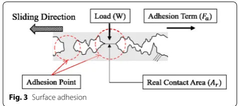
The friction force Ff which is now generally understood is a theory that it consists of the adhesion term Fa and the
digging term Fd . Comparing the adhesion term and the
digging term, the influence of digging term is tiny, so the frictional force is approximated by the adhesion term as follows.
Regarding this adhesion term, a conceptual diagram is shown in Fig. 3. The two surfaces to be contacted are not perfectly smooth, and are in contact with each other by the fine projections with high load. The protruding por-tion adheres due to this load. The fricpor-tional force is con-sidered to be the main cause of the shearing force of this adhesion part. The adhesion point is thought to grow as the contact time of the surface is longer, so the friction coefficient is thought to be a function depending on the sliding speed.
(1) Ff =Fa+Fd ≃Fa
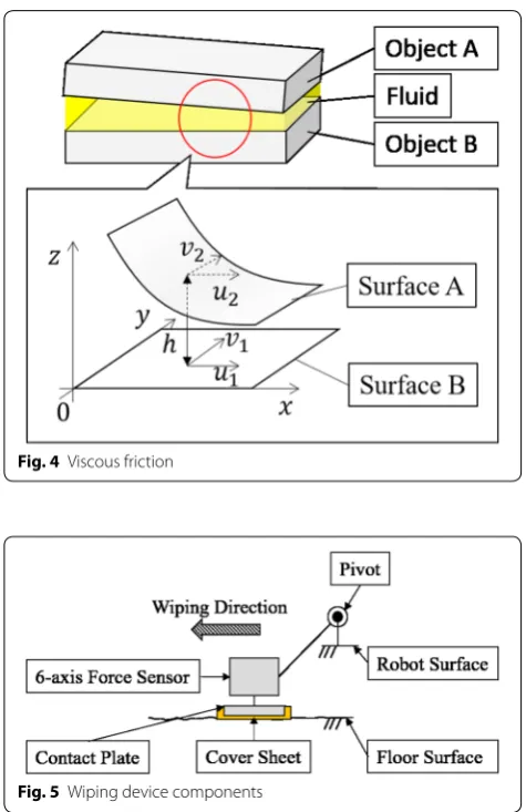
Figure 4 shows a conceptual diagram of viscous fric-tion when liquid is present between two faces. Consider-ing the case where there are relative slippage in the two faces in the figure, the frictional force generated by the fluid can be obtained from the Reynolds equation. Fric-tion forces Fx , Fy applied in the x axis direction and y axis
direction are shown below.
η is the average viscosity of fluid, h is the distance
between two planes, ui , vi ( i=1, 2) are the flow velocity
of the x axis and y axis direction, and the p correspond to the pressure. Since the flow velocity ui , vi in the equation
depends on the sliding velocity of the surface, it can be said that viscous friction is a function dependent on the sliding velocity.
Based on the above, it is predicted that resistance force, which is the resultant force of frictional force and floor reaction force, changes variously depending on the wip-ing velocity.
Wiping device components
The wiping device needs to be simple and robustness design because it will be assumed to use in disaster scenes. Therefore, we need to develop it without elabo-rate sensor or exquisite mechanism to acquire the resist-ance force. For that design, it is effective to avoid direct contact of the object surface and sensor. This makes it possible to avoid breakage and contamination of the sensor itself. In other words, it is necessary to interpose some components between the sensor and the target sur-face, which may degrade the quality of the sensor data.
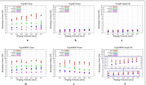
Based on the above, we propose a wiping device with the configuration as shown in Fig. 5. The main com-ponents of this device are a 6-axis force sensor, a pas-sive pivot, a contact plate, and a plate cover. The pivot reduces the influence of a slight level difference or
(2) Fx|z=h
0 =
η(u1−u2)
h ∓ h 2 dp dx dxdy (3) Fy|z=h
0 =
η(v1−v2)
h ∓ h 2 dp dy dxdy
Fig. 2 Force components of wiping motion
irregularities on the floor surface. The contact plate is a part to be grounded so as to be parallel to the floor sur-face. For obtain stable frictional force measurement, the bottom surface of the plate have a certain area. The plate cover is a part that directly touches the floor sur-face. Also, the cover needs to be a removable fitted thin plate. The cover to be removable, the measurement can be continued when contaminated the cover. By making the cover removable, it is not necessary to interrupt the
measurement even if liquid or the like adheres due to the wiping motion. The cover may be disposable, there is also a usage such as tentatively attaching the used cover to the body of the robot and taking it back and analyzing the adheres.
In creating the wiping device, there are several fac-tors to consider. The frictional force expressing the slip-periness varies depending on the magnitude of the load on the floor surface. This load varies depending on the attachment position of the sensor and the weight of the device. Also, the contact plate is better to have a smooth and hard surface. If the surface of contact plate is rough, the contact area between the target surface and the device will decrease. And, if the hardness of the con-tact plate cover is too soft, it will be assumed that wear is caused by the wiping motion, and repeat measure-ment becomes difficult. Besides wear, self-excited vibra-tion tends to occur because the system becomes unstable if the plate cover is soft. If we want to pay attention to the resistance force, this vibration is undesirable as it can hinder stable contact with the ground. For these reasons, it is desired that the plate cover is hard and smooth.
Result and discussion
Trial production for wiping device
Using the elements mentioned in the previous section, we prepared a wiping device of five different shapes. The schematic is shown in Fig. 6, and features of each shape are described below.
Type A: The rotating shaft position is high, and the contacting surface and the rotating shaft are separated. An aluminum plate with a thick-ness of 2 mm is added between the force sen-sor and the ground plate. The angle between the aluminum plate and the ground is an acute angle.
Type B: It is attached to a horizontally extended frame from the front edge of the robot, and the angle made by the aluminum plate and the ground is close to a right angle.
Fig. 4 Viscous friction
Fig. 5 Wiping device components
Type C: The rotation axis position is attached near the ground, and the angle made by the aluminum plate and the ground is obtuse.
Type D400: A shape in which an aluminum plate is eliminated and a force sensor is directly attached to a contact plate. It carries 400 g of weight.
Type D800: It is the same shape as Type D400, with a weight of 800 g installed.
In Type A to C, the force sensor and the contact plate were connected via an aluminum plate. When a wiping motion is performed, a resistance force is applied to the contact plate, and the resistance is measured by the sensor by bending the metal plate. In these three types, the angle the aluminum plate makes with the ground and the posi-tion of the rotary shaft are different. Due to this difference, the direction of the tangential force around the rotation axis of the contact plate is different, and the load applied to the ground at the time of executing the wiping motion is different. In Type A and Type C, the angle between the ground and the metal plate is an acute angle, obtuse angle respectively. By doing like this, we expected that the amount of deflection of the metal plate can be made smaller than the right angle, and unnecessary force witch is the cause of stick-slip vibration will not be applied.
In Type D, an arbitrary weight can be mounted instead of a aluminum plate. It is possible to adjust the load applied to the ground by the weight.
Experimental settings
The experiment has occurred that verification effectiveness for quantitative description of a surface condition by wip-ing motion. For the first, four kinds of floorwip-ing materials which have different physical property have selected. Liq-uids having different viscosities such as water and oil were selected, and they were thinly applied to each floor materi-als. The wiping device was installed the front part of wheel type mobile robot and collected force data when the robot moves forward. The floor material which we use in this experiment was selected often used indoors. The selected floor materials are shown in Fig. 7, are PVC sheet (PVC), linoleum (Linoleum), acrylic board (Acrylic) and stainless board (Stainless). In the Table 1, there is the surface hard-ness of each floor materials, measured by Scratch hardhard-ness test (Pencil method), which is defined in JIS K5600-5-4. The liquids which we used in this experiment are water, salad oil. In Table 2, the viscosity of each liquids was described. The regions to coat these liquids were the width of the con-tact plate and the surface by wiping motion. This means the liquid will not affect the robot’s wheel. The contact plate was made by ABS resin. Its shape is shown in Fig. 8. It is a shape having a curved surface on the bottom surface, the
front surface, and the rear surface of the rectangular paral-lelepiped. A stainless steel cover with a thickness of 0.2 mm was attached as a hard and smooth material.
Experiment of surface condition measurement
For each flooring material, the surface condition meas-urement using the wiping motion was performed. The state of each flooring material was set to the following three states, and the resistance force in each state was measured.
• Clean: The surface condition without liquid
• Water: The surface is covered with water
• Salad oil: The surface is covered with salad oil
With regard to the wiping velocity, the moving speed of the robot was changed from 0.1 to 0.7 m/s in increments of 0.1 m/s.
Comparison of measurement results
Figure 9 is the measurement result of each device in Clean. The graph is drawn with a box-whisker plot, with the horizontal axis representing the wiping velocity and the vertical axis representing the resistance force. Each resistance values in the result are the median value at that wiping velocity. The magnitude of the resistance force Fr
is obtained from the load on the sensor’s Fx , Fz direction
shown in Fig. 6 by the following formula.
Type A resulted in a decrease in resistance in PVC floor-ing with increasfloor-ing wipfloor-ing velocity. From these results, resistance force increased with velocity increasing in four kinds of devices except Type A. Therefore, the wiping device needed to select from among four types of Type B to Type D800.
(4)
Fr =
F2 x +Fz2
The results among Type B to Type D800 can be sepa-rated into two groups: (I) Resistance is clearly different for each flooring material, (II) There is little difference in resistance force. Type B and Type D800 belong to the group (I), and Type C and Type D400 belong to the group (II). This difference occurs because of the difference in load applied to the floor. It can be said that (I) is the suita-ble wiping device because the difference in surface condi-tion does not appear in resistance force in the group (II).
The floor surface to which water or salad oil was applied was subjected to wiping motion and the resistance force was measured with the device of the group (I). Figure 10 shows the result of resistance force when applied wiping motion on the floor coated with liquid by using Type B and Type D800. These graphs labels are same as Fig. 9. Compare the result with Type B and Type D800 of Water, the Type B result has a very small difference of resistance force in each floor materials. From these results, Type D800 is the suitable for wiping motion.
Consideration of surface state description
Summarize the results of Type D800 shown in Fig. 10d–f.
Clean: Increasing trend with respect to wiping velocity. Softer flooring material has higher resistance.
Table 1 Floor materials list
Name Pencil hardness Surface roughness [ µm]
PVC 5B 4.855
Linoleum 2B 1.79
Acrylic 4H 1.565
Stainless Over 6H 1.67
Table 2 Liquids list
Name Viscosity [mPa·s]
Water 1.0
Salad oil 52.5
Fig. 8 Sectional view of contact plate
Water: Decrease tendency with respect to wiping velocity. Softer flooring material has higher resistance.
Salad oil: Increasing trend with respect to wiping veloc-ity. Regardless of the hardness of the flooring material, the resistance force is almost the same value.
Here, using the result obtained from Type D800, the magnitude of the hardness of the floor material is com-pared with the magnitude of the resistance force. Fig-ure 11 is a graph obtained by taking the hardness of the flooring material on the horizontal axis and the resist-ance force on the vertical axis. It is understood from this graph that the harder the hardness of the flooring mate-rial is, the smaller the resistance value becomes regard-less of the surface slipperiness. That is, in surface state measurement, the information on the hardness can be represented by the magnitude of the resistance force.
From the results of previous experiments, the following were found about the hardness and the slipperiness of the flooring materials expressing the surface condition.
Hardness of floor: It is related to the magni-tude of resistance force. The
greater the resistance, the lower the resistance, the harder it becomes.
Slipperiness: It appears as a tendency of resistance to wiping velocity. It appears as a ten-dency of resistance to wiping velocity.
Fig. 10 Resistance force deference. a Type B clean, b Type B water, c Type B salad oil, d Type D800 clean, e Type D800 water, f Type D800 salad oil
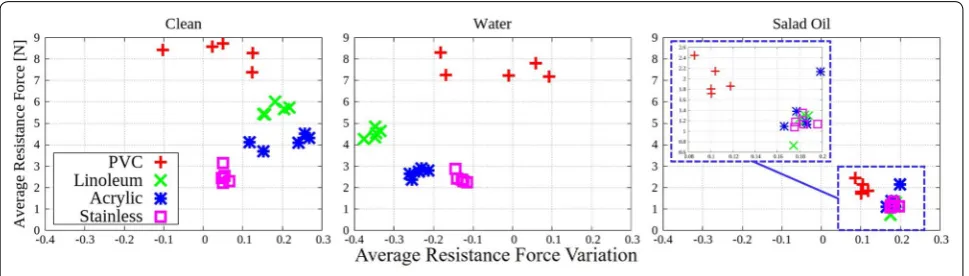
From this result, we propose average resistance force value and average resistance force variation as the fea-ture quantity for surface state description. The average resistance force value ( Ravg ) is the average value of the
resistance value at each wiping velocity, as represented by the following expression (5). The average resistance force variation ( Vavg ) is the average value of resistance
change amount for each change in wiping velocity and is expressed by the following Eq. (6).
Fvi in the formula means the median of resistance at each
wiping velocity vi , and N means the kind of wiping
veloc-ity. (In this case, N=7, since wiping velocity was set to 0.1–0.7 m/s.)
Figure 12 shows the above index of the result of Type D800. In this graph, the average resistance force variation is plotted on the horizontal axis and the average resist-ance value is taken on the vertical axis.
Each marker refers to each floor material. As can be seen from this results, in the three states of Clean, Water, Salad oil, markers are present in each area that is grouped for each floor material. This means that the variation of data is small for each trial of the wip-ing motion. At the same time, the existence position of the marker strongly depends on the surface condition. These results suggest that the index of average resist-ance force variation and average resistance force value is an index that works effectively in feature quantity description.
(5) Ravg =
1
N N
i=1 fvi
(6) Vavg =
1
N−1
N−1
i=1
(fvi+1−fvi)
Conclusion
In this paper, we proposed a wiping motion that makes it possible to measure the surface condition as sur-face hardness and slipperiness. Experiments showed that wiping motion works effectively for surface state measurement, and proposed an index for surface state description.
We will summarize what we predicted in this paper and what we found through experiments below.
What we predicted in this paper:
1. The surface condition can be measured from the resistance force generated by wiping motion
2. The resistance force depends on the wiping velocity, since the dynamic frictional force and the floor reac-tion force, components of the force, are dependent on the rubbing speed
3. The wiping device can be configurable with simple design consist of the multi-axis force sensor and the passive pivot
Things found by experiment:
1. Possibility to measure surface condition by wiping motion
2. The resistance force changes depending on the wip-ing velocity, the surface hardness of the floor, and the kind the liquid applied to the floor
3. The lower the surface hardness, the higher the resist-ance force
4. The suitable shape for the wiping motion is the shape doesn’t have aluminum plate like Type D.
information of measurement data, and investigation about data dependence of robot posture are also future works.
Authors’ contributions
All authors equally contributed to develop the method. KM conducted device development, the experiments, analyzed data and wrote the manuscript. KY devised the proposed method. KY supervised the research. Both authors read and approved the final manuscript.
Author details
1 Interdisciplinary Graduate School of Science and Technology, Shinshu
University, 4-17-1, Wakasato, Nagano, Nagano, Japan. 2 Mechanical Systems
Engineering, The Faculty of Engineering, Shinshu University, 4-17-1, Wakasato, Nagano, Nagano, Japan.
Acknowledgements
This study has been done as the part of the research program ImPACT: tough robotics challenge.
Competing interests
The authors declare that they have no competing interests.
Ethics approval and consent to participate Not applicable.
Publisher’s Note
Springer Nature remains neutral with regard to jurisdictional claims in pub-lished maps and institutional affiliations.
Received: 31 January 2018 Accepted: 18 May 2018
References
1. Ohno K, Takenaka E, Nagatani K, Tadokoro S, Koyanagi E, Yoshida T (2011) 3-D shape measurement of disaster environment using remote-con-trolled tracked vehicle with laser scanner. IPSJ SIG-Comput Vision Image Media CVIM 2011(176):1–8 (domestic)
2. Toda K, Yamamoto H, Shimizu M, Kodachi T, Yoshida T, Nishimura T, Furuta T (2014) Camera arm system for disaster response robots (2nd report: a collision protection mechanism for real-world missions). In: The 3rd inter-national conference on design engineering and science (ICDES2014), pp 80–85
3. Angelova A, Matthies LH, Helmick DM, Perona P (2007) Learning and pre-diction of slip from visual information. J Field Robot Special Issue Space Robot 24(3):205–231
4. Goto T, Tamura H (2011) Estimation system of coefficient of friction by photo image for mobile robot. Forum Inf Technol 10(3):301–304 (domestic)
5. Tamura H, Kambayashi Y (2016) Estimation of coefficient of static friction of surface by analyzing photo images. Intell Decis Technol 2016(57):15–26
6. Brandao M, Hashimoto K, Takanishi A (2016) Friction from vision: a study of algorithmic and human performance with consequences for robot perception and teleoperation. In: 2016 IEEE-RAS international conference on humanoid robots