RESEARCH ARTICLE
Force sensor utilizing stiffness
change of shape-memory polymer based
on temperature
Kazuto Takashima
1*, Hiroki Kamizono
1, Makoto Takenaka
1,2and Toshiharu Mukai
3Abstract
In this study, we propose a force sensor using a shape-memory polymer (SMP) whose stiffness varies according to the temperature. An SMP can be deformed above its glass transition temperature (Tg) by applying a small load. A deformed SMP maintains its shape when cooled below Tg and returns to its predefined shape when subsequently heated above Tg. The reversible change in the elastic modulus between the glassy and rubbery states of an SMP can be on the order of several hundred-fold. The relationship between the applied force and the deformation of the SMP changes depending on the temperature. Our sensor consists of strain gauges bonded to an SMP bending beam and senses the applied force by measuring the strain. Therefore, the force measuring range and the sensitivity can be changed according to the temperature. In this study, we evaluate a prototype of the sensor using the SMP sheet with embedded electrical heating wire. Moreover, we improve the sensor by combining the SMP and a stainless steel plate. The enhanced versatility of SMP force sensors is demonstrated through a series of experiments conducted using the prototype.
Keywords: Shape-memory polymer, Force sensor, Glass transition temperature, Cantilever, Strain gauge
© The Author(s) 2017. This article is distributed under the terms of the Creative Commons Attribution 4.0 International License (http://creativecommons.org/licenses/by/4.0/), which permits unrestricted use, distribution, and reproduction in any medium, provided you give appropriate credit to the original author(s) and the source, provide a link to the Creative Commons license, and indicate if changes were made.
Background
In today’s rapidly aging societies, robotic technology has been applied to various fields including industrial as well as nursing and welfare. For example, several power-assist suits and power assist apparatus have been proposed as wearable robots for caregivers and rehabilitation systems [1]. In these applications, it is necessary to measure a wide range of forces to grasp and lift various objects in the various operating environment accurately [1]. Previ-ously, for example, a wide-range and sensitive force sen-sor using a quartz crystal resonator was proposed [2]. Unlike this research, the characteristic of our proposed sensor is the utilization of the stiffness change of the material based on the temperature. To our knowledge, the stiffness change of the material has not yet been uti-lized for wide-range and sensitive force sensors. In the
present study, we exploit the inherent advantageous properties of shape-memory polymers (SMPs) [3–18] for use in the force sensor.
SMPs are often described as two-phase structures, comprising a lower-temperature “glassy” hard phase and a higher-temperature “rubbery” soft phase. The hard and soft phases represent two elastic moduli: one in the lower-temperature, higher-stiffness ‘‘glassy’’ plateau and the other in the higher-temperature, lower-stiffness ‘‘rubbery’’ plateau. For example, in order to explain the thermome-chanical behavior of SMPs, Liu et al. [3] developed a ther-momechanical constitutive model of epoxy SMP using phase transition (frozen phase and active phase) theory. The reversible change in the elastic modulus between the glassy and rubbery states of SMPs can be as high as several hundred-fold. SMPs can be deformed above their glass transition temperature (Tg) by applying a small load.
Moreover, SMPs maintain their shape after they have been cooled below Tg and are considered rigid in this
state. When subsequently heated above Tg, they return to
their initial shape and hence exhibit shape recovery. With
Open Access
*Correspondence: [email protected] 1 Graduate School of Life Science and Systems Engineering, Kyushu Institute of Technology, 2-4 Hibikino, Wakamatsu-ku, Kitakyushu 808-0196, Japan
these features in mind, SMPs are increasingly being inves-tigated for use in smart materials such as those found in textiles, ergonomic utensils, spacecraft solar sails, mor-phing skins, intelligent medical devices, and implants for minimally invasive surgery [3–18]. We previously pro-posed a position-keeping module [4], soft actuators [5–8], and deployable structures [9] that use SMPs.
In this study, utilizing the abovementioned technology and knowledge of SMP uses, we developed a new force sensor whose force measuring range and sensitivity can change according to the temperature. A prototype of this sensor was made by attaching a strain gauge onto an SMP sheet with embedded electrical heating wire, and we evaluated its basic characteristics.
Concept of the force sensor
Most force sensors transform the mechanical deformation of the detecting area according due to the applied force into a change in resistance, capacitance, or reflectance that can be measured using electric signals. For example, some force sensors consist of strain gauges bonded to a bending beam. Assuming an elastic cantilever, the strain on the strain gauge (ε) can be expressed as follows [19]:
where y is the distance between the neutral axis and the strain gauge and R is the radius of curvature. R in turn is expressed as follows:
where W is the applied load, x is the distance between the strain gauge and the position where the force is applied, and E and I are the elastic modulus and area moment of inertia, respectively, of the beam. When the beam has uni-form stiffness and the cross section of the beam is a rec-tangle, from Eqs. (1) and (2), W can be calculated using the following equation:
where b and h are the width and thickness of the beam, respectively. Using Eq. (3), we can calculate the applied force (W) from the strain measured (ε) by a strain gauge attached to a beam such as a stainless steel plate. How-ever, once the strain gauge is glued onto the plate, it is difficult to change the measurement range and sensitiv-ity. Namely, the deformation range depends on the sensor material, and it is difficult to change these specifications after the sensor is produced.
In order to solve these problems, we developed a force sensor using an SMP sheet as the beam. As described in (1)
ε = y
R
(2) 1
R =
Wx EI
(3)
W = bE h
2ε
6x
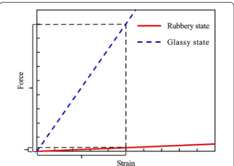
"Background” section, E can be changed according to the temperature. Therefore, the relationship between ε and W [namely Eq. (3)] can also be changed (Fig. 1). In Fig. 1, depending on the type of strain gauge and beam, the measurable strain range is determined (the range shown on the horizontal axis of Fig. 1). Since the stiffness of the SMP can be changed according to the temperature, the measurable force range (the range shown on the vertical axis of Fig. 1) determined by the above strain range can also be changed. Moreover, even if the strain resolution is the same, the force resolution can be changed similarly. In this way, the measurement range and sensitivity of the force sensor can be changed according to the tempera-ture. Note that this concept can be applied to other force sensors with different structures and measuring elements (it is not limited to strain gauges bonded to a bending beam).
Compared with the conventional force sensor, the new force sensor with SMP properties has the following advantages:
1. Since the measurement range and sensitivity can be changed, it is not necessary to replace the force sen-sor to match the measurement target.
2. Softening of the surface in the rubbery state could reduce the impact forces when the sensor moves and contacts an unexpected object.
First prototype Prototype
The prototype SMP force sensor (thickness: 1.2 mm) is shown in Fig. 2. Note that dimensions were not opti-mized, but can be scaled depending on the application.
In the present study, we chose a polyurethane SMP (SMP Technologies Inc., MP4510, Tg = 45 °C) and prepared
an SMP sheet with an embedded electrical heating wire in a manner similar to that described in our previous study [7]. The fundamental characteristics of this mate-rial taken from the product catalogue are summarized in Table 1. The coefficient of linear thermal expansion of the polyurethane SMP is 11.6 × 10⁻⁵ K−1 [10] and
larger than that of steel. The two liquid components were mixed, poured onto a plate, and cured. Then, the thick and non-uniform SMP sheet was pressed and heated (held at 190–200 °C for 10 min and cooled at ambient temperature for at least 30 min), and the SMP sheet re-memorized a thin uniform shape without air bubbles. In order to heat the SMP sheet, we placed a heating wire made of Nichrome (outer diameter: 0.26 mm, electrical resistivity: 108 × 10−6 Ω cm, Young’s modulus: 214 GPa
[20], coefficient of thermal expansion: 17.3 × 10⁻⁶ K−1
[20]) between two pressed SMP sheets, and the sheets were cohered to each other using a heat press (150 °C, 20 min). The heating wire is shaped like a square wave so as not to affect the mechanical properties of the SMP sheet. The total electrical resistivity is 5.7 Ω.
In order to measure the surface strain of the SMP sheet, we used two strain gauges (KFG-5-120-C1-16L3M2R, Kyowa Electronic Instruments Co. Ltd.) and attached one on each side of the SMP sheet with an embedded electri-cal heating wire using a cyanoacrylate adhesive (CC-36,
Kyowa Electronic Instruments Co. Ltd., operating tem-perature range: −30 to 100 °C). With the half-bridge sys-tem, the strain gauges were connected to the bridge, one each to adjacent sides, with a fixed resistor inserted on the other sides. The half-bridge system was used to elimi-nate strain components other than the target strain to compensate for the thermal expansion of the SMP sheet [21].
Experiments
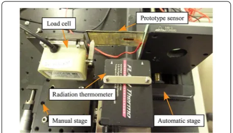
The experimental apparatus used to evaluate the pro-posed sensor is shown in Fig. 3. The applied force was measured when the SMP sheet was deformed in the bending direction. The SMP sheet was bent at tempera-tures above and below Tg. We evaluated the relationship
between the bending force and the strain when a bending force was applied to the sensor by an indenter connected to a load cell (LVS-500GA (T < Tg), LVS-50GA (T > Tg),
Kyowa Electronic Instruments Co. Ltd.). The load cell and the prototype sensor were attached on a manual and auto-matic stage (SGSP26-50, Sigma Koki Co., Ltd.), respec-tively. The prototype sensor was automatically displaced using the automatic stage at a constant speed (20 mm/s). The distance between the fixed part and the indenter was 50 mm. The applied alternating voltage on the heating wire was changed by a voltage controller. The experiments below Tg were performed at room temperature. The
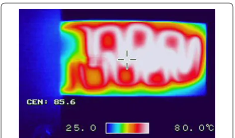
sur-face temperature was measured using a digital infrared temperature sensor (FT-H10, Keyence Co.). Since it was difficult to guarantee a uniform temperature of the SMP sensor, we raised the temperature to approximately 80 °C (significantly above the Tg of 45 °C) to ensure that all of
the SMP material in the sensor was well within the rub-bery state. The thermogram of the heated SMP sheet cap-tured by an infrared thermal camera (NEC Avio Infrared Technologies Co., Ltd, F30W) is shown in Fig. 4.
Fig. 2 First prototype force sensor using an SMP sheet with embed-ded electrical heating wire. In order to measure the surface strain of the SMP sheet, two strain gauges were bonded on each side of the SMP sheet
Table 1 Characteristics of SMP MP4510
a Bending modulus
b 100% tensile in the machine direction
Properties MP4510
Elastic modulus (T < Tg) (MPa) 1350a
Elastic modulus (T > Tg) (MPa) 4.5b
Elongation (T < Tg) (%) 300
From the relationship between the applied force and the strain obtained using the above experiment, we cal-culated the gradient of the linear approximation formula. We then compared the calculated force using the linear approximation formula with the applied force measured by the load cell. We measured these forces when the sen-sor tip was displaced randomly.
Results and discussions
The relationship between the applied force and the meas-ured strain below and above Tg is shown in Fig. 5. In this
figure, the relationship between the applied force and the strain calculated using Eq. (3) is also shown as “theo-retical” values. As shown in this figure, similarly to Fig. 2, the change in load for the same strain change can sig-nificantly vary according to the temperature. Namely, the sensor can measure a minute force above Tg. For
exam-ple, as can be seen from the gradient of the linear approx-imation formula, 100 με of strain change corresponds to 0.03 N (T < Tg) or 0.01 N (T > Tg) of applied force. For
conventional force sensors, it is necessary to replace the sensor for different measurement ranges and sensitivi-ties. However, by changing the temperature, our sensor can measure a large range of forces without replacing the sensor. As shown in this figure, the difference between the measured and theoretical values is large above Tg.
One reason is that the embedded heating wire is stiffer than the SMP sheet in the rubbery state, and the change of the elastic modulus between two states became small similarly to as observed in our previous study [7].
Substituting the strain measured by the prototype sensor into the linear approximation formula in Fig. 5, we calcu-lated the applied force and compared it with that obtained by the load cell when a random force was applied. Com-parisons of the two forces below and above Tg are shown
in Figs. 6 and 7, respectively. As shown in these figures, the two forces are almost identical in both experiments.
Namely, our sensor can accurately measure the applied force. In Figs. 6 and 7, the absolute average differences between the two forces are 0.0081 and 0.021 N, respec-tively. The differences correspond to 1.7 and 21% of each maximum measured force, respectively. As shown in Fig. 7, the difference between the two forces gradually increased above Tg. One reason is the creep deformation
of the SMP sheet. Another reason is that the SMP sheet could not recover to the initial shape quickly because of the viscosity of the SMP sheet, and the load could not accurately measure the force. Creep and stress relaxation are large in the SMP. Therefore, we will consider the effects of the viscous term and modify Eq. (3) in future studies. Fig. 4 Thermographic image of the prototype force sensor using an
SMP sheet heated above Tg
Fig. 5 Relationship between applied force and strain on SMP sheet (first prototype). The alternate long and short dash lines show linear approximation. The linear approximation formulae are also shown
Fig. 6 Comparison of two forces measured by first prototype sensor and load cell when a random force was applied (T < Tg). Substituting
Second prototype
Problems with prototype sensor
As shown in “First prototype” section, the strain measured by the prototype sensor is smaller than the theoretical values above Tg. One reason other than the stiffness of the
embed-ded heating wire described in “First prototype” section is that the difference in stiffness between the strain gauge and the SMP in the rubbery state is too large to transmit the deformation from the SMP to the strain gauge. Moreover, the adhesive would affect the mechanical properties of the attached surface of the SMP sheet. On the other hand, the changes in measurement range and sensitivity depend on the Young’s modulus of the SMP (a change of 100- to 1000-fold) and are not adjustable. However, the change may be too large for some application areas. Therefore, in this sec-tion, we improved the proposed sensor by bonding the SMP and steel sheet and attaching the strain gauge onto the steel.
Theory
We assumed that the embedded wire is negligible. When the composite beam using SMP and steel sheets (Fig. 8) is bent, R is expressed as follows [19]:
where EM and ET are the elastic moduli of SMP and steel,
respectively, and IM′ and IT′ are the area moments of iner-tia of the SMP and steel about the neutral axis of the composite beam, respectively. IM′ and IT′ are expressed as follows:
(4)
1 R =
Wx EMI
′ M+ETI
′ T
(5)
IM′ = bh
3 M
12 +
hN−hM
2 2
bhM
where hM and hT are the thicknesses of the SMP and steel
plates, respectively. hN is the distance between the
neu-tral axis and the SMP surface and expressed as follows:
From Eqs. (1) and (4), using the strain on the surface of the steel plate (ε), W is expressed as follows:
ε below and above Tg is expressed as εg and εr,
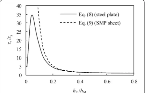
respec-tively. We calculated the relationship between hT/hM and
εr/εg substituting the dimension of the prototype (see
the next subsection for more details) and material prop-erties (Table 1) into Eq. (8) (Fig. 9). We assumed that ET = 193 GPa. As shown in this figure, by changing the
thickness of the steel plate, the change in strain based on temperature can be modified. Therefore, the change in the measurement range based on temperature can be modified. On the other hand, when the strain gauge is (6)
IT′ = bh
3 T
12 +
hM−hN+ hT
2
2 bhT
(7)
hN =
EMh2M+ET(2hMhT+h2T) 2(EMhM+EThT)
(8) W = (EMI
′ M+ETI
′ T)ε
(hM+hT−hN)x Fig. 7 Comparison of two forces measured by first prototype sensor
and load cell when a random force was applied (T > Tg). Substituting
the strain measured by the prototype sensor into the linear approxi-mation formula in Fig. 5, we calculated the applied force
attached on the SMP side, using the strain on the surface of the SMP sheet ( ε′
), W is expressed as follows:
We also calculated the relationship between hT/hM
and ε′
r/ε
′
g (dotted curve in Fig. 9). Although the change in strain based on temperature can also be modified by changing the thickness of the steel plate, the large differ-ence in stiffness between the strain gauge and the SMP would affect the measurement accuracy. Therefore, in this study, we attached the strain gauge on the steel plate. In future studies, we will consider another kind of design method to improve the force sensor, in which two stain-less plates are bonded to the two sides of the SMP sheet and the half-bridge system with two strain gauges are used. Moreover, the evaluation of the effect of different thickness SMP sheet is beyond the scope of this paper.
Prototype and experiments
The prototype of the SMP force sensor with a steel plate is shown in Fig. 10. The SMP sheet with the embedded heating wire was prepared similarly to that described in “First prototype” section. The total electrical resistiv-ity is 5.3 Ω. We bonded the SMP sheet (thickness (hM):
1.2 mm) and steel plate (SUS304H, thickness (hT): 0.05,
0.1, 0.2, 0.3, 0.5 mm) using double-sided tape. As the strains on the two surfaces are different, we cannot use the half-bridge system with two strain gauges. Therefore, we attached one strain gauge (KFG-5-120-C1-16L3M2R, Kyowa Electronic Instruments Co. Ltd.) onto the steel plate and measured the strain on the surface of the steel plate. We evaluated this prototype similarly to that described in the previous section.
(9) W = − (EMI
′
M+ETI
′
T)ε
′
hNx
.
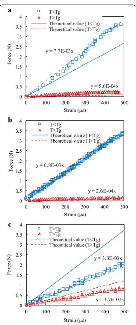
Results and discussions
Some results of the relationship between the measured strain and the applied force is shown in Fig. 11. In this fig-ure, “theoretical” values calculated using Eq. (8) and the linear approximation formula are also shown. As shown in this figure, the measured force range can be changed according to the thickness of the steel plate. On the other hand, the proposed sensor can measure a minute force above Tg, and the measured force range below Tg is larger
than that above Tg, similarly to Figs. 1 and 5. Moreover,
we could also construct a force sensor using both SMP and steel plates whose measurement can change accord-ing to the temperature without the replacaccord-ing the sensor. In Fig. 11a and b, the changes in gradients became larger than that shown in Fig. 5 because the difference in stiff-ness between the strain gauge and the steel plate is small, and the strain gauge became easy to deform. Further-more, the difference between the experimental and theo-retical values became small above Tg (Fig. 11).
The relationship between hT and εr/εg is shown in
Fig. 12. In this figure, the theoretical values calculated by Eq. (8) are also shown. The measured values are almost the same as those calculated using Eq. (8). However, when hT is small, the difference is large. One reason is the
effect of the embedded wire being relatively large when the steel plate is thin. Moreover, note that in practical applications it is more necessary for this type of sensor to maintain a constant temperature and eliminate the thermal expansion of the SMP than that shown in the previous section because there is only one strain gauge. Furthermore, we should consider the difference of the Fig. 9 Relationship between thickness (hT/hM) and strain ratios (εr/εg)
of second prototype sensor [theoretical value predicted by Eq. (8)]. Theoretical value predicted by Eq. (9) is also shown by dotted curve
thermal expansions between the SMP and the embedded Nichrome wire in future studies.
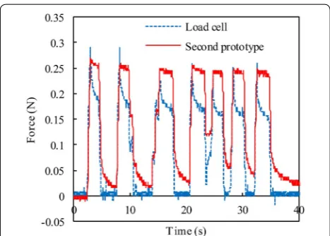
We compared the calculated force using the lin-ear approximation formula in Fig. 11 with the applied force measured by the load cell. As an example, when hT = 0.05 mm, the transitions of the force below and
above Tg are shown in Figs. 13 and 14, respectively. The
sensor tip was displaced randomly using a stage. As shown in Figs. 13 and 14, similarly to Figs. 6 and 7, the two measured forces are almost identical. In Figs. 13 and
14, the absolute average differences between the two forces are 0.19 and 0.042 N, respectively. The differences
Fig. 11 Relationship between applied force and strain on steel plate (second prototype): a hT = 0.05 mm, b hT = 0.1 mm, c hT = 0.3 mm.
The alternate long and short dash lines show linear approximation. The linear approximation formulae are also shown
Fig. 12 Relationship between hT and εr/εg of second prototype sen-sor. The theoretical values calculated by Eq. (8) are also shown
Fig. 13 Comparison of two forces measured by second prototype sensor and load cell when a random force was applied (T < Tg,
correspond to 5.2 and 14% of each maximum measured force, respectively. Moreover, although we applied a simi-lar displacement below and above Tg, the measured force
range is significantly different.
Conclusion
We have developed a force sensor using an SMP sheet with an embedded electrical heating wire. In this study, we evaluated two types of prototype sensors. Through experiments on the prototypes, which utilize the stiffness change of the SMP based on the temperature, we showed that with the proposed sensor the measurement range and sensitivity can be changed without replacing the actual sensor. The first prototype consists of strain gauges bonded to the bending SMP beam. Moreover, by adding a steel plate, we fabricated a second prototype. The sec-ond proposed sensor can be improved and can alter the change ratio of the strain according to the thickness of the steel plate.
Authors’ contributions
KT conceived and led the study, and wrote this paper as corresponding author. HK developed the sensor, carried out all experiments, and analyzed data. MT and TM participated in the research design. All authors read and approved the final manuscript.
Author details
1 Graduate School of Life Science and Systems Engineering, Kyushu Institute of Technology, 2-4 Hibikino, Wakamatsu-ku, Kitakyushu 808-0196, Japan. 2 Kagawa Prefectural Industrial Technology Research Center, 587-1 Goto-cho, Takamatsu 716-8031, Japan. 3 Department of Information Engineering, Faculty of Science and Technology, Meijo University, 1-501 Shiogamaguchi, Tenpaku-ku, Nagoya 468-8502, Japan.
Acknowledgements
Not applicable.
Competing interests
The authors declare that they have no competing interests.
Publisher’s Note
Springer Nature remains neutral with regard to jurisdictional claims in pub-lished maps and institutional affiliations.
Received: 8 March 2017 Accepted: 6 June 2017
References
1. Mukai T, Hirano S, Yoshida M, Nakashima H, Guo S, Hayakawa Y (2011) Manipulation using tactile information for a nursing-care assistant robot in whole-body contact with the object. Trans JSME 77-C:3794–3807 2. Asakura A, Fukuda T, Arai F, (2008) Design, fabrication and
characteriza-tion of compact force sensor using AT-cut quartz crystal resonators In: IEEE/RSJ international conference on intelligent robots and systems (IROS). IEEE, Nice, France, pp 506–511
3. Liu Y, Gall K, Dunn ML, Greenberg AR, Diani J (2006) Thermomechan-ics of shape memory polymers: uniaxial experiments and constitutive modeling. Int J Plast 22:279–313
4. Takashima K, Zhang N, Mukai T, Guo S (2010) Fundamental study of a position-keeping module using a shape-memory polymer. J Robot Soc Jpn 28:905–912
5. Takashima K, Rossiter J, Mukai T (2010) McKibben artificial muscle using shape-memory polymer. Sensors Actuators A 164:116–124
6. Takashima K, Noritsugu T, Rossiter J, Guo S, Mukai T (2012) Curved type pneumatic artificial rubber muscle using shape-memory polymer. J Robotics Mechatron 24:472–479
7. Takashima K, Sugitani K, Morimoto N, Sakaguchi S, Noritsugu T, Mukai T (2014) Pneumatic artificial rubber muscle using shape-memory polymer sheet with embedded electrical heating wire. Smart Mater Struct 23:125005
8. Rossiter J, Takashima K, Mukai T (2012) Shape memory properties of ionic polymer–metal composites. Smart Mater Struct 21:1–7
9. Rossiter J, Takashima K, Scarpa F, Walters P, Mukai T (2014) Shape memory polymer hexachiral auxetic structures with tunable stiffness. Smart Mater Struct 23:045007
10. Tobushi H, Hayashi S, Yamada E, Hashimoto T (1998) Constitutive mod-eling for thermomechanical properties in shape memory polymer of polyurethane series. Trans JSME 64-A:186–192
11. Behl M, Lendlein A (2007) Shape-memory polymers. Mater Today 10:20–28
12. Leng J, Lan X, Liu Y, Du S (2011) Shape memory polymers and their com-posites: stimulus methods and applications. Prog Mater Sci 56:1077–1135 13. Meng H, Mohamadian H, Stubblefield M, Jerro D, Ibekwe S, Pang S, Li
G (2013) Various shape memory effects of stimuli-responsive shape memory polymers. Smart Mater Struct 22:093001
14. Liu Y, Du H, Liu L, Leng J (2014) Shape memory polymers and their com-posites in aerospace applications: a review. Smart Mater Struct 23:023001 15. Xie F, Huang L, Leng J, Liu Y (2016) Thermoset shape memory polymers
and their composites. J Intell Mater Syst Struct 27:2433–2455
16. Xiao X, Qiu X, Kong D, Zhang W, Liu Y, Leng J (2016) Optically transparent high temperature shape memory polymers. Soft Matter 12:2894–2900 17. Yang Y, Chen Y, Li Y, Chen MZ, 2016 3D printing of variable stiffness
hyper-redundant robotic arm. In: Proceedings of the 2016 IEEE international conference on robotics & automation (ICRA). IEEE, Stockholm, Sweden, pp 3871–3877
18. Jani JM, Leary M, Subic A, Gibson MA (2014) A review of shape memory alloy research, applications and opportunities. Mater Des (1980–2015) 56:1078–1113
19. Shibata T, Otani R, Komai K, Inoue T (1991) Zairyo Rikigaku No Kiso. Baifu-kan, Tokyo
20. The Japan Society of Mechanical Engineers (ed) (2014) JSME Mechani-cal Engineers’ Handbook DVD-ROM. The Japan Society of MechaniMechani-cal Engineers, Tokyo
21. Kyowa Electronic Instruments Co., Ltd (2005) What’s a strain gage (Intro-duction to strain gages). https://www.kyowa-ei.co.jp/english/products/ gages/pdf/whats.pdf. Accessed 8 Mar 2017
Fig. 14 Comparison of two forces measured by second prototype sensor and load cell when a random force was applied (T > Tg,