RESEARCH
Multi-slice frozen phonon simulations
of high-angle annular dark field scanning
transmission electron microscopy images
of the structurally and compositionally complex
Mo–V–Nb–Te oxide catalyst
Douglas A. Blom
1*and Thomas Vogt
2Abstract
We report frozen phonon multi-slice image simulations for the complex oxidation catalyst M1. Quantitative analysis of the simulations suggests that the detailed order of the cations along the electron propagation direction in a [001] zone axis orientation can lead to different high-angle annular dark field signals from atomic columns with identical composition. The annular dark field signal varies linearly with atomic percent V, and the spread of intensities due to the atomic species order is of similar magnitude to the intensity difference due to ± 5% V.
Keywords: Frozen phonon multi-slice, M1 catalyst, Quantitative HAADF-STEM
© The Author(s) 2018. This article is distributed under the terms of the Creative Commons Attribution 4.0 International License (http://creat iveco mmons .org/licen ses/by/4.0/), which permits unrestricted use, distribution, and reproduction in any medium, provided you give appropriate credit to the original author(s) and the source, provide a link to the Creative Commons license, and indicate if changes were made.
Background
Annual worldwide acrylonitrile (ACN) production is nearly 1 kg/person [1]. Currently, production uses the “SOHIO process” originally developed in the 1950s [2]. Propylene is reacted over a multi-phase catalyst in the presence of ammonia. For both economic and energy use reasons, there is a strong desire to produce acryloni-trile using propane as starting material. This requires the development of a new catalyst. The most promising cata-lyst for the direct ammoxidation of propane to acryloni-trile is a quaternary Mo–V–Nb–Te oxide phase originally reported by the Mitsubishi Chemical Co., and therefore, typically referred to in the literature as “M1”. The crys-tal structure was originally solved with the combined Rietveld refinement of synchrotron X-ray and neutron powder diffraction data [3]. More recently, the model was improved [4] due to input from high angle annu-lar dark field (HAADF) scanning transmission electron
microscope (STEM) observations [5]. Figure 1 reveals the structural model of the cation positions in this phase in a [001] orientation. The colors in the figure correspond to the crystallographically distinct cation columns. The unit cell consists of a series of pentagonal, hexagonal and heptagonal rings of metal–oxygen octahedral and is one octahedron thick along the c-axis. The pentagonal ring is dark red, the hexagonal ring is green and the heptagonal ring is light blue in Fig. 1. The center of the pentagonal ring is occupied by Nb. Te and oxygen chains are pre-sent in both the hexagonal and heptagonal channels. The other ten crystallographically distinct cation sites are populated by various mixtures of Mo and V as shown in Fig. 1.
HAADF STEM has become a common characteriza-tion technique for M1 and a number of isostructural phases with various elemental compositions [6–10]. The initial work in [5] was followed by analysis of M1 phases with different synthesis conditions [6]. The pri-mary difference was found to be in the Te–O chains. The framework of the phases was unaffected by the change in the synthesis type. By replacing the Nb with Ta, HAADF STEM was able to demonstrate that the Ta
Open Access
*Correspondence: [email protected]
1 NanoCenter and Department of Chemical Engineering, University of South Carolina, Columbia, SC 29201, USA
was incorporated into the center of the pentagonal unit both for an ambient pressure “slurry” synthesis [7] and a hydrothermal synthesis [9] suggesting that the Nb in the traditional M1 phase will also be incorporated into
the center of the pentagonal unit as originally suggested by the Rietveld refinement model of [3].
12], intergrowths of several of these phases [13, 14] as well as the initial formation of nascent crystallites [15]. The effects of heating [16] and in situ heating, and gas exposure on the structure and composition of M1 phases [17, 18] have been studied using HAADF-STEM. In all of these reports, the analysis of the STEM data was focused on either the spatial location of the atomic columns in the [001] orientation or a qualitative analysis of the inten-sity of the HAADF-STEM images using an incoherent imaging model.
The propane ammoxidation activity and selectivity of the M1 catalyst and a number of chemically and struc-turally related oxide phases varies widely in the literature depending on a number of factors which are not fully understood [19]. One of the proposed catalytic mecha-nisms suggests that the local distribution of V5+ ions on
the surface is an important parameter to achieve simul-taneously a high conversion rate for propane and high selectivity to the desired ACN product [20]. Recently, He et al. [14] reported on the design of a mesoscale intergrown catalyst of M1 and M2, providing clear evi-dence that this proposed mechanism is correct. There-fore, the spatial distribution of V in these catalysts may be key to understanding and hopefully optimizing their performance.
The potential ability of Z-contrast STEM to provide localized information regarding the mass thickness of a specimen is uniquely suited to characterizing the V dis-tribution in these materials. Multi-slice image simula-tions will be required to make quantitative comparisons between HAADF STEM images and atomic column compositions. Recently, Epicier et al. [21] reported on the spatial distribution of V using a combination of HAADF STEM and multi-slice image simulations. They found that their images followed a power-law relation-ship between mass thickness and image intensity. For the closely related MoVTeTaO system, Woo et al. [22,
23] performed quantitative analysis of HAADF-STEM images to deduce the V distribution. The two reports do not agree regarding the relationship between the STEM image contrast and atomic column composition. Both groups reported V concentrations derived from measure-ments of HAADF STEM images to a precision of 1% V or better. Neither report addressed the role the order of the Mo and V atoms in an atomic column will have on the STEM image intensity. Heidelmann et al. [10] have recently published data on a closely related compound, Cs0.44[Nb2.54W2.46O14], demonstrating a linear relation-ship between W content and ADF STEM intensity for a variety of thicknesses. They reported that the ordering of the Nb and W atoms in the column produced as much as a 10% change in simulated ADF image intensities.
Previously, we have published results of multi-slice ADF STEM image simulations on this material [24, 25]. The virtual crystal approximation (VCA) was used in the published simulations. This means that the pro-jected potential of the cation sites with partial substitu-tion of Mo and V in the VCA is the weighted average of the potentials of Mo and V regardless of their order. For STEM, the ADF signal is sensitive to not only the aver-age mass of the cations but also the location of the cati-ons along the beam propagation direction primarily due to the effect of electron channeling [26]. In this work, we report the results of multi-slice ADF STEM image simu-lations based on the improved structural model [4] with-out using the VCA.
Methods
A number of simulations were performed in which the order of the cations along the beam direction was var-ied while maintaining an overall stoichiometry consist-ent with the refined crystallographic model for each cation site. A random solid solution was assumed in building these models. As a compromise between CPU time requirements and ability to simulate closely related V compositions, a sample thickness of 30 cations along <001> was chosen. A random number generator was run 30 times for each cation site to generate a list of V and Mo cations consistent with the model structure occu-pancy or in the case of the Te-intercalated sites, a list of occupied and unoccupied Te–O chains. The input struc-ture file for the multi-slice image simulations was a list of 4757 atom positions and thermal parameters.
than 1/4 of the unit cell which contained all the cation sites of the structure (see Fig. 1) for a total of 163 lines of 135 pixels each. The simulated thickness was 30 unit cells along the c-axis (12 nm), which allows for 30 dif-ferent cations along the electron propagation direction. The atomic coordinates, isotropic thermal parameters, and occupancy were taken from [4]. Because of the finite number of cations, the composition at each site was quantized in 3.3% substitutional increments. Table 1 lists the refined V concentrations for the various cation sites, the V content used in the image simulations and the pos-sible number of different atomic configurations for each cation site consistent with the composition. For example, cation site S1 has a composition of 30% V, or 9 V atoms and 21 Mo atoms. There are 30!/9!21! different ways to arrange this collection of atoms. Each simulated con-figuration required 1.1 CPU years to complete, preclud-ing the calculation of more cation distributions. Figure 2
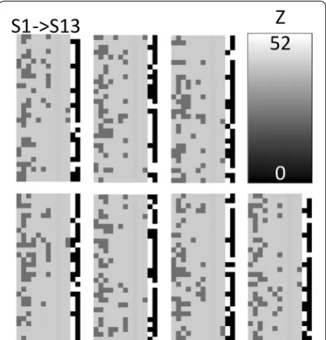
is a graphical representation of the cation distributions along the beam direction for the 13 independent cation sites from S1 to S13 from left to right. S9 contains the Nb in this model and S12 and S13 are the intercalated Te–O sites. The intensity is equal to the atomic number of the cation for all 30 possible locations. The last two columns are the Te-containing sites that are either vacant or con-tain Te–O chains.
Results and discussion
Figure 3 shows the simulation results of one of the atomic configurations. The image displayed is in units of per-centage of the initial probe current and varies between 0.1 and 15.1%. In the simulation, there are multiple ver-sions of sites S1, S2 and S10. Only one was used for the data analysis. Even though Nb is slightly lighter than Mo, Table 1 Possible combinations for Mo/V mixed cation sites, V content from the model structure, and input for the multi-slice simulations
Cation site Combinations V concentration (%) Model
structure [4] Image simulation
S1 14307150 30.1 30
S2 119759850 57.9 56.6¯
S3 86493225 42.7 40
S4 593775 19.6 20
S5 30 4.6 3.3¯
S6 4060 11.7 10
S7 2035800 24.0 23.3¯
S8, S10 1 0 0
S11 435 5.2 6.6¯
Fig. 2 Graphical representation of the seven distinct configurations simulated in this study. Atomic sites S1–S13 from left to right. Each column corresponds to a particular cation site in the structure, while the intensity is equal to the atomic number of the cation. The last two columns on the right correspond to the Te–O chains in the hexagonal and heptagonal sites, respectively. The stoichiometry of each cation site is identical for all the configurations, while the location of the V substitution varies for each. A random solid solution was assumed in building these model configurations
the Nb column appears much brighter than either of the two fully Mo-occupied sites, due to the much smaller thermal parameter for the Nb site in the model struc-ture. The Te–O chains inside the heptagonal channels scattered 1.5% of the initial probe current according to the simulations and are not visually apparent. The Te–O chains in the hexagonal channels are 70% filled in the simulation, scattered almost 11% of the initial probe cur-rent and are clearly visible.
The regions of interest (ROIs) used to extract quantita-tive ADF image intensity values for the M1 cation sites are shown as red boxes in Fig. 4. Figure 4 corresponds to a 3a × 3b projected area produced by appropriately tiling the image simulation results using the symmetry of the unit cell. Intensity scale is identical to Fig. 3. Quantifica-tion of the HAADF image intensity was performed by integrating the HAADF signal inside each ROI.
Figure 5 shows the variation of the HAADF intensity due to the distribution of Mo and V along [001] for cat-ion site S3 (40% V). For the configuratcat-ions considered, the Student’s t distribution 95% confidence limits of the mean intensity become relatively narrow after only Fig. 4 3a × 3b tiled image simulation results. The regions of interest
used in the image quantification are shown as red boxes. Intensity scale is in percent of initial probe
four different configurations. The additional configura-tions make only a small difference, suggesting that the detailed order of Mo and V along the beam direction plays a relatively minor role in the integrated HAADF intensity for the configurations considered here. The other cation sites exhibited a similar behavior, lead-ing us to confine ourselves to seven different atomic configurations.
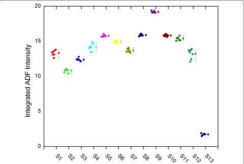
Figure 6 is a box plot for all 13 cations sites in M1. The individual data points are shown to the left of the mean and 95% Student’s t distribution confidence lim-its. Sites 8 and 10 are fully Mo occupied and site 9 is 100% Nb. The narrow confidence limits for these sites indicates that the sampling of the simulations (real and reciprocal space) and number of phonon passes is suffi-cient for high accuracy in the simulations. Sites S12 and S13 are the intercalated Te–O sites.
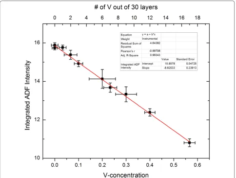
Figure 7 plots the mean-integrated HAADF intensity as a function of the V content. Symbols mark the mean. The Y error bars are the 95% confidence limits. The red line is a linear regression to the means. The mean ADF intensity in M1 is well described by a linear change in
intensity with V content for the conditions considered here. The X error bars are the apparent uncertainty in V content from the intensity confidence limits and the slope of the regression. In general, the variability due to order along the beam propagation direction is ≈± 1 atom of V out of the 30 unit cells in these simulations. In other words, the detailed ordering of the Mo and V along the columns for an identical composition leads to changes in ADF image intensity equivalent to an uncer-tainty in the composition of ± 3.3 atomic % V. In the worst cases, the uncertainty in the V concentration is equivalent to ± 2 atoms (i.e., ± 6.6% V). Given these results, it seems unlikely that quantitative HAADF STEM of M1 will be able to determine the V content in an atomic column to the precision previously reported [21–23].
These image simulations have not considered many of the artifacts observed in experimental quantitative HAADF STEM. Incoherent blurring of experimental HAADF STEM images is a well-known phenomenon. By integrating the output of the multi-slice HAADF STEM image simulations, these incoherent effects will
be less important. Electron dose sensitivity will add an additional uncertainty in the quantification of experi-mental HAADF images, as will amorphous surface layers and carbon contamination. While other experi-mental difficulties need to be considered, these image simulation results suggest that for Mo/V-substituted atomic columns, the order of the cations along the beam propagation direction do contribute to measure-able differences in integrated HAADF signals from col-umns of identical composition, limiting the precision of assigning a composition to any particular atomic column.
Conclusions
Our frozen phonon multi-slice HAADF image simula-tions have shown that for atomic columns with alternat-ing O and either Mo or V, as found in MoV bronzes, the sequence along the electron beam direction has a rela-tively minor effect on the ADF intensity at the atomic
column location. The mean ADF intensity varies linearly with V content up to 56% V. However, the uncertainty of the V concentration does not vary linearly but peaks for compositions near 25% V for the limited number of atomic configurations considered. Based on these simula-tions, quantitative ADF STEM may at best be able to dis-tinguish atomic columns which have a V content that is 5% different for the limited set of conditions considered here. Other instrumental parameters or sample thick-ness may have different quantitative results. Regardless, the VCA is not appropriate to apply to multi-slice image simulations of the M1 phase. Image simulations which consider different ordering of cations in the sample matching experimental conditions should be considered before making quantitative statements assigning V con-tent based solely on HAADF STEM image data.
Abbreviations
ACN: acrylonitrile; HAADF: high-angle annular dark field; ROI: region of interest; STEM: scanning transmission electron microscopy; VCA: virtual crystal approxi-mation; XSEDE: extreme science and discovery environment.
Authors’ contributions
DB performed the image simulations, extracted the data, prepared the figures and contributed to writing the manuscript. TV was a major contributor to writ-ing the manuscript. Both authors read and approved the final manuscript.
Author details
1 NanoCenter and Department of Chemical Engineering, University of South Carolina, Columbia, SC 29201, USA. 2 NanoCenter and Department of Chemis-try & BiochemisChemis-try, University of South Carolina, Columbia, SC 29201, USA.
Acknowledgements Not applicable.
Competing interests
The authors declare that they have no competing interests.
Availability of data and materials
The datasets used and/or analyzed during the current study are available from the corresponding author on reasonable request.
Funding
National Academies Keck Future Initiative. This work used the Extreme Science and Engineering Discovery Environment (XSEDE), which is supported by National Science Foundation grant number ACI-1053575. Vice President of Research, University of South Carolina.
Publisher’s Note
Springer Nature remains neutral with regard to jurisdictional claims in pub-lished maps and institutional affiliations.
Received: 21 June 2018 Accepted: 24 July 2018
References
1. World acrylonitrile production to reach 7 Mln tonnes in 2017, according to merchant research & consulting report. Available at MarketPublishers. com. http://www.prweb .com/relea ses/2014/04/prweb 11740 156.htm. Accessed 19 Feb 2015
2. American Chemical Society National Historic Chemical Landmarks. Sohio acrylonitrile process. http://www.acs.org/conte nt/acs/en/educa tion/ whati schem istry /landm arks/acryl onitr ile.html. Accessed 19 Feb 2015 3. DeSanto Jr., P., Buttrey, D.J., Grasselli, R.K., Lugmair, C.G., Volpe Jr., A.F., Toby,
B.H., Vogt, T.: Structural aspects of the M1 and M2 phases in MoVNbTeO propane oxidation catalysts. Z. Kristallogr. 219, 152–165 (2004) 4. Li, X., Buttrey, D.J., Blom, D.A., Vogt, T.: Improvement of the structural
model for the M1 phase Mo–V–Nb–Te–O propane (Amm)oxidation catalyst. Top. Catal. 54, 614–626 (2011)
5. Pyrz, W.D., Blom, D.A., Vogt, T., Buttrey, D.J.: Direct imaging of the MoVNeTeO M1 phase using an aberration-corrected high-resolution scanning transmission electron microscope. Angew. Chem. Int. Ed. 47, 2788–2791 (2008)
6. Pyrz, W.D., Blom, D.A., Shiju, N.R., Guliants, V.V., Vogt, T., Buttrey, D.J.: Using aberration-corrected STEM imaging to explore chemical and structural variations in the M1 phase of the MoVNbTeO oxidation catalyst. J. Phys. Chem. C 112, 10043–10049 (2008)
7. Pyrz, W.D., Bom, D.A., Shiju, N.R., Guliants, V.V., Vogt, T., Buttrey, D.J.: The effect of Nb or Ta substitution into the M1 phase of the MoV(Nb, Ta) TeO selective oxidation catalyst. Cat. Today 142, 320–328 (2009) 8. Sadakane, M., Yamagata, K., Kodato, K., Endo, K., Toriumi, K., Ozawa,
Y., Ozeki, T., Nagai, T., Matsui, Y., Sakaguchi, N., Pyrz, W.D., Buttrey, D.J., Blom, D.A., Vogt, T., Ueda, W.: Synthesis of orthorhombic Mo–V–Sb-oxide species by assembly of pentagonal Mo6O21 polyoxometalate building blocks. Angw. Chem. Int. Ed. 48, 3782–3786 (2009)
9. Yu, J., Woo, J., Borisevich, A., Xu, Y., Guliants, V.V.: A combined HAADF STEM and density functional theory study of tantalum and niobium locations in the Mo–V–Te–Ta (Nb) O M1 Phases. Catal. Commun. 29, 68–72 (2012)
10. Heidelmann, M., Barthel, J., Cox, G., Weirich, T.E.: Periodic cation segrega-tion in Cs0.44[Nb2.54W2.46O14] quantified by high-resolution scanning transmission electron microscopy. Microsc. Microanal. 20, 1453–1462 (2014)
11. Blom, D.A., Pyrz, W.D., Vogt, T., Buttrey, D.J.: Aberration-corrected STEM investigation of the M2 phase of MoVNbTeO selective oxidation catalyst. J. Electr. Microsc. 58, 193–198 (2009)
12. Pyrz, W.D., Blom, D.A., Sadakane, M., Kodato, K., Ueda, W., Vogt, T., Buttrey, D.J.: Atomic-scale investigation of two-component MoVO complex oxide catalysts using aberration-corrected high-angle annular dark-field imag-ing. Chem. Mater. 22, 2033–2040 (2010)
13. Pyrz, W.D., Blom, D.A., Sadakane, M., Kodato, K., Ueda, W., Vogt, T., Buttrey, D.J.: Atomic-level imaging of Mo–V–O complex oxide intergrowth grain boundaries, and defects using HAADF-STEM. PNAS 107, 6152–6157 (2010)
14. He, Q., Woo, J., Belianinov, A., Guliants, V.V., Borisevich, A.Y.: Better catalysts through microscopy: mesoscale M1/M2 intergrowth in molybdenum-vanadium based complex oxide catalysts for propane ammoxidation. ACS Nano 9, 3470–3478 (2015)
15. Vogt, T., Blom, D.A., Jones, L., Buttrey, D.J.: ADF-STEM imaging of nascent phases and extended disorder within the Mo–V–Nb–Te–O catalyst system. Top. Catal. 59, 1489–1495 (2016)
16. Blom, D.A., Vogt, T., Allard, L.F., Buttrey, D.J.: Observation of sublattice disor-dering of the catalytic sites in a complex Mo–V–Nb–Te–O oxidation catalyst using high temperature STEM imaging. Top. Catal. 57, 1138–1144 (2014) 17. Aouine, M., Epicier, T., Millet, J.M.M.: In situ environmental STEM study of the
MoVTe oxide M1 phase catalysts for ethane oxidative dehydrogenation. ACS Catal. 6, 4775–4781 (2016)
18. Zhu, Y., Sushko, P.V., Melzer, D., Jensen, E., Kovarik, L., Ophus, C., Sanchez-Sanchez, M., Lercher, J.A., Browning, N.D.: Formation of oxygen radical sites on MoVNbTeOx by cooperative electron redistribution. JACS 139, 12342–12345 (2017)
19. Grasselli, R.K., Burrington, J.D., Buttrey, D.J., De Santo Jr., P., Lugmair, C.G., Volpe Jr., A.F., Weingand, T.: Multifunctionality of active centers in (amm) oxidation catalysts: from Bi–Mo–Ox to Mo–V–Nb–(Te, Sb)–Ox. Top. Catal. 23, 5–22 (2003)
20. Grasselli, R.K., Lugmair, C.G., Volpe Jr., A.F.: Towards an understanding of the reaction pathways in propane ammoxidation based on the distribution of elements at the active centers of the M1 phase of the MoV(Nb, Ta)TeO system. Top. Catal. 54, 595–604 (2011)
21. Epicier, T., Aouine, M., Nguyen, T.T., Millet, J.M.M.: Spatial distribution of the vanadium atomic species in MoVTeO and MoVTeNbO oxide catalysts as revealed by STEM–HAADF. ChemCatChem 9, 3526–3533 (2017)
22. Woo, J., Borisevich, A., Koch, C., Guliants, V.V.: Quantitative analysis of HAADF-STEM images of MoVTeTaO M1 phase catalyst for propane ammoxidation to acrylonitrile. ChemCatChem 7, 3731–3737 (2015)
23. Woo, J., Guliants, V.V.: QSTEM-based HAADF-STEM image analysis of Mo/V distribution in MoVTeTaO M1 phase and their correlations with surface reactivity. Appl. Catal. A 512, 27–35 (2016)
24. Blom, D.A.: Multislice frozen phonon high angle annular dark-field image simulation study of Mo–V–Nb–Te–O complex oxidation catalyst “M1”. Ultra-microscopy 112, 69–75 (2012)
25. Blom, D.A., Li, X., Mitra, S., Vogt, T., Buttrey, D.J.: STEM HAADF image simula-tion of the orthorhombic M1 phase in the Mo–V–Nb–Te–O propane oxida-tion catalyst. ChemCatChem 3, 1028–1033 (2011)
26. Carlino, E., Grillo, V.: Atomic-resolution quantitative composition analysis using scanning transmission electron microscopy Z-contrast experiments. Phys. Rev. B 71, 235303 (2005)
27. Kirkland, E.J.: Advanced computing in electron microscopy, 2nd edn. Springer, New York (2010)
![Fig. 1 Cation positions in the [001] projection of the MoVNbTe oxide M1 catalyst. Site colors correspond to crystallographically distinct cation sites](https://thumb-us.123doks.com/thumbv2/123dok_us/910129.1588785/2.595.60.538.85.593/cation-positions-projection-movnbte-catalyst-correspond-crystallographically-distinct.webp)
![Figure 5due to the distribution of Mo and V along [001] for cat- shows the variation of the HAADF intensity ion site S3 (40% V)](https://thumb-us.123doks.com/thumbv2/123dok_us/910129.1588785/5.595.58.290.86.319/figure-due-distribution-shows-variation-haadf-intensity-site.webp)