www.j-sens-sens-syst.net/3/9/2014/ doi:10.5194/jsss-3-9-2014
©Author(s) 2014. CC Attribution 3.0 License.
Open
Access
JSSS
Journal of Sensors and Sensor Systems
Gas identification based on bias induced hysteresis of a
gas-sensitive SiC field effect transistor
M. Bastuck1, C. Bur1,2, A. Lloyd Spetz2, M. Andersson2, and A. Schütze1
1Lab for Measurement Technology, Saarland University, Saarbrücken, Germany
2Div. of Applied Sensor Science, Linköping University, Linköping, Sweden
Correspondence to: M. Bastuck ([email protected])
Received: 26 November 2013 – Accepted: 4 January 2014 – Published: 17 January 2014
Abstract. In this work dynamic variation of gate bias is used on a gas-sensitive SiC field effect transistor (“GasFET”) to optimize its sensitivity and increase its selectivity. Gate bias ramps introduce strong hysteresis in the sensor signal. The shape of this hysteresis is shown to be an appropriate feature both for the discrimi-nation of various gases (ammonia, carbon monoxide, nitrogen monoxide and methane) as well as for different gas concentrations (250 and 500 ppm). The shape is very sensitive to ambient conditions as well as to the bias sweep rate. Thus, the influences of oxygen concentration, relative humidity, sensor temperature and cycle duration, i.e., sweep rate, are investigated and reasons for the observed signal changes, most importantly the existence of at least two different and competing processes taking place simultaneously, are discussed. Fur-thermore, it is shown that even for very fast cycles, in the range of seconds, the gas-induced shape change in the signal is strong enough to achieve a reliable separation of gases using gate bias cycled operation and linear discriminant analysis (LDA) making this approach suitable for practical application.
1 Introduction
Lundström et al. (2007) reported in 1975 for the first time that a field effect transistor with a palladium gate is sensitive to hydrogen. Hydrogen adsorbs and dissociates into ions on the palladium coated gate. The protons diffuse rapidly through the dense metal film and form a polarized layer at the metal– oxide interface. This changes the electric field in the oxide,
Schalwig et al. (2002) suggested a spillover of adsorbed oxygen ions as a possible explanation for the detection of nonpolar, (non-)hydrogen containing gases. The negatively charged oxygen ions on the gate oxide influence the electric field, hence the channel conductivity, and can be removed by reducing gases (e.g., CO; nitrogen monoxide, NO; or methane, CH4) similar to the sensing mechanism of resistive type metal oxide gas sensors. CO, NO and CH4are chosen as test gases since they are present in the exhaust stream of
a combustion engine. The amount of NOx can be reduced
by adding NH3(in the form of urea) before the catalytic con-verter in selective catalytic reduction (SCR) systems. Ideally, there should be no hazardous NH3left after the catalytic re-duction. Exact control of an SCR system thus requires se-lective detection and quantification of relevant exhaust gas components. Thus, the four mentioned gases were chosen for testing the potential of gate bias cycled operation (GBCO) for sensitive and selective detection in various background gases, e.g., pure nitrogen and air with and without humidity. Chemical gas sensors in general suffer from poor selec-tivity. Lee and Reedy (1999) have reviewed the potential of temperature cycled operation (TCO) to increase the selec-tivity of semiconductor gas sensors. Regarding sensiselec-tivity, which changes nonlinearly with the temperature, cyclic op-eration implicitly includes the point of highest sensitivity for each gas in a given mixture thus optimizing sensitivity. Bur et al. (2012b) extended this approach to GasFETs. In addition to temperature changes, FET-type sensors also allow chang-ing of the gate bias. For solid electrolyte amperometric NOx sensors, Schmidt-Zhang et al. (2000) have already shown that different biases can effectively be applied to influence sur-face reactions and thus the sensor selectivity. Nakagomi et al. (2005) have studied the influence of a constant gate bias on the sensing properties. They found a change in the thresh-old voltage as well as in sensitivity depending on the gate bias voltage. Thus, cyclic changing of the gate bias again op-timizes the sensitivity for all gases and furthermore leads to an enhancement of the selectivity (Bur et al., 2012a), similar to TCO.
Changing the gate bias dynamically, however, leads to strong hysteresis effects (Bastuck et al., 2013), an effect also observed for other transistor type sensors (Petit et al., 2008). Paska and Haick (2012) reported that the hystere-sis is strongly affected by trapping and release of charges mostly occurring in the underlying oxide layer of the FET. Usually, this is unwanted and much effort is spent on trying to reduce the hysteresis (Mattmann et al., 2009). However, Schütze et al. (2004) have shown for metal oxide semicon-ductor (MOS) sensors that the occurrence of hysteresis also means that there is additional information in the transient be-havior of the sensor, which can be used to increase selectiv-ity.
In this paper, we study the potential of extracting informa-tion from the hysteresis curves obtained by GBCO for im-proving the sensor performance in terms of selectivity, but
also to achieve a better understanding of the various pro-cesses occurring on the sensor surface. For demonstrating the potential of this novel method, fast gate bias cycling was also combined with temperature variation as proposed by Bur et al. (2013).
2 Experimental setup
2.1 Sensor device and sensor hardware
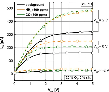
A depletion type SiC GasFET (SenSiC AB, Kista, Sweden) with porous platinum gate (Fig. 1a, b), as described by An-dersson et al. (2013), was used for all measurements pre-sented here. The sensor die is mounted on a ceramic heater (Heraeus GmbH, Hanau, Germany) and the temperature is controlled by a Pt100 temperature sensor (Heraeus GmbH, Hanau, Germany) located next to it. For sensor control and data acquisition a combined system developed by 3S GmbH, Saarbrücken, Germany, was used. The temperature is con-trolled by an analog circuit with an accuracy of 1◦C. The gate bias can be set from−7 V to+7 V using an 8 bit DAC, i.e., with a resolution of approximately 50 mV. Data acquisi-tion is performed with a 10 bit ADC for measuring the drain-source current with a measurement range of 0–1000µA, re-sulting in a resolution of approximately 1µA. The acquisi-tion rate for all measurements was 10 Hz. The recorded sen-sor signal is the drain-source current IDSat constant voltage VDS=2 V. Figure 2 shows typical IV curves of the tested de-vices showing the dependence of the sensitivity (here highest at VGS=2 V) and selectivity (here highest at VGS=0 V) on the gate bias at 200◦C in dry air. The constant drain-source voltage of VDS=2 V was chosen because this marks the on-set of the saturation region at VGS=0 V without gas and thus provides a large dynamic range, which is important for dy-namic operation of gas sensors.
2.2 Measurement setup
In order to study the influence of the gate bias the sensor was exposed to several, typical exhaust gases under various conditions. As test gases CO, NO and CH4as well as NH3 were chosen; each test gas was tested at a concentration of 500 ppm, and for NH3and CO additionally at 250 ppm. Mea-surements were carried out in pure nitrogen and in synthetic air, both in dry and humid (50 % relative humidity, RH) at-mospheres in order to study the influence of oxygen and wa-ter vapor. The sensor was mounted in a stainless steel test chamber with a volume of 3 mL and the total flow over the sensor was kept constant at 100 mL min−1.
The sensor was heated to operating temperatures of 118, 187 and 265◦C respectively, to study the influence of the op-erating temperature. The elevated temperature is necessary to provide sufficient energy for the dissociation and/or reaction of the gas molecules and, thus, making the FET gas sensitive. Furthermore, Bur et al. (2012b) pointed out that temperature
16
(a) (b)
1
Figure 1. Schematic cross-sectional view of the studied MISiC-FET (a), and top view of the 2
sensor chip comprising four sensor devices (1: gate connected to drain, 2: variable gate) and a 3
Pt100 temperature sensor (3) (b). 4
5
Figure 1.Schematic cross-sectional view of the studied MISiC-FET (a), and top view of the sensor chip comprising four sensor devices (1: gate connected to drain, 2: variable gate) and a Pt100 temperature sensor (3) (b).
0 1 2 3 4 5
0 100 200 300 400 500
20 % O2, 0 % r.h.
VGS= 2 V
VGS= 0 V
IDS
[
µ
A
]
VDS [V]
background0
NH3 (500 ppm)
CO (500 ppm)
VGS= -2 V
200 °C
1
2
Figure 2. Typical IV-curves of the sensor in air (black) and test gases. The sensitivity towards
3
ammonia (orange, dashed) and CO (green, dashed) changes nonlinearly with the applied gate
4
potential, which can either be used to maximize the sensor response for one distinct gas or to
5
identify a gas by a gate bias sweep.
6
7
Figure 2.Typical IV curves of the sensor in air (black) and test gases. The sensitivity towards ammonia (orange, dashed) and CO (green, dashed) changes nonlinearly with the applied gate potential, which can either be used to maximize the sensor response for one distinct gas or to identify a gas by a gate bias sweep.
strongly influences the sensitivity for the target gases, which was considered in the choice of temperatures.
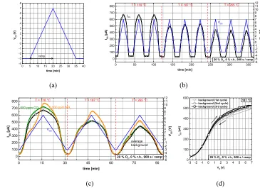
In order to study hysteresis curves the gate bias was lin-early ramped up from −3 V to +7 V and back down again over 900 s each (Fig. 3a). Before and after these ramps, the potential was kept constant at−3 V for 300 s (in back-ground) or 30 s (in test gas) each. This cycle was repeated three times at each temperature in background as shown in Fig. 3b. One cycle was run at each temperature in every test gas (Fig. 3c).Temperature changes were only made between two cycles, thus, the device was given sufficient time to reach equilibrium before a new gate bias ramp was started. Before each measurement series, i.e., gas composition change, the
sensor was run in background only for at least one hour, and subsequently in the investigated gas composition until the baseline had stabilized.
Additionally, the influence of the bias sweep rate was stud-ied by testing ramps with a duration of 300 s and 60 s, respec-tively. Varying sweep rates offer the possibility to estimate time constants of phenomena involved in the sensor response mechanisms, possibly providing information helpful in the separation of different, competing effects.
2.3 Data evaluation
The recorded raw signals plotted vs. the applied gate bias VGS are shown in Fig. 4a and c for two different temperatures. In order to suppress the sensor signal variation in the back-ground gas, which actually shows nearly no hysteresis, and to enhance the gas induced signal changes the difference signal
∆IDS=IDS(gas)−IDS(background) is used for further analy-sis (Fig. 4b, d). The background signal was determined from the mean value of three gate bias cycle measurements. Al-though the first cycle usually shows slightly lower values, the background cycles exhibit negligible variations thus showing good overall reproducibility (Fig. 3d). The same applies to background cycles recorded after and, respectively, between test gas exposures.
To discriminate different gases, a relatively fast cycle is run several times in each of the examined atmospheres, and pre-defined features are calculated for every cycle. The obtained multi-dimensional data of the so-called virtual multi-sensor (Schütze et al., 2004) is usually evaluated by pattern recog-nition tools. Instead of the often used principal component analysis (PCA, un-supervised learning), here linear discrim-inant analysis (LDA) was employed as a powerful tool for evaluation of multivariate data. LDA is a supervised learning method, which means that the correct classification is known for each object, i.e., cycle (Gutierrez-Osuna, 2002; Klecka, 1980). With this method, it is possible to determine whether
18
0 5 10 15 20 25 30 35 40
-4 -3 -2 -1 0 1 2 3 4 5 6 7 8
VGS
[
V
]
time [min]
ramp
0 50 100 150 200 250 300 350
0 100 200 300 400 500 600 700
800 T = 187 °C T = 265 °C
IDS
[
µ
A]
time [min]
T = 118 °C
-6 -5 -4 -3 -2 -1 0 1 2 3 4 5 6 7 8 9 10 11 12
20 % O2, 0 % r.h., 900 s / ramp
IDS
VGS
VGS
[
V
]
(a) (b)
0 15 30 45 60 75 90
0 100 200 300 400 500 600 700 800
20 % O2, 0 % r.h., 900 s / ramp
IDS
[ µ A ] time [min] -6 -5 -4 -3 -2 -1 0 1 2 3 4 5 6 7 8 9 10 11 12 VGS average background
500 ppm CO 500 ppm NH3
T = 265 °C T = 187 °C
VG
S
[
V
]
T = 118 °C
-3 -2 -1 0 1 2 3 4 5 6 7 0 100 200 300 400 500 600
background (1st cycle) background (2nd cycle) background (3rd cycle)
IDS
[
µ
A
]
VG [V]
187 °C
20 % O2, 0 % r.h., 900 s / ramp
(c) (d)
1
Figure 3. Visualization of a gate bias cycle (a), an excerpt from an actual measurement 2
showing the gate potential (blue) and sensor response (black) at three different temperatures 3
in background (black, rectangles) (b) and with ammonia (orange, circle) or CO (green, 4
triangles) (c), and the absolute signal of three cycles in background (d). One hysteresis curve 5
consists of one ramp up and one ramp down. 6
7
Figure 3.Visualization of a gate bias cycle (a), an excerpt from an actual measurement showing the gate potential (blue) and sensor response (black) at three different temperatures in background (black, rectangles) (b) and with ammonia (orange, circle) or CO (green, triangles) (c), and the absolute signal of three cycles in background (d). One hysteresis curve consists of one ramp up and one ramp down.
the gas-induced changes in the hysteresis shape are sufficient, i.e., distinct enough and also reproducible, to achieve a non-ambiguous classification of the different gases.
In order to describe the shape of a hysteresis generally some easily computable features were defined: the largest horizontal and vertical widths of the hysteresis, the position of these maxima, as well as the area enclosed by the curve (cf. Fig. 12b).
3 Results and discussions
3.1 Gas discrimination
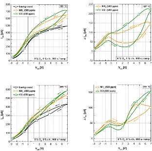
The measured data show that the shape of the hysteresis sig-nal of a GasFET is a suitable feature for gas discrimination. The gases can be clearly distinguished from background as well as from each other based on the shape of the hystere-sis curves (Fig. 4a, c). After subtraction of the background signal, a peak becomes evident for CO and NH3 (Fig. 4b), which appears around 0 V. Thus, it can be interpreted as a polarity dependent effect, e.g., the flipping of trap states, as postulated by Paska and Haick (2012), or the movement of mobile oxide charges. The transfer characteristics inherent to the device (as discussed in the last paragraph in Sect. 3.4) could contribute to the observed peak as well. At 265◦C, this peak is even more distinct and the hysteresis width is smaller, especially for CO, than at 187◦C (Fig. 4d).
More-over, a crossover point appears for both gases around 2.5 V, which indicates that there are two different and competing processes, e.g., surface reactions and/or diffusion, influenc-ing the sensor signal.
Figure 5a shows the hysteresis with background subtracted for NO and CH4at 187◦C sensor temperature. Comparison with Fig. 4b reveals obvious differences in the signal shapes of all four gases, thus allowing identification of all four gases. No peaks appear around the 0 V gate bias for NO and CH4; instead, a change in slope is observed for NO, while CH4 shows a crossover point of the signals for ramp up and ramp down. Regarding the sensor temperature (cf. Fig. 5a and b), a similar change as for CO and NH3 can be observed: at 265◦C, the difference signal∆I
DS and, thus, the sensitivity are reduced. A significant sensor response is only observed for a gate bias above 3 V. Crossover points are now observed for both gases, although at different gate bias voltages, while the hysteresis width again decreases.
3.2 Influence of oxygen and humidity
Figure 6 shows the sensor signals ∆IDS for CO and NH3 in dry air, i.e., at 20 % oxygen (O2), in Fig. 7 at 50 % RH in pure nitrogen, and in Fig. 8 in humid air, i.e., with 20 % O2 plus 50 % RH. All three figures also show sig-nificant signal changes resulting from an increase of the
Figure 4.The absolute sensor response (a, c) and the difference signal vs. background ∆IDS=IDS(gas)−IDS(background) (b, d) for a
background of dry nitrogen (black, rectangles) as well as 500 ppm ammonia (orange, circles) and 500 ppm CO (green, triangles) at 187◦
C
(a, b) and 265◦
C (c, d).
-3 -2 -1 0 1 2 3 4 5 6 7
-50 -25 0 25 50 75 100
0 % O2, 0 % r.h., 900 s / ramp
NO1 (500 ppm)
CH4 (500 ppm)
187 °C
∆
IDS
[
µ
A
]
VGS [V]
-3 -2 -1 0 1 2 3 4 5 6 7
-50 -25 0 25 50 75 100
265 °C
0 % O2, 0 % r.h., 900 s / ramp
NO1 (500 ppm)
CH4 (500 ppm)
∆
IDS
[
µ
A
]
VGS [V]
(a) (b)
1
Figure 5. Hysteresis of ΔIDS for 500 ppm NO (red, triangles) and CH4 (purple, diamonds) in
2
dry nitrogen at 187 °C (a) and 265 °C (b). 3
4
Figure 5.Hysteresis of∆IDSfor 500 ppm NO (red, triangles) and CH4(purple, diamonds) in dry nitrogen at 187◦C (a) and 265◦C (b).
21
-3 -2 -1 0 1 2 3 4 5 6 7
-50 -25 0 25 50 75 100 125 150
20 % O2, 0 % r.h., 900 s / ramp
187 °C
∆
IDS
[
µ
A
]
VGS [V]
NH3 (500 ppm)
CO1(500 ppm)
-3 -2 -1 0 1 2 3 4 5 6 7
-50 -25 0 25 50 75 100 125 150
20 % O2, 0 % r.h., 900 s / ramp
265 °C
∆
IDS
[
µ
A
]
VGS [V]
NH3 (500 ppm)
CO1(500 ppm)
(a) (b)
1
Figure 6. Hysteresis of ΔIDS for CO (green, triangles) and NH3 (orange, circles) in dry air
2
(20 % O2, 0 % r.h.) at 187 °C (a) and 265 °C (b).
3
4
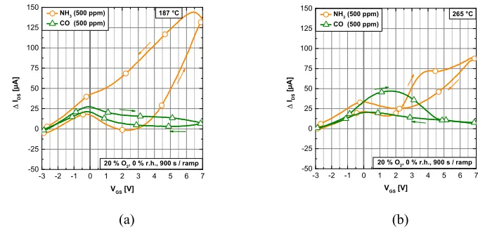
Figure 6.Hysteresis of∆IDSfor CO (green, triangles) and NH3(orange, circles) in dry air (20 % O2, 0 % RH) at 187◦C (a) and 265◦C (b).
22
-3 -2 -1 0 1 2 3 4 5 6 7
-50 0 50 100 150 200
0 % O2, 50 % r.h., 900 s / ramp
187 °C
∆
IDS
[
µ
A
]
VGS [V]
NH3 (500 ppm)
CO (500 ppm)1
-3 -2 -1 0 1 2 3 4 5 6 7
0 50 100 150
0 % O2, 50 % r.h., 900 s / ramp
265 °C
∆
IDS
[
µ
A
]
VGS [V]
NH3 (500 ppm)
CO (500 ppm)
(a) (b)
1
Figure 7. Hysteresis of ΔIDS for CO (green, triangles) and NH3 (orange, circles) in pure
2
nitrogen at 50 % r.h. at 187 °C (a) and 265 °C (b). 3
4
Figure 7.Hysteresis of∆IDSfor CO (green, triangles) and NH3(orange, circles) in pure nitrogen at 50 % RH at 187◦C (a) and 265◦C (b).
operating temperature from 187◦C (Figs. 6a, 7a, 8a) to 265◦C (Figs. 6b, 7b, 8b).
Background oxygen strongly influences the CO signal while it has little effect on the NH3 response (cf. Figs. 4b and 6a as well as 8a). This could be expected since CO as a very reactive reducing gas interacts with negatively charged oxygen ions on the sensor surface. At either low temperatures or a high CO/O2ratio, the Pt surface is completely reduced, i.e., no adsorbed oxygen is present, whereas it is almost com-pletely covered with adsorbed oxygen for high temperatures or a low CO/O2ratio (Johansson et al., 2001). Thus, in the presence of 20 % O2the equilibrium coverage of CO on the sensor surface is small, hence both the sensor signal as well as the hysteresis width decrease strongly (Fig. 6a). However, CO can still be detected due to the peak around the 0 V gate bias.
In contrast, the hysteresis width decreases strongly for NH3in the presence of humidity while the CO signal remains largely unchanged (cf. Figs. 4b and 7a). In addition, the 0 V peak for NH3vanishes almost completely.
With both oxygen and humidity present in the background, the change in the signal shape upon CO exposure seems to be dominated by the influence of oxygen at 187◦C and 265◦C (cf. Figs. 4 and 7 as well as 6 and 8, respectively). The effect of background on the NH3response is more complicated: at 187◦C, the hysteresis width in humid air is smaller than in dry nitrogen, which is similar to the response in humid nitro-gen; in addition, the peak around 0 V, which is not observed in humid nitrogen, is very pronounced (Fig. 8a). At 265◦C, in addition to a slightly smaller hysteresis width compared to dry oxygen, no clear crossover point is seen, which only happens in this background (Fig. 8b).
The sensor temperature is another parameter that can be used to alter the shape of the hysteresis drastically. Figures 6b and 7b show the same measurements as in Figs. 6a and 7a, respectively, but with a sensor temperature of 265◦C instead of 187◦C. As an overall effect for the gases and temperature range investigated here, higher temperature leads to lower signals and, thus, lower sensitivity. Nakagomi et al. (2005) reported that this effect can be compensated by a positive
23
-3 -2 -1 0 1 2 3 4 5 6 7
-25 0 25 50 75 100
20 % O2, 50 % r.h., 900 s / ramp
187 °C
∆
IDS
[
µ
A
]
VGS [V]
NH3 (500 ppm)
CO (500 ppm)
-3 -2 -1 0 1 2 3 4 5 6 7
0 25 50 75 100
20 % O2, 50 % r.h., 900 s / ramp
265 °C
∆
IDS
[
µA
]
VGS [V]
NH3 (500 ppm)
CO (500 ppm)
(a) (b)
1
Figure 8. Hysteresis of ΔIDS for CO (green, triangles) and NH3 (orange, circles) in humid air
2
(20 % O2, 50 % r.h.) at 187 °C (a) and 265 °C (b).
3
4
Figure 8.Hysteresis of∆IDSfor CO (green, triangles) and NH3(orange, circles) in humid air (20 % O2, 50 % RH) at 187◦C (a) and 265◦C
(b).
0 50 100 150
-3 -2 -1 0 1 2 3 4 5 6 7
0 50 100 150
500 ppm
∆
IDS
[
µ
A
]
NH3
CO1
187 °C
0 % O2, 0 % r.h., 300 s / ramp
∆
IDS
[
µ
A
]
VGS [V]
250 ppm
0,0 0,2 0,4 0,6 0,8
-3 -2 -1 0 1 2 3 4 5 6 7
0,0 0,2 0,4 0,6 0,8
12%
500 ppm
0 % O2, 0 % r.h., 300 s / ramp
∆
IDS
/
IDS
,
g
a
s
NH3
CO1
187 °C 22%
250 ppm
∆
IDS
/
IDS
,
g
a
s
VGS [V]
5% 7%
(a) (b)
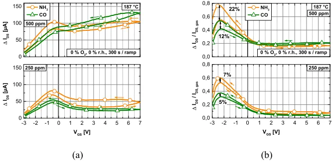
1
Figure 9. Influence of the gas concentration on the hysteresis in difference signal (a) and in 2
difference signal relative to the absolute signal in gas (b). 3
4
Figure 9.Influence of the gas concentration on the hysteresis in difference signal (a) and in difference signal relative to the absolute signal in gas (b).
gate bias. In addition, there is a strong change of the signal shape, resulting in greater differences between the gases, i.e., improved selectivity. At this higher temperature, a stronger hysteresis is detected for CO in air at moderate gate bias val-ues (0–4 V, Figs. 6b, 8b). More significantly, crossover points appear in the hysteresis for NH3 in dry air (Fig. 6b) and for both gases in nitrogen (Figs. 4d, 7b). The position of these crossover points can be used as an additional feature for gas discrimination. They also indicate that two competing pro-cesses with different time constants and temperature depen-dence are occurring on the sensor surface or, more likely, due to the long time constants, which indicate diffusion processes in the sensor layers, e.g., moving charges in the gate oxide.
25
-3 -2 -1 0 1 2 3 4 5 6 7
-200 -150 -100 -50 0 50 100 150
CO (500 ppm)
118 °C
0 % O2, 0 % r.h.
∆
IDS
[
µ
A
]
VGS [V]
900 s / ramp 300 s / ramp 30 s / ramp
-3 -2 -1 0 1 2 3 4 5 6 7
0 50 100 150
CO (500 ppm)
∆
IDS
[
µ
A
]
VGS [V]
900 s / ramp 300 s / ramp 30 s / ramp
265 °C
0 % O2, 0 % r.h.
(a) (b)
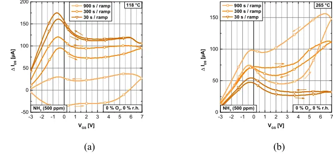
1
Figure 10. Hysteresis for CO (500 ppm) in dry nitrogen at 118 °C (a) and 265 °C (b) for 2
different ramp durations (rectangles: 900 s; circles: 300 s; triangles: 30 s). 3
4
Figure 10.Hysteresis for CO (500 ppm) in dry nitrogen at 118◦
C (a) and 265◦C (b) for different ramp durations (rectangles: 900 s; circles:
300 s; triangles: 30 s).
26
-3 -2 -1 0 1 2 3 4 5 6 7
-50 0 50 100 150 200
NH3 (500 ppm)
∆
IDS
[
µ
A
]
VGS [V]
900 s / ramp 300 s / ramp 30 s / ramp
118 °C
0 % O2, 0 % r.h.
-3 -2 -1 0 1 2 3 4 5 6 7
0 50 100 150
NH3 (500 ppm)
∆
IDS
[
µ
A
]
VGS [V]
900 s / ramp 300 s / ramp 30 s / ramp
265 °C
0 % O2, 0 % r.h.
(a) (b)
1
Figure 11. Hysteresis for NH3 (500 ppm) in dry nitrogen at 118 °C (a) and 265 °C (b) for
2
different ramp durations (rectangle marker 900 s, circle marker 300 s, triangle marker 30 s). 3
4
Figure 11.Hysteresis for NH3(500 ppm) in dry nitrogen at 118◦C (a) and 265◦C (b) for different ramp durations (rectangle marker 900 s,
circle marker 300 s, triangle marker 30 s).
3.4 Influence of the gate bias sweep rate
Obviously, a strong influence of the cycle duration, i.e., the gate bias ramp rate, on the hysteresis could be expected as this is evidence that the sensor is not in equilibrium. Thus, in addition to measurements lasting 30 min (1800 s correspond-ing to a ramp rate of 10 V/900 s=11.1 mV s−1) per cycle, shorter cycle durations, i.e., faster bias ramp rates, of 600 s (33.3 mV s−1) and 60 s (333 mV s−1) were evaluated to study the potential of this method for realistic application scenarios requiring shorter response times as shown in Figs. 10 and 11 for CO and NH3, respectively.
A significant change in the hysteresis shape is observed for shorter cycles, which is another indication of the pres-ence of at least two processes with different time constants. A good example for this effect is the observed behavior for CO at 118◦C (Fig. 10a), where the signal becomes negative for the 900 s ramp, but positive during the 300 s ramp. For the 30 s ramp, the signal change is relatively small compared
to the two other cases, i.e., almost zero except for a small peak around 0 V, indicating that the processes on the sensor surface at this temperature are too slow to lead to a signifi-cant signal change. However, the hysteresis width is highest for the fast ramp, indicating a strong nonequilibrium condi-tion. At the higher sensor temperature of 265◦C (Fig. 10b), the signal continuously decreases for increasing sweep rates; however, the hysteresis is again more pronounced for the higher ramp rates. Furthermore, the signal is positive for ev-ery sweep rate tested; however, a crossover point appears only for the slow 900 s ramp. This indicates an underlying process, either surface reactions or – more likely – diffusion, with a time constant between 300 s and 900 s, which is only observed during the long cycle.
For NH3at 118◦C (Fig. 11a) the hysteresis width is small at high sweep rates, contrary to the behavior observed for CO. The 30 s ramp, which produced nearly no signal for CO, shows the highest signal of all tested ramps for NH3, indicat-ing that the process responsible for the NH3response is fast
0 10 20 30 40 50 60 -3
-2 -1 0 1 2 3 4 5 6
Treal
Tset
VG
S
[
V
]
time [s]
VGS
230 240 250 260 270 280 290 300 310 320
te
m
p
e
ra
tu
re
[
°C
]
-2 -1 0 1 2 3 4 5
100 200 300 400
300 °C
0 % O2, 0 % r.h., 777 mV / s
CO (500 ppm)
IDS
[µ
A
]
VGS [V]
(a) (b)
-30 -20 -10 0 10
-3 -2 -1 0 1 2
3 250 / 300 °C
0 % O2, 0 % r.h., 777 mV / s
dry nitrogen0
NH3 (500 ppm)
CO (500 ppm)
2
n
d
d
is
c
ri
m
in
a
n
t
fu
n
c
ti
o
n
(
0
.1
1
%
)
1st discriminant function (99.89 %)
(c)
1
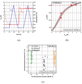
Figure 12. Combined TCO-GBCO cycle (a). Features that can be extracted from a hysteresis 2
curve: the maximum horizontal and vertical width (red arrows), the position of these maxima 3
(red dots) and the area enclosed by the curve (light red) (b). LDA discrimination between dry 4
nitrogen (background), CO and ammonia based on hysteresis features (horizontal and vertical 5
width and area) from 9 s ramps (from –2 to 5 V, i.e. 777 mV/s) at 250 and 300 °C plus the 6
signal mean value over the interval 0 to 10 s of the cycle (c). 7
Figure 12.Combined TCO–GBCO cycle (a). Features that can be extracted from a hysteresis curve: the maximum horizontal and vertical width (red arrows), the position of these maxima (red dots) and the area enclosed by the curve (light red) (b). LDA discrimination between dry nitrogen (background), CO and ammonia based on hysteresis features (horizontal and vertical width and area) from 9 s ramps (from−2 V to 5 V, i.e., 777 mV s−1) at 250◦
C and 300◦
C plus the signal mean value over the interval of 0–10 s of the cycle (c).
even at this low temperature in an atmosphere of 0 % O2and 0 % RH. The main cause of the sensor signal observed here is probably NH3adsorption on Pt (Wallin et al., 2004), which is favored over O2adsorption, and consecutive spillover of NH3 to the oxide, thus replacing oxygen anions with polar NH3 molecules. This is also supported by Fogelberg et al. (1987),
118◦C. Presumably, this behavior is again caused by at least two competing effects with different time constants.
Another effect becomes obvious when comparing
(or both). An increased gate bias could for example lead to stronger binding of electrons in the metal, i.e., a higher energy barrier for the formation of oxygen ions, and/or a change in the equilibrium spillover of oxygen anions from the metal to the silicon dioxide surface.
3.5 Combination of temperature and gate bias cycle
Shorter cycles (up to one minute) are required to use the presented method in practical applications similar to tem-perature cycled operation (TCO). As the hysteresis becomes more distinct for higher sensor temperatures, this can be ex-ploited to achieve shorter cycle times. A simple T cycle con-sisting of two temperature plateaus (250◦C and 300◦C), each 30 s long, was chosen to obtain higher sensitivity (Bur et al., 2012b) and faster response. After 10 s on each plateau to reach a steady temperature the gate bias was cycled from
−2 V to 5 V and back within 9 s per ramp, corresponding to a ramp rate of 777 mV s−1, as shown in Fig. 12a. This one-minute cycle is suitable to achieve a very clear discrimina-tion of background (dry nitrogen), 500 ppm CO and 500 ppm NH3, using LDA. The LDA plot shown in Fig. 12c was cal-culated using only the vertical and horizontal (absolute) max-imum width, the areas enclosed by the two hysteresis curves and the signal mean value between 0 s and 10 s of the cycle, i.e., a total of seven features, three each for both tempera-ture plateaus and the mean value. The plot shows a total of 136 cycles, thus the number of features is much lower than the number of samples to avoid overfitting. Note that the dis-crimination would probably also be possible for lower con-centrations as the two gases show a shift in opposite direc-tions from the background.
To extend this approach to hysteresis curves with one or more crossover points, several amendments would be possi-ble. First, additional determination of the negative and pos-itive maximum widths, both horizontally and vertically, as well as their positions provides information about the exis-tence of a crossover point, as the difference will change its sign after a crossover point. If more than one crossover point is present, the algorithm must be executed on distinct ranges of the curve that are defined by the position of the crossover points to determine the width of each individual loop. Addi-tionally, the position of the crossover points themselves could be considered as features for signal evaluation.
4 Conclusions
We have shown that hysteresis induced by cyclic changes of the gate bias can be used very effectively to increase the se-lectivity of SiC gas sensitive field effect transistors allowing identification of NH3, CO, NO and CH4 even in changing background compositions, i.e., dry and humid nitrogen and air. Furthermore, quantification by taking the width of the hysteresis into account is possible as shown for NH3 and CO. Changes in the background gas mixture lead to strong
changes in the shape of the signal; however, gases can still be identified.
The sweep rate of the applied gate bias ramp also has a strong influence on the signal shape that is strongly depen-dent on the gas and the sensor temperature. In any case, dif-fusion processes in the sensor and also chemical reactions on the sensor surface are accelerated at higher operating tem-perature, thus increasing the signal hysteresis and allowing one full measurement per minute. Easily computable features have been suggested and their application was demonstrated in a LDA to discriminate 500 ppm CO, NH3 and dry nitro-gen.
Future work will address the optimization of the GBCO technique both as stand-alone method as well as in combi-nation with TCO to allow improved qualitative as well as quantitative measurements. This includes both the efficient determination of the optimum operating cycle for a given ap-plication as well as the optimum signal evaluation, i.e., ob-taining the maximum information with the minimum of ef-fort. Especially gas mixtures and dynamic gas composition changes need to be addressed if this approach is to be used in real applications, but also the signal stability needs to be taken into account.
Finally, the presented method of studying the sensor re-sponse can help to achieve a better understanding of gas in-teraction on and signal generation in GasFETs as the dy-namic operation allows studying different effects on and in the sensor by choosing different temperatures and bias ramp rates to identify and separate different effects.
Acknowledgements. The authors would like to thank SenSiC
AB, Kista, Sweden, for providing the sensors and 3S - Sensors, Signal Processing, Systems GmbH, Saarbrücken, Germany, for providing the hardware for sensor operation and read-out.
Edited by: M. Penza
Reviewed by: two anonymous referees
References
Andersson, M., Pearce, R., and Lloyd Spetz, A.: New generation SiC based field effect transistor gas sensors, Sens. Actuators B., 179, 95–106, 2013.
Bastuck, M., Bur, C., Lloyd Spetz, A., Andersson, M., and Schütze, A.: Identification of ammonia and carbon monoxide based on the hysteresis of a gas-sensitive SiC field effect transistor, Proc. Transducers 2013, Barcelona, Spain, 2013.
Bur, C., Andersson, M., Lloyd Spetz, A., and Schütze, A.: Influence of a changing gate bias on the sensing properties of SiC field effect gas sensors, Proc. IMCS 2012, Nuremberg, Germany, 140– 143, 2012a.
Bur, C., Reimann, P., Andersson, M., Schütze, A., and Lloyd Spetz, A.: Increasing the selectivity of Pt-gate SiC field effect gas sen-sors by dynamic temperature modulation, IEEE Sensen-sors Journal, 12, 1906–1913, 2012b.
Bur, C., Bastuck, M., Andersson, M., Lloyd Spetz, A., and Schütze, A.: Combination of Temperature Cycled And Gate Bias Cycled Operation To Enhance the Selectivity of SiC-FET Gas Sensors, Proc. Transducers 2013, Barcelona, Spain, 2041–2044, 2013. Darmastuti, Z., Pearce, R., Lloyd Spetz, A., and Andersson, M.:
The influence of gate bias and structure on the CO sensing per-formance of SiC based field effect sensors, Proc. IEEE Sensors 2011, Limerick, Ireland, 133–136, 2011.
Fogelberg, J., Lundström, I., and Petersson, L.-G.: Ammonia Disso-ciation on Oxygen Covered Palladium studied with a Hydrogen Sensitive Pd-MOS device, Physica Scripta, 35, 702–705, 1987. Gutierrez-Osuna, R.: Pattern Analysis for Machine Olfaction: A
Re-view, IEEE Sensors Journal, 2, 189–202, 2002.
Johansson, S., Österlund, L., and Kasemo, B.: CO oxidation bista-bility diagrams for Pt/CeOx and Pt/SiO2 model catalysts pre-pared by electron-beam lithography, Journal of Catalysis, 201, 275–285, 2001.
Klecka, W. R.: Discriminant Analysis, in Quantitative applica-tions in the social sciences, SAGE University Paper, ISBN: 0803914911, 1980.
Lee, A. P. and Reedy, B. J.: Temperature modulation in semicon-ductor gas sensing, Sens. Actuators B, 60, 35–42, 1999. Lloyd Spetz, A., Huatari, J., Bur, C., Bjorklund, R., Lappalainen, J.,
Jantunen, H., Schütze, A., and Andersson, M.: Chemical sensor systems for emission control from combustions, Sens. Actuators B, 187, 184–190, 2013.
Lundström, I, Sundgren, H., Winquist, F., Eriksson, M., Krantz-Rülcker, C., and Lloyd Spetz, A.: Twenty-?ve years of field effect gas sensor research in Linköping, Sens. Actuators B., 121, 247– 262, 2007.
Mattmann, M., Helbling, T., Durrer, L., Roman, C., Pohle, R., Fleis-cher, M., and Hierold, C.: Hysteresis reduction and measure-ment range enhancemeasure-ment of carbon nanotube based NO2gas
sen-sors by pulsed gate voltages, Procedia Chemistry, 1, 1431–1434, 2009.
Nakagomi, S., Tobias, P., Baranzahi, A., Lundström, I., Mårtensson, P., and Lloyd Spetz, A.: Influence of carbon monoxide, water and oxygen on high temperature catalytic metal-oxide-silicon carbide structures, Sens. Actuators B, 45, 183–191, 1997.
Nakagomi, S., Fukumura, A., Kokubun, Y., Savage, S., Wingbrant, H., Andersson, M., Lundström, I., Löfdahl, M., and Lloyd Spetz, A.: Influence of gate bias of MISiC-FET gas sensor device on the sensing properties, Sens. Actuators B, 108, 501–507, 2005. Paska, Y. and Haick, H.: Interactive effect of hysteresis and
sur-face chemistry on gated silicon nanowire gas sensors, ACS Appl. Mater. Interfaces, 4, 2604–2617, 2012.
Petit, C., Zander, D., Lmimouni, K., Ternisien, M., Tondelier, D., Lenfant, S., and Vuillaume, D.: Gate pulse electrical method to characterize hysteresis phenomena in organic field effect transis-tor, Org. Electron., 9, 979–984, 2008.
Schalwig, J., Kreisl, P., Ahlers, S., and Müller, G.: Response mech-anism of SiC-based MOS field-effect gas sensors, IEEE Sensors Journal, 2, 394–402, 2002.
Schmidt-Zhang, P., Sandow, K.-P., Adolf, F., Göpel, W., and Guth, U.: A novel thick film sensor for simultaneous O2and NO
mon-itoring in exhaust gases, Sens. Actuators B, 70, 25–29, 2000. Schütze, A., Gramm, A., and Rühl, T.: Identification of organic
sol-vents by a virtual multisensor system with hierarchical classifi-cation, IEEE Sensors Journal, 4, 857–863, 2004.
Wallin, M., Grönbeck, H., Lloyd Spetz, A., and Skoglundh, M.: Vi-brational study of ammonia adsorption on Pt/SiO2, Appl. Surf.