www.mech-sci.net/7/39/2016/ doi:10.5194/ms-7-39-2016
© Author(s) 2016. CC Attribution 3.0 License.
A representation of the configurations and evolution of
metamorphic mechanisms
W. Zhang1,2, X. Ding1, and J. Liu2
1School of Mechanical Engineering and Automation, Beihang University, Beijing, China 2State Key Laboratory of Robotics, Shenyang Institute of Automation, Chinese Academy of Sciences,
Shenyang, China
Correspondence to: W. Zhang ([email protected])
Received: 7 June 2015 – Revised: 5 January 2016 – Accepted: 6 January 2016 – Published: 9 February 2016 Abstract. Metamorphic mechanisms are members of the class of mechanisms that are able to change their con-figurations sequentially to meet different requirements. The paper introduces a comprehensive symbolic matrix representation for characterizing the topology of one of these mechanisms in a single configuration using gen-eral information concerning links and joints. Furthermore, a matrix representation of an original metamorphic mechanism that has the ability to evolve is proposed by uniting the matrices representing all of the mechanism’s possible configurations. The representation of metamorphic kinematic joints is developed in accordance with the variation laws of these mechanisms. By introducing the joint variation matrices derived from generalized operations on the related symbolic adjacency matrices, evolutionary relationships between mechanisms in ad-jacent configurations and the original metmaorphic mechanism are made distinctly. Examples are provided to demonstrate the validation of the method.
1 Introduction
In contrast to a traditional mechanism, a metamorphic mech-anism is a mechmech-anism with variable topological structures and it is a good approach for resolving the contradiction between economy, adaptation and efficiency. The concept of metamorphic mechanisms was first introduced based on the idea of reconfiguration in 1996 by Jian S. Dai and Rees Jones, which led to a new era of modern mechanism development (Dai and Rees Jones, 1998).
Research on the metamorphic mechanism has been mak-ing significant improvements in fundamentals and applica-tions for nearly twenty years. The essence and character-istics of metamorphic mechanisms as well as three meta-morphic approaches including variable components, adja-cent relations and kinematic joints were introduced by Dai et al. (2005a) and Liu and Yang (2004). In addition, some of the basic constituent elements of these mechanisms, including links and their connectivity relationships, remain unchanged to give the mechanism’s adjacent configuration complex cou-pling features. These two aspects are key factors affecting the study of methods for configuring metamorphic mechanisms
(Zhang et al., 2011). Therefore, to create topological varia-tions in the characteristics of mechanisms in different config-urations, the appropriate structural representation for a meta-morphic mechanism has been researched in recent years.
re-configurable mechanisms. These matrices can be used as an analysis tool to automatically determine the degrees of free-dom of planar mechanisms that only contain one degree of freedom (DOF) joint. Herve (2006) showed how to create translational parallel manipulators using Lie-group algebra, which can give reference to the related research. Yan and Kang (2009) showed how to perform configuration synthesis of mechanisms with variable topologies using graph theory.
However, the axial orientation of a joint and information on link variations were not epitomized in the aforementioned research. Therefore, Yang (2004) introduced the concept of a geometric constraint for expressing the relative positions and orientations of the joint axes and generalized it into six types: parallelism, coincidence, intersection, perpendicular-ity, coplanarity and randomness. Li et al. (2010) suggested using a constraint graph from computational geometry rather than the traditional topological graph to characterize a meta-morphic linkage to simplify the representation of its config-uration changes. The adjacency submatrix of the constraint graph provides a convenient description of changes in the topology of links and joints in the operation of the metamor-phic linkage. Li et al. (2009) and Li and Dai (2010a, b) devel-oped a topological representation matrix with information on loops, types of links and joints that included orientation in-formation, which has been used in subsequent research. They also introduced a joint-orientation interchanging metamor-phic method based on the matrix.
This paper presents a novel method of characterizing the topology of metamorphic mechanisms in all configurations that involves information about links and joints, including their types and axial orientations. Furthermore, a method of constructing an original matrix that represents the original metamorphic mechanism is proposed. Next, the paper pro-poses two matrix operations that are useful for representing topological changes and evolving features.
2 Configuration characteristics of metamorphic mechanisms
A metamorphic mechanism is a mechanism with variable topological structures that can be transformed from one structure to another continuously. There are variable parts and coupling parts, giving the metamorphic mechanism a variable topological structure and coupling relationship. In particular, variability is the distinguishing feature that sepa-rates metamorphic mechanisms from common mechanisms; this is an important area of research. The incorporation of links, the changing relationships of adjacent links and the changing properties of kinematic pairs have been explored to summarize the variable features of metamorphic mecha-nisms. In essence, a metamorphic kinematic joint is the es-sential prerequisite for changing the number of and connec-tive relationships among its acconnec-tive links, leading to a
transfor-mation of the configuration of the entire mechanism (Zhang et al., 2011).
An example of a planar five-bar metamorphic linkage which has five configurations is shown in Fig. 1. Transforma-tions between them are performed by locking different kine-matic joints sequentially. When the mechanism is in configu-ration 1, as shown in Fig. 1a, slidercis locked at the top end of the slot in linkd. In this configuration, the mechanism can be treated as a four-bar mechanism. When the mechanism is in configuration 2, as shown in Fig. 1b, linksaandbare fixed together by locking the revolute jointBas well as slidercand linkdare unlocked. Therefore the mechanism is transformed into a guide bar mechanism. When revolute jointCis locked, linksbandcare fixed to transform mechanism into another guide bar mechanism, as shown in Fig. 1c. When the mecha-nism is in configuration 4, linksaandeare fixed together by locking revolute jointA, as shown in Fig. 1d. Linkbbecomes the driving link of the mechanism. When linkdarrives at the location shown in Fig. 1e, jointD is locked to fix linksd
ande. This transforms mechanism into a crank slider mecha-nism. Therefore, the mechanism realizes transformations be-tween different configurations by locking its kinematic joints in particular sequences.
From Fig. 1, we conclude that the structure of the mech-anism can be transformed from one to another by locking different kinematic joints accordingly. By applying modes such as the geometric limit, force limit, and variation of the driving kinematic joint, the working conditions of these kinematic joints can be switched between active and locked states. In addition, metamorphic kinematic joints are able to change their types and motion orientations to realize config-uration transformations (Yan and Kuo, 2006). In a metamor-phic mechanism, there is at least one metamormetamor-phic kinematic joint, which can change the number and connectivity rela-tionships of active links. There are some basic constituent el-ements, including links and their connectivity relationships, which remain unchanged to create complex coupling fea-tures among the links in adjacent configurations, as shown in Fig. 1.
Therefore, to understand the configuration characteristics of metamorphic mechanisms, it is necessary to present a con-figuration representation that can express not only the charac-teristics of the mechanism in all of its configurations but also the variations during the transformation process intuitively with the help of specific operations.
3 Representing the configurations of metamorphic mechanisms
It is known that an adjacency matrix can be used to represent the topological structures of metamorphic mechanisms. This matrix and an EU-elementary matrix operation were intro-duced for expressing a configuration transformation (Dai et al., 2005b; Dai and Rees Jones, 2005). Furthermore, a
A
B C D a b c d e(locked)
z
y
(a) The mechanism in configuration 1
A
(locked)B
D a b c d e C y z
(b) The mechanism in configuration 2
A
B C D a b c d e(locked)
y z
(c) The mechanism in configuration 3
(locked)
A a e D B C b c d y z
(d) The mechanism in configuration 4
A
a e
C
(locked)
D c d B b y z (e) The mechanism in configuration 5
Figure 1.A five-bar planar metamorphic linkage.
bolic adjacency matrix was constructed by introducing infor-mation on link variations and joint orientations (Li and Dai, 2010a; Zhang and Ding, 2012). The variations and coupling features of the metamorphic mechanism in adjacent configu-rations can be determined by applying the generalized differ-ence and intersection operations to the corresponding sym-bolic matrices.
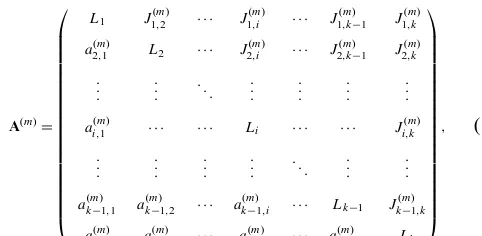
However, the matrices representing mechanisms in differ-ent configurations do not have the same dimension and need to be normalized, increasing the complexity of the represen-tation and operations. Simultaneously, the upper off-diagonal elements in the matrix are the same as the lower off-diagonal elements, which means that the matrix contains information in duplicate. Therefore, to decrease the complexity of ex-pressing the matrix and subsequent operations on it, we im-prove the symbolic matrix for the mechanism in configura-tionmand express it as follows:
A(m)=
L1 J1(m,2) · · · J (m)
1,i · · · J
(m) 1,k−1 J
(m) 1,k
a2(m,1) L2 · · · J2(m,i) · · · J
(m) 2,k−1 J
(m) 2,k . . . . . . . .. . . . . . . . . . . . .
ai,(m1) · · · Li · · · Ji,k(m)
. . . . . . . . . . . . . .. ... . . .
a(km−)1,1 a (m)
k−1,2 · · · a (m)
k−1,i · · · Lk−1 Jk(m−)1,k
ak,(m1) a(k,m2) · · · ak,i(m) · · · ak,k(m)−1 Lk
, (1)
where the principal diagonal elementLi represents the link
whose sequence number in the mechanism isi. The numbers of rows and columns are bothk, which indicates the num-ber of links in all configurations. Normally,kis greater than or equal to the maximum number of effective links in every configuration. The upper off-diagonal elementJi,j(m)denotes the connectivity relationship between linksLi andLj. It can
be represented by a symbol with subscript where the symbol denotes the joint type and the subscript expresses the geo-metric constraint relationship of the joint axes located at the ends of the link. It is noted that the rule is also applicable for analyzing tertiary links for the essence of the proposed ma-trix is to record the connectivity relationship between links. A special element−1 is employed here to represent a frozen joint between two links (Lan and Du, 2008) and the ele-ment 0 represents the two links that are not connected. Spe-cific expressions for the geometric constraints, including par-allelism, intersection, coincidence, perpendicularity and ran-domicity, are given in Li et al. (2009). The lower off-diagonal element a(j,im) is the sequence number of the configuration if the state of the corresponding upper off-diagonal element
configurationm, the value ofa(j,im)ism. This value is also as-signed to the other lower off-diagonal elements to be consis-tent with the corresponding elements in the previous matrix, A(m−1). Therefore, dimensional consistency of the matrices for the mechanisms in different configurations is one of the advantages of the proposed symbolic matrix representation. In addition, the symbolic matrix can describe the connectiv-ity relationship of all links synthetically as well as their cor-responding variations and provides sufficient information for the subsequent matrix operations.
By applying Eq. (1), we express the five-bar metamorphic linkage, which has the five configurations shown in Fig. 1, as
A(1)=
e R 0 0 RkR
1 a RkR 0 0
0 1 b RkR 0
0 0 1 c −1
1 0 0 1 d
,
A(2)=
e R 0 0 RkR
1 a −1 0 0
0 2 b RkR 0
0 0 1 c P⊥R
1 0 0 2 d
,
A(3)=
e R 0 0 RkR
1 a RkR 0 0
0 3 b −1 0
0 0 3 c P⊥R
1 0 0 2 d
,
A(4)=
e −1 0 0 RkR
4 a R 0 0
0 3 b RkR 0
0 0 4 c P⊥R
1 0 0 2 d
,
A(5)=
e R 0 0 −1
5 a RkR 0 0
0 3 b RkR 0
0 0 4 c P⊥R
5 0 0 2 d
, (2)
following the configuration transformation sequence. The numbers of rows and columns in all of these matrices are 5, a result that depends on the number of linksa,b,c,d, ande oc-curring in these five configurations. The upper and lower off-diagonal elements record information on the joint constraints and their variations. For example, comparingA(4)andA(5), the elementsJ1(4),2,J1(5),2andJ1(4),5,J1(5),5differ because they show that jointAand jointDhave changed from−1 toRandRkR
to−1, respectively. Meanwhile, the corresponding elements
a2(5),1anda(5)5,1have changed from 4 to 5 and 1 to 5 to record the sequence number of the configuration in which jointsA
andDare in these positions in a working cycle.
4 Matrix operations for metamorphic mechanisms
The proposed symbolic matrix describes the topology of the mechanism in a single configuration. However, exploring the variation laws of these mechanisms in different configura-tions is very important for developing novel metamorphic mechanisms. Therefore, it is feasible to take advantage of matrix operations for constructing the original metamorphic mechanism and determining the features of its topological variations.
4.1 Constructing the original metamorphic mechanism The original metamorphic mechanism is able to evolve into any configuration of the mechanism and contains all of the topological elements found in all of configurations in a work-ing cycle. A method for constructwork-ing original metamorphic mechanisms from biological modeling and genetic evolu-tion was introduced in Wang and Dai (2007) and Zhang et al. (2008). In this paper, based on Eq. (3), an original matrix A(0)for representing the original metamorphic mechanism is given by
A(0)=A(1)∪A(2)∪ · · · ∪A(m)∪ · · · ∪A(n)
=
L1 · · · ·
. . . . .. .. . . . . . . . . . . . . .
· · · Li · · ·
n−1
Q
m=1
Ji,j(m)∪J
(m+1)
i,j · · · ·
. . . . . . . . . . .. .. . . . . . . .
· · · naj,i(1),· · ·, a
(m)
j,i,· · ·, a
(n)
j,i
o
· · · Lj · · · ·
. . . . . . . . . . . . . . . . .. .. .
· · · Lk
, (3)
where the operator∪represents the union of its arguments. The result, A(0), has the same form as Eq. (1). All of the ele-ments located in the same position in the set of related matri-ces from A(1)to A(n)gradually become united, as shown in Eq. (3). Details of the operative principles are as follows:
1. The principal diagonal elements of A(0)are the same as those of A(i)(i=1, . . . ,n), indicating the links remain unchanged.
2. The operation that unites the lower off-diagonal ele-ments and records the sequence numbers of the configu-ration is performed by uniting the elements in these ma-trices as a set of results in A(0), which can be expressed as
A(0)(j, i)=
n
aj,i(1), . . ., a(j,im), . . ., aj,i(n)
o
(i < j≤k), (4)
where the number 0 is ignored. If the values of the ad-jacent elements are same in this set, only one of them should be kept. The information given by this set is very helpful for constructing the matrices for a single config-uration of the mechanism.
3. The physical meaning of uniting the upper off-diagonal elements of these matrices is to achieve the most vari-ability in the kinematic joints. The operation starts from the upper off-diagonal elements in the first matrix, A(1); then, the joint type and orientation are expanded based on the elements of the next adjacency configuration ma-trix in the sequence. We express the operation as
A(0)(i, j)= k−1 Y
m=1
A(m)(i, j)∪A(m+1)(i, j)
= k−1 Y
m=1
Ji,j(m)∪Ji,j(m+1)(i < j≤k). (5)
Basically, the uniting operator is equivalent to an extension of the type and axial orientation of a kinematic joint. If the adjacent elements are same, it represents the corresponding connectivity relationship between the related links keeps un-changed. So these same numbers in the operation result need to be omitted just keeping one.
For example, according to Eqs. (2)–(5), elements
A(0)(4, 3) andA(0)(3, 4) of matrixA(0) can be calculated as follows:
A(0)(4,3)= {1,1,3,4,4} = {1,3,4} (6)
A(0)(3,4)=
4 Y
m=1
J3(m,4)∪J3(m,4+1)
=RkR∪RkR∪ −1∪RkR∪RkR
=RkR∪ −1∪RkR. (7)
Therefore, the joint between linksbandcchanges twice dur-ing the configuration transformations from 1 to 3 and from 3 to 4 while its axial orientation remains unchanged during the working cycle.
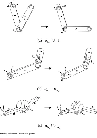
The construction procedure of the metamorphic kinematic joints can be illustrated in Fig. 2. Firstly, the joints should be listed according to the sequence indicated in the corre-sponding operation result. Further, geometric limit is used to realize the transformations between these adjacent joints in sequence. Geometric limit is a most common way of mak-ing the type of kinematic joints to be changed by releasmak-ing or adding appropriate constraints at suitable geometric loca-tions. Such as in Fig. 2a, the kinematic joint between linksa
andb is a revolute joint whose axis is parallel to the adja-cent revolute joint,R1. In the next configuration, the revolute
joint is locked. Therefore, two limiting stoppers are laid on the two linksa andb, respectively. When the two stoppers are contacted, the two links are fixed together and the num-ber of DOF of the revolute joint is changed to zero in Fig. 2a. Figure 2b shows that the joint is performing translating mo-tions with arrows denoting the direction of pin’s motion and indicating the number of DOFs the joint possesses. When the
pin reaches the position shown in the second figure, it stops translating but remains rotating as shown. This is identified as a typical metamorphic kinematic joint that varies from a prismatic joint to a rotating pair. Similarly, Fig. 2c demon-strates a series of varying orientations of a revolute pair un-dergoing the orientations about different axes, successively.
According to the construction process described above, the matrix of the original metamorphic mechanism for the five-bar metamorphic linkage shown in Fig. 1 is
A0=
e R∪ −1∪R 0 0 RkR∪ −1
{1,5} a RkR∪ −1∪RkR 0 0
0 {1,2,3} b RkR∪ −1∪RkR 0
0 0 {1,3,4} c −1∪P⊥R
{1,5} 0 0 {1,2} d
. (8)
Therefore, the original metamorphic mechanism can be gen-erated by applying the uniting operator to all of the mecha-nism’s configurations and using link and joint information. In particular, the matrix which includes the information of all links and their connectivity relationships can make us identify all possible combinations between links for creat-ing different mechanisms. So the mechanism is helpful to develop novel metamorphic mechanisms using the represen-tation method.
4.2 The joint variation matrix
The essential method for realizing configuration transforma-tion of metamorphic mechanisms is to change the charac-teristics of kinematic joints, which lead to variations in the topology of the entire mechanism. Therefore, to determine the joint variation rule for two adjacent configurations of a mechanism, a generalized difference operation for two adja-cency matrices is proposed.
Let A(varm+1,m) be the joint variation matrix, which can be
described as the result of applying the generalized difference operator to the topological representation matrices A(m+1) and A(m), that is
A(varm+1,m)=A(m+1)−A(m), (9) where – represents the generalized difference operator (Lan and Du, 2008; Li et al., 2010). The resulting matrix contains information about the joint variation when the mechanism is transformed from configurationmto configurationm+1. If the mechanism is transformed from configurationm+1 to configurationm, the joint variation matrix A(varm,m+1) can be
expressed as
y x
1
R
z
PR R
1
b
a
y
x z
1
R
a
b
-1
(a)
R
PR1U
-1
x y
z
a
b
PR P
1
1 R
y
x
z
a
b
1
R
PR
R
1
(b)
P
PRU
R
PR1 1
1
R
PR
R 1
x
y z
a
b
x
y z
1
R R⊥R1
a
b
(c)
R
PRU
R
⊥R1 1
Figure 2.The result of uniting different kinematic joints.
equal, the corresponding element in matrix A(varm+1,m)is
as-signed the number 0. Conversely, the elements in the minu-end matrix are reserved directly, and the principal diagonal elements remain unchanged for recognition purposes. The same rule is used for the lower off-diagonal elements. If an upper off-diagonal element is unchanged, the corresponding lower off-diagonal element needs to be assigned the value 0 regardless of its actual value. The joint variation matrix can be constructed directly from the physical meaning of the joint variation rule. In addition, analysing the existing joints with the characteristic of metamorphosis is one of the most impor-tant approaches for achieving the principle of constructing the corresponding joint variation matrix.
Therefore, joint variation matrices for configurations 1 to 5 are given as follows:
A(2var,1)=
e 0 0 0 0
0 a −1 0 0
0 2 b 0 0
0 0 0 c P⊥R
0 0 0 2 d
,
A(3var,2)=
e 0 0 0 0
0 a RkR 0 0
0 3 b −1 0
0 0 3 c 0
0 0 0 0 d
,
A(4var,3)=
e −1 0 0 0
4 a 0 0 0
0 0 b RkR 0
0 0 4 c 0
0 0 0 0 d
,
W. Zhang et al.: A representation of the configurations and evolution of metamorphic mechanisms 45
A(5var,4)=
e R 0 0 −1
5 a 0 0 0
0 0 b 0 0
0 0 0 c 0
5 0 0 0 d
. (11)
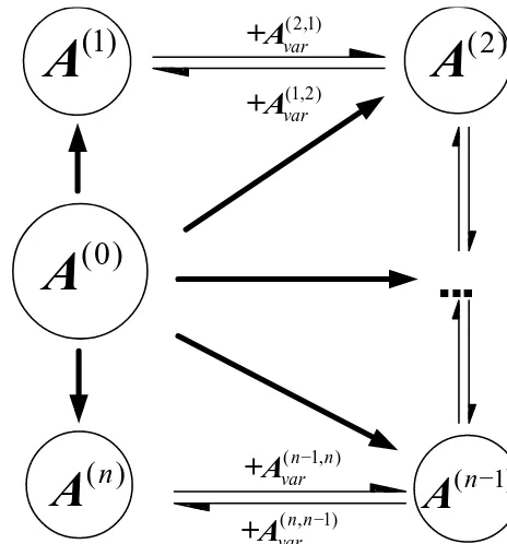
4.3 The relationship between the original metamorphic mechanism and the mechanism in any configuration Because an original metamorphic mechanism provides a foundation for a mechanism to transform itself into any con-figuration and expresses the joint variation characteristics from the symbolic adjacency matrices and the correspond-ing operations, the relationships between these matrices is as shown in Fig. 3.
1. The relationship between adjacent configurations: the two adjacent matrices shown in Fig. 3 can be trans-formed into each other using a joint variation matrix. From Eq. (9), the matrix A(m+1)can be expressed as A(m+1)=A(m)+A(varm+1,m), (12) where +represents the generalized addition operator, which changes the elements in matrix A(m)according to the corresponding elements in the joint variation matrix of A(varm+1,m). Comparing the corresponding elements in
the two matrices, the lower off-diagonal elements in A(varm+1,m)containing the valuemare selected, with the
corresponding symmetrical upper triangular elements, to replace the corresponding elements in matrix A(m) while leaving the other elements unchanged. Similarly, matrix A(m)can be expressed as
A(m)=A(m+1)+A(varm,m+1). (13) For example, the relationship between matricesA(1)and
A(2)is
A(2)=A(1)+A(2var,1) (14)
A(1)=A(2)+A(1var,2). (15)
2. The relationships of the original metamorphic mecha-nism and the mechamecha-nism in a single configuration: the original metamorphic mechanism is able to evolve into any configuration. Therefore, the information on the mechanism in configurationmcan be extracted from the matrix A(0)to construct the corresponding matrix A(m). The process of evolution from A(0)to A(m)follows from Eq. (3).
First, the principal diagonal elements denoting the links in A(0) are placed in their corresponding positions in A(m) di-rectly. Then, the lower off-diagonal elements containing the value 1 and their corresponding upper off-diagonal elements, which represent constraints on the joints of links in matrix
(1)
A
A
(2)
(
n
−
1)
A
( )
n
A
(0)
A
(1,2) var
+A
( 2,1) var+A
( ,n n 1) var
−
+A
(n 1, )n var−
+A
Fig. 3 The relationship between the original metamorphic mechanism and the mechanism in
any configuration
Figure 3. The relationship between the original metamorphic mechanism and the mechanism in any configuration.
A(0), are similarly mapped to positions in A(m)as long as the value of the corresponding element is notm. The next impor-tant step is to select a numbermfrom the elements compris-ing sets of numbers and then, to identify its sequence number in the set{a(1)j,i, . . . ,aj,i(m), . . . ,a(j,in)}. The sequence number can be used to determine the corresponding joint constraint
con-veniently using the element
n−1 Q
m=1
Ji,j(m)∪Ji,j(m+1). These ele-ments are then placed into A(m), the other elements of which
are assigned a value of 0.
For example, the elements marked by black trianglesHin Eq. (16) are extracted to construct the matrix A(2) , which represents the topology of the mechanism in configuration 2 according to the above procedure.
A0=
e
H RH∪ −1∪R 0 0 RkHR
∪ −1
{1
H,5} aH RkR∪ −H1∪RkR 0 0
0 {1,2
H,3} bH RkHR
∪ −1∪RkR 0 0 0 {1
H,3,4} cH −1∪P⊥HR
{1
H,5} 0 0 {1,2H} dH
(16)
The diagram in Fig. 3 shows that the evolutionary relation-ships between the original metamorphic mechanism and all of its configurations can be determined by applying matrix operations to the appropriate matrices.
5 Case study
A
B
C
D
a
b
c
d
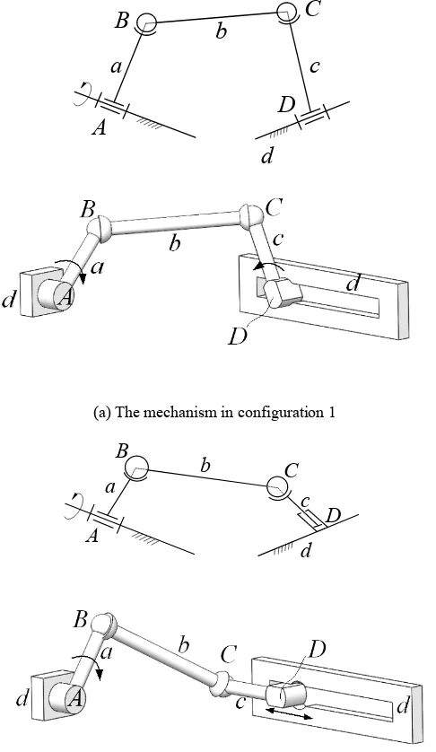
(a) The mechanism in configuration 1
A
B
C
D
a
b
c
d
(b) The mechanism in configuration 2
Figure 4.A four-bar spatial metamorphic mechanism.
RSSR mechanism. The axis of jointDbetween linkscandd
is perpendicular to the axis of jointAbetween linksaandd. When revolute jointDis transformed into a prismatic joint, the mechanism becomes an RSSP mechanism, as shown in Fig. 4b.
The topological structures of the metamorphic mechanism can be expressed in matrix form as follows:
A(1)=
d R 0 R⊥R
1 a S 0
0 1 b S
1 0 1 c
(17)
A(2)=
d R 0 PkR
1 a S 0
0 1 b S
2 0 1 c
. (18)
The origin matrix of the original metamorphic mechanism and the joint variation matrix can be expressed as
A(2var,1)=A(2)−A(1)=
d 0 0 R⊥R
0 a 0 0
0 0 b 0
2 0 0 c
(19)
A(0)=A(1)∪A(2)=
d R 0 R⊥R∪PkR
1 a S 0
0 1 b S
{1,2} 0 1 c
. (20)
The elementR⊥R∪PkRin matrix A(0)represents the way
in which both the axial orientation and the type of jointD
have changed. There, the joint can be considered a meta-morphic kinematic joint and be developed according to the variation sequence for the kinematic behaviours of the entire mechanism.
6 Conclusions
The paper proposed a comprehensive symbolic matrix for characterizing the topology of a metamorphic mechanism that involved information on the variations of links and the axial orientations of the kinematic joints. In addition, oper-ations on the matrices of the adjacent configuration mech-anisms are defined to construct an origin matrix and joint variation matrices. In particular, the construction and evolu-tion of the matrix representaevolu-tion for an original metamorphic mechanism show how it can be transformed into any config-uration matrix. The relationship between the original meta-morphic mechanism and all of its possible configurations and methods of moving between them were presented. Examples illustrate the effectiveness of this approach in characterizing metamorphic mechanisms. The configuration representation of metamorphic mechanisms provides a foundation for the analysis and synthesis of novel metamorphic mechanisms.
Acknowledgements. The authors gratefully acknowledge the support of the National Natural Science Foundation of China (Project No. 51575018, No. 51275015 and No. 51175494) and the Foundation of State Key Laboratory of Robotics (No. 2014).
Edited by: J. Schmiedeler
Reviewed by: two anonymous referees
References
Dai, J. S. and Rees Jones, J.: Mobility in metamorphic mechanisms of foldable/erectable kind, in: Proceedings of the 25th ASME Bi-ennial Mechanisms and Robotics Conference, Baltimore, 1998. Dai, J. S. and Rees Jones, J.: Matrix representation of topological
changes in metamorphic mechanisms, ASME Trans. J. Mech. Design, 127, 610–619, 2005.
Dai, J. S., Ding, X. L., and Zou, H. J.: Fundamentals and catego-rization of metamorphic mechanisms, Chinese J. Mech. Eng., 41, 7–12, 2005a.
Dai, J. S., Ding, X. L., and Wang, D. L.: Topological changes and the corresponding matrix operations of a spatial metamorphic mechanism, Chinese J. Mech. Eng., 41, 30–35, 2005b.
Herve, J. M.: Translational parallel manipulators with douple planar limbs, Mech. Mach. Theory, 41, 433–455, 2006.
Korves, B. A., Slaboch, B. J., and Voglewede, P. A.: Mechanism state matrices for spatial reconfigurable mechanisms, in: Pro-ceedings of the ASME 2012 International Design Engineering Technical Conferences & Computers and Information in Engi-neering Conference, Chicago, 2012.
Lan, Z. H. and Du, R.: Representation of Topological Changes in Metamorphic Mechanisms with Matrices of the Same Dimen-sion, ASME Trans. J. Mech. Design, 130, 074501-1–074501-4, 2008.
Li, D. L., Zhang, Z. H., and McCarthy, J. M.: A constraint graph representation of metamorphic linkages, Mech. Mach. Theory, 4, 228–238, 2010.
Li, S. J. and Dai, J. S.: Configuration transformation matrix of meta-morphic mechanisms and joint-orientation change metameta-morphic method, China Mech. Eng., 21, 1698–1703, 2010a.
Li, S. J. and Dai, J. S.: Structure of Metamorphic Mechanisms Based on Augmented Assur Groups, China Mech. Eng., 46, 22– 41, 2010b.
Li, S. J., Wang, D. L., and Dai, J. S.: Topology of kinematic chains with loops and orientation of joints axes, Chinese J. Mech. Eng., 45, 34–40, 2009.
Liu, C. H. and Yang, T. L.: Essence and characteristics of metamor-phic mechanism and their metamormetamor-phic ways, in: Proceedings of the 11th World Congress in Mechanism and Machine Science, Tianjin, 2004.
Slaboch, B. and Voglewede, P.: Mechanism state matrices for planar reconfigurable mechanisms, ASME Trans. J. Mech. Robot., 3, 011012-1–011012-7, 2011.
Tsai, L.-W.: Mechanism Design: Enumeration of kinematic struc-tures according to function. CRC Press LLC, Boca Raton, FL, 2001.
Wang, D. L. and Dai, J. S.: Theoretical foundation of metamorphic mechanism and its synthesis, Chinese J. Mech. Eng., 43, 32–42, 2007.
Yan, H. S. and Kuo, C. H.: Topological representations and char-acteristics of variable kinematics joints, ASME Trans. J. Mech. Design, 128, 384–391, 2006.
Yan, H. S. and Kang, C.-H.: Configuration synthesis of mecha-nisms with variable topologies, Mech. Mach. Theory, 44, 896– 911, 2009.
Yang, T. L.: Topology structure design of robot mechanisms, China Machine Press, 2004.
Zhang, L. P., Wang, D. L., and Dai, J. S.: Biological modeling and evolution based synthesis of metamorphic mechanisms, ASME Trans. J. Mech. Design, 30, 1–11, 2008.
Zhang, W. X. and Ding, X. L.: A method for configuration repre-sentation of metamorphic mechanism with information of com-ponent variation, in: Advances in Reconfigurable Mechanisms and Robots I, edited by: Dai, J. S., Zoppi, M., and Kong, X., Springer, London, 2012.