R E S E A R C H
Open Access
Biomechanical testing of distal femur osteotomy
plate fixation techniques: the role of simulated
physiological loading
Justus-Martijn Brinkman
1*, Christof Hurschler
2, Jens Agneskirchner
3, Philip Lobenhoffer
3, René M Castelein
4and Ronald J van Heerwaarden
1Abstract
Background:Implants for fracture and/or osteotomy fixation are often tested according to basic mechanical test models such as open gap tests or 4-point-bending tests. These may be suitable to test and compare different implants for safety and clinical approval, but are not always representative of the post-operative situation, which is decisive when it comes to bone healing. In the current study the Knee Expert Group of the Association for the Study of Internal Fixation has compared the available open gap test results of the latest version of the TomoFix Medial Distal Femoral Plate and the antecedent plate design, with the test results of a more physiological and life-like test model. In the open gap test model the antecedent plate design was found to have superior stiffness and fatigue strength.
Methods:In the current study simulated postoperative conditions for medial closing wedge supracondylar osteotomies were used. The constructs were subjected to cyclical axial and torsional loading and were subsequently tested to failure. Results:The more life-like tests in this study showed that the latest version was either more or equally stable and stiff than the antecedent version of the plate, in all of the tests. It is argued that the difference in results between the two loading models is due to differences in test design.
Conclusions:These test results stress the importance of not only using standard open gap and 4-point-bending tests, but also to use as life-like as possible test conditions for any form of biomechanical testing of new implants.
Keywords:Plate fixation; Biomechanical testing; Femur osteotomy; Fracture; Stability
Background
Implants for fixation of fractures and osteotomies have since long been tested for safety and clinical approval and have been compared to each other in so called open gap or 4-point-bending biomechanical test models [1–6]. The biomechanical loading protocols used aim at testing construct stability and fixation strength to bone and in-clude in general axial and torsion loading, stiffness and fatigue testing. Although the open gap model purposely represents a worst case scenario of implant loading in un-stable fractures, for many fractures and closing wedge oste-otomies however this model represents a non-physiological test situation. The reduced fracture fragments or closed
osteotomy gap are likely to improve the overall stability and stiffness of the construct [7–9].
In recent years so called Locking Compression Plates (LCP) have been developed specifically for fixation of osteotomies around the knee. Various factors have been identified to influence construct stability of LCP in plate fixation techniques; working length (i.e. distance of the first screw to the fracture), number of screws, distance of the plate to the bone, gap size and plate length [2]. In-creased working length, fewer screws, a greater distance of the plate to the bone, an increased gap size and a shorter plate all negatively influenced the stability of the construct [2]. These parameters have been investigated using com-posite cylinders and finite element analysis (FEA) under simulated non-physiological loading conditions [2].
The latest version of the TomoFix Medial Distal Femoral Plate (MDF) (Synthes GmbH, Switzerland), has shown * Correspondence:[email protected]
1
Department of Orthopaedics, Limb deformity reconstruction unit, Sint Maartensclinic, Woerden, The Netherlands
Full list of author information is available at the end of the article
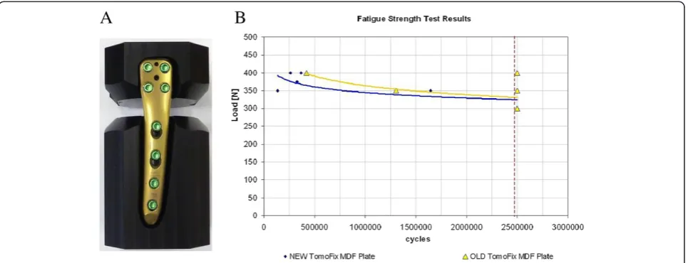
equal static strength but inferior stiffness and fatigue strength when compared to the antecedent plate design under these non-physiological testing conditions (Figure 1A and B), performed in house by the plates manufacturer.
These results were evaluated by a group of osteotomy experts involved in the development of plates for fix-ation of osteotomies around the knee; the Knee Expert Group (KNEG) of the Association for the Study of Internal Fixation (AO/ASIF). They questioned the val-idity and the clinical relevance of the open gap model in the testing of closing wedge osteotomy techniques. It was argued that open gap and 4-point-bending tests, while being necessary from a safety standpoint, test the material and design properties of the implant, but are not a repre-sentation of the stability of the whole construct, once it is implanted in the patient.
A validated biomechanical testing model with life-like simulated loading conditions has been previously used to compare the construct stability of different types of plate fixation techniques for distal femur osteotomies, one of which was the antecedent version of the MDF plate [7,8]. The new design MDF plate has a different shape than its predecessor; it has a more anatomical pre-formed shape resulting in an improved fit to the dis-tal femur which reduces the distance of the plate to the bone, subsequently reducing leverage forces resulting on the plate (Figure 2). It has an optimized screw-hole orientation, providing a better fit for the screws in the femur. It has also been made slightly shorter and slim-mer in favor of reduced prominence, while the thickness of both plates is the same.
In this study both designs were tested under axial and torsion loads in a material testing machine (MTS) in a composite replicate femur model, under simulated physio-logical loading conditions. The composite bone model provided reproducible bone properties and avoided the availability problems and variability associated with ca-daver specimens. The mechanical properties of these bones have been validated [10]. The study hypothesis was that, in contrast to the open gap model test results, there is no difference in stability and stiffness between the two designs using a simulated physiologic post-operative test model for comparison.
Methods
The same test protocol as has been previously used by Brinkman et al. was used in the current study [7,8]. Fourteen femurs in total were available; 7 for each plate type (‘NEW’, anatomical MDF plate and‘OLD’, antecedent MDF plate, Table 1). Bi-plane closing wedge distal femur osteotomies were performed, and the plates implanted according to standard surgical technique [11]. All femurs were aligned in a standardized way using an alignment jig and a femur saw guide (Balansys, Mathys Medical, Bettlach, Swiss), the closing wedge osteotomy was di-rected 20° oblique to the distal femur condylar line, a wedge of 10° was removed. The bone deformation needed for the closing of the wedge and the implant fixation were performed without producing a fracture in the op-posite bone bridge. The femur head and trochanter and the distal femur end were thereafter embedded in a polyurethane-based cold-curing resin (Ureol FC 53,
Figure 1Open gap test setup and results. A.Anatomical MDF plate fixated in composite cylinder blocks for open gap model testing.B.
Vantico GmbH, Wehr, Germany) in a specially con-structed fixture; the fixture allowed for mounting of the femur in a materials testing machine (MTS) (Mini Bionix, MTS Systems Corporation, Eden Prairie, MN, USA) (Figure 3). The fixture was designed in such a way that the axis of loading of the replicate femur in the MTS was through the centre of the femur head proximal and through a point 18-mm medial from the mid-condylar distance, creating a mechanical femur axis of 2°; repro-ducing loading in the normally aligned human knee after a supra-condylar femur osteotomy (SCO) for valgus osteoarthritis.
Measuring system
The principles of rigid body motion were used to meas-ure (micro) motion across the SCO. Reference point pairs, relative to which motion was measured, were de-fined on the replicate femur both proximal and distal to the osteotomy gap; two points across the midpoint of the intact cortical bone bridge, two points midway across the osteotomy and two points just posterior of the plate on the femur. Motion (displacement) of the diaphysis of the femur proximal to the osteotomy was measured relative to the femur condyles distal to the osteotomy using an ultrasound 3D motion-analysis system (CMS20S, Zebris Medizintechnik, GmbH, Isny, Germany). This system is based on the travel time measurement of ultra-sonic pulses that are emitted by miniature speakers on a marker-triplet to microphones on a second marker-quartet (Figure 2). It has been previously used by Brinkman et al. in biomechanical testing of various osteotomy tech-niques [7,8].
Loading protocol
The replicate femurs were subjected to axial and torsional loading protocols designed to simulate physiological load-ing (Table 1). Cyclical axial loadload-ing was performed at two loading levels (150 and 800 N) on all femurs, during 100 cycles for each load at a rate of 0.5 Hz. Cyclical tor-sional loading was thereafter performed in all femurs. In-ternal rotation around the Z-axis with a cyclical moment loading of 5 Nm at a rate of 0.25 Hz was applied during 100 cycles, with an increasing axial pre-load (Table 1). The different axial preloads were used to simulate no, par-tial and full weight bearing.
Four femurs were subsequently tested to failure under axial compression, with displacement control at a rate of 0.1 mm per second. Failure was defined by a drop of ac-tuator loading, either because of failure of the bone, bone–implant construct, or of the implant itself. Three femurs were tested to failure under torsion, with dis-placement control at a rate of 0.25° per second. Criteria for failure were the same as used for the axial loading failure tests.
Data analysis
The displacement data recorded was computed using a custom-written program in Mathematica (version 5.0, Wolfram research, Inc, Champaign, IL, USA); the change in position and the angle of rotation around all axes for each measuring point and the change in absolute distance between the measuring points was calculated. Displace-ment at the SCO was calculated using the change in the (absolute) distance between the measuring points per loading cycle. The amount of motion that occurs at the
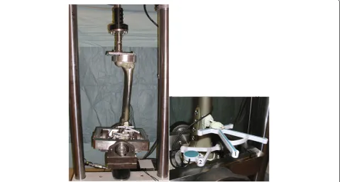
Table 1 Overview of the configurations and test protocols
Implant type Axial loading Torsional loading
Axial loads 5NM torsion load
With axial pre load
Total no Test runs 1 2 3 4 5
Femurs 150 N 800 N 0 N 150 N 800 N
7 MDF OLD 100 100 100 100 100
7 MDF NEW 100 100 100 100 100
14
Overview of the test runs: axial tests at 150 N and 800 N both 100 cycles per test run, torsion tests at 5 Nm, with 0 N, 150 N and 800 N axial pre-load, again 100 cycles per test run.‘MDF NEW’= anatomical MDF plate,‘MDF OLD’= antecedent MDF plate.
SCO was defined as the difference between the max-imum increase and maxmax-imum decrease in the distance between measuring points; determined for each cycle and per measuring point. A greater mean difference cal-culated over 100 cycles and 3 measuring points indicates more motion allowed by the bone–implant construct. Sta-bility was subsequently defined as the amount of motion allowed by the construct. A similar approach was used in the torsional tests. The amount of motion was calculated by determining the amount of rotation around the Z-axis that is allowed by the bone–implant construct during each cycle. Stability in torsion was defined as the amount of ro-tation allowed by the construct. The stiffness under axial compression of the construct was calculated by plotting displacement at the SCO during the failure test, defined as the average amount of movement on the Z-axis of the 3 previously defined point pairs, against the force data. Stiff-ness of the bone–implant construct was defined as the slope of the linear portion of the force - deformation curve (i.e. the force required per millimeter of displacement). Stiffness under torsion loading was calculated by plotting the rotation around the Z-axis over time against the moment (Nm) applied by the MTS and defined as Nm re-quired for one degree of rotation.
Statistical analysis
Statistical analysis was performed using SPSS statistical software (Version 11.5, SPSS, Inc, Chicago, IL, USA); the independent sample T-test was used to measure statistical
differences between the motion data that was recorded and subsequently computed for the two configurations, P values < 0.05 were considered significant using a 95% confidence interval (CI95).
Results
Axial tests
No visible damage to bone, bone-implant construct or implant was found in any of the test runs. During each cycle of loading and unloading, a corresponding move-ment at the osteotomy was observed to occur. At 800 N the anatomical MDF plate allowed statistically signifi-cantly less motion than the antecedent MDF plate, at 150 N there was no difference (Table 2).
Torsion tests
Again no visible damage to bone, bone-implant con-struct or implant was found in any of the test runs. In the test run with no axial preload the anatomical MDF plate allowed statistically significantly less motion than the antecedent MDF plate; in the other runs there was no difference between the two (Table 2).
Axial failure tests
Seven failure tests (4 antecedent MDF plate, 3 anatomical MDF plate) resulted in a per-trochanteric femoral neck failure, i.e., failure occurred proximally to the osteotomy in the replicate femurs. In one femur with the anatomical MDF plate a two level femur fracture occurred; a femoral
neck fracture as in the other tests, but a femur shaft frac-ture just proximal to the plate occurred as well. No macro-scopically observable failure at the bone-implant interface or of the implant itself was observed in any of the tests. No fractures of the opposing lateral cortex bone-bridge were observed with both plates. During the axial failure tests, the force time course of loading typically demonstrated in-creasing motion with inin-creasing axial compression load with a sudden drop in load at failure. Calculated stiffness was similar in both plate types (Table 3).
Torsion failure tests
In the 6 femurs that were tested to failure under torsion loads, different patterns of failure were observed. Two fe-murs (one anatomical MDF plate, one antecedent MDF plate) did not fail, the test ended because the drive-shaft of the MTS itself came loose, which became apparent by a sudden drop in load on the femur. In those two there was no visible damage to the construct, their calculated stiff-ness did not differ from the other femurs. In two (again one anatomical MDF plate, one antecedent MDF plate) the test ended because of a fracture at the biplane hinge
on the lateral cortex bone-bridge. And in two (one ana-tomical MDF plate, one antecedent MDF plate) a spiral fracture occurred just proximal of the osteotomy, just an-terior of the proximal screw-bone interface. Calculated stiffness again was similar in both plates (Table 3).
Discussion
The most important finding in this study was that in contrast to the results of the open gap tests, the anatom-ical MDF plate was not found to be statistanatom-ically signifi-cantly less stable and stiff than the antecedent MDF plate. In two test runs the anatomical MDF plate allowed statistically significantly less motion than the antecedent MDF plate (800 N axial test and the torsion test with no axial pre-load). In all the other tests there was no statis-tically significant difference between the two. Again as in previous studies the axial failure tests ended because of per-trochanteric femoral neck fractures, not because of failure at the osteotomy7. Stiffness in the current tests also was very similar in both plates, with the antecedent MDF plate on average showing a slightly higher stiffness, but not statistically significant. In the torsion failure tests, the failure modes differed somewhat between femurs, but again there was no difference between the two plates. Again the antecedent MDF plate showed a slightly higher stiffness on average, but not statistically significant.
In these tests, as in previous tests by Brinkman et al., the post-operative situation after medial closing wedge SCO was reproduced as“life-like” as possible, with sim-ulated partial and full weight bearing and simsim-ulated leg alignment as in patients that undergo SCO [7,8].
In the open gap model which is often used to compare the mechanical strength of osteosynthesis implants, a composite cylinder is cut in half and both ends are fix-ated with a plate (Figure 1A). That construct is then tested under axial and torsion loads, with motion mea-sured across the gap. As documented by Stoffel et al. gap size and plate length are important factors in the overall stability [2]. It is therefore not unexpected that under these circumstances a shorter and slimmer plate has a lower stiffness and fatigue strength than a plate that is longer and that has an expanded shaft.
Various authors have compared different types of plates and nails, and different types of screw configurations, using sawbones or human cadaver bones, in distal femur and proximal tibia fracture models [1,3–6,9]. Almost all use some form of gap model; with the gap representing the unstable fracture [1,3–6]. David et al. used anatomic reduction without fracture gaps in a cadaver study testing a locked nail and an angled blade plate [9]. They stated that direct bony opposition more closely approximates the clinical situation, in which fracture fragments are reduced anatomically before placement of the fixation device. So as a consequence of the fracture reduction in most fractures
Table 2 Axial and torsion test results
Total runs Mean SD
Axial tests 150 N NEW plate 700 0.085651 0.054997
OLD plate 700 0.087737 0.056193
800 N NEW plate 700 0.088803 0.048292
OLD plate 700 0.096411 0.044069*
Torsion tests 0 N NEW plate 700 0.077263 0.022999
OLD plate 700 0.080334 0.025255*
150 N NEW plate 700 0.076817 0.02146
OLD plate 700 0.078167 0.023
800 N NEW Plate 700 0.076932 0.021548
OLD plate 700 0.077137 0.02275
*Statistically significantly less motion with the anatomical MDF plate design. Results for the axial and torsion test runs, movement is in mm for the axial tests and in degrees for the torsion tests.‘NEW plate’= anatomical MDF plate,
‘OLD plate’= antecedent MDF plate.
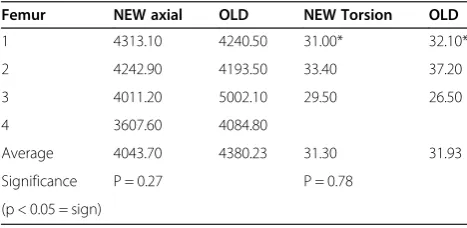
Table 3 Axial and torsion failure test results
Femur NEW axial OLD NEW Torsion OLD
1 4313.10 4240.50 31.00* 32.10*
2 4242.90 4193.50 33.40 37.20
3 4011.20 5002.10 29.50 26.50
4 3607.60 4084.80
Average 4043.70 4380.23 31.30 31.93
Significance P = 0.27 P = 0.78
(p < 0.05 = sign)
Results for the axial and torsion failure tests, axial force is in N/mm, torsion force is Nm/°; differences are not statistically significant.
*Femurs in which the drive-shaft of the MTS came loose.
stability is likely to be increased, which is not simulated in gap models. Similarly in closing wedge SCO there is no gap, both ends of the osteotomy are rigidly compressed against each other. And because of the controlled nature in which the SCO is created, closed and fixated there is in-herent stability of the construct. Furthermore because of the gap in gap model testing the loading conditions at the plate are completely different, in a gap model the plate is loaded under tension, in the current setup under com-pression, because it is on the medial side of the femur. In SCO the load at the knee is shifted from lateral to medial, therefore after SCO the compressive forces will be on the medial side, as is the case in the current test setup.
The above arguments can also be made against con-cerns over the inferior results of the anatomical MDF plate in the fatigue tests using an open gap test model; they were not performed under simulated post-operative conditions. Fatigue testing with an open gap model may give a better understanding of the plate’s failure mode. However it is questionable whether fatigue test results are representative of the clinical situation in SCO, be-cause ongoing bone-healing will stabilize the construct as the implant fatigues, i.e., load sharing takes place de-creasing the loading on the plate. Closing wedge SCO typically heal in 6–12 weeks, specific postoperative re-habilitation protocols provide for partial and full weight-bearing tailored to stability of fixation construct and time to full bone healing [12]. In our experience bone healing using a bi-plane osteotomy technique is fast and increased stability through bone healing occurs quickly [11]. This whole process is not simulated in any biomech-anical test setup and can only be documented in in-vivo bone healing studies.
Limitations of the study are that, because of the small number of femurs available, the failure data set is small in size. No fatigue tests were performed, due to data size collection and time limitations. The MTS is not able to reliably load the construct quickly therefore fatigue test-ing of a stest-ingle femur would have taken weeks. No power calculations were performed and no test- re-test reliabil-ity measurements were performed.
As with all experimental tests, the test setup used does not account for the variation in host biology and is a rep-resentation of what could happen in vivo and is for sure a simplification. The forces that are exerted on a leg during flexion and extension were not simulated; simple axial and torsional loading was used. These limitations are true however for most if not all types of biomechanical testing models. Furthermore the data is not comparable to the two previously published biomechanical studies by Brink-man et al., because 4thgeneration sawbones were used in-stead of 3rdas the 3rdgeneration sawbones are no longer commercially available [7,8]. According to Heiner the 4th generation bones mirror human bones more closely than
the 3rd [10]. Tests with the 4th generation bones should therefore, if anything, be more representative of the post-operative situation after SCO.
Conclusions
The current test results show that under simulated physiological loading conditions there is no difference in stability between the two plates; the latest design Tomofix MDF provides as much, if not more, stability and equal stiffness compared to the antecedent design. These test results stress the importance of not only using standard open gap and 4-point-bending tests, but also to use as life-like as possible test conditions for any form of biomechanical testing of new implants.
Competing interests
A grant was provided by Synthes GmbH and received by the Medizinischen Hochschule Hannover, Germany, to perform the current study. They had no influence whatsoever on its outcome and the data published in this study.
Authors' contributions
JMB performed the tests, computed the results and drafted the manuscript. CH wrote the custom software and was one of the primary developers of the measuring method, he supervised the laboratory work. CH, JA and PL conceptualized the original as-life-like as possible test setup for testing of osteotomies, they supervised the project and helped draft the manuscript. RMC helped draft the manuscript. RJvH was the main supervisor of the project and was one of the KNEG members that came up with the idea of challenging the open gap tests. All authors read and approved the final manuscript.
Acknowledgments
We would like to thank Hans Radenborg for his help with performing the osteotomies.
J.M. Brinkman would like to thank the Marti- Keuning Eckhardt Foundation for their support of his scientific work.
Author details
1
Department of Orthopaedics, Limb deformity reconstruction unit, Sint Maartensclinic, Woerden, The Netherlands.2Labor für Biomechanik und Biomaterialien, Orthopädische Klinik der Medizinischen Hochschule Hanover, Hanover, Germany.3Sportsclinic Germany, Hanover, Germany.4Department of Orthopedics, University Medical Centre Utrecht, Utrecht, The Netherlands.
Received: 12 December 2013 Accepted: 10 April 2014 Published: 26 June 2014
References
1. Ito K, Grass R, Zwipp H (1998) Internal fixation of supracondylar femoral fractures: comparative biomechanical performance of the 95-degree blade plate and two retrograde nails. J Orthop Trauma 12:259–266
2. Stoffel K, Dieter U, Stachowiak G, Gachter A, Kuster MS (2003) Biomechanical testing of the LCP–how can stability in locked internal fixators be controlled? Injury 34(Suppl 2):11–19
3. Zlowodzki M, Williamson S, Cole PA, Zardiackas LD, Kregor PJ (2004) Biomechanical evaluation of the less invasive stabilization system, angled blade plate, and retrograde intramedullary nail for the internal fixation of distal femur fractures. J Orthop Trauma 18:494–502
4. Crist BD, Khalafi A, Hazelwood SJ, Lee MA (2009) A biomechanical comparison of locked plate fixation with percutaneous insertion capability versus the angled blade plate in a subtrochanteric fracture gap model. J Orthop Trauma 23:622–627
6. Heiney JP, Barnett MD, Vrabec GA, Schoenfeld AJ, Baji A, Njus GO (2009) Distal femoral fixation: a biomechanical comparison of trigen retrograde intramedullary (i.m.) nail, dynamic condylar screw (DCS), and locking compression plate (LCP) condylar plate. J Trauma 66:443–449
7. Brinkman JM, Hurschler C, Agneskirchner JD, Freiling D, van Heerwaarden RJ (2011) Axial and torsional stability of supracondylar femur osteotomies: biomechanical comparison of the stability of five different plate and osteotomy configurations. Knee Surg Sports Traumatol Arthrosc 19:579–587 8. Brinkman JM, Hurschler C, Staubli AE, van Heerwaarden RJ (2011) Axial and torsional stability of an improved single-plane and a new bi-plane osteotomy technique for supracondylar femur osteotomies. Knee Surg Sports Traumatol Arthrosc 19:1090–1098
9. David SM, Harrow ME, Peindl RD, Frick SL, Kellam JF (1997) Comparative biomechanical analysis of supracondylar femur fracture fixation: locked intramedullary nail versus 95-degree angled plate. J Orthop Trauma 11:344–350
10. Heiner AD (2008) Structural properties of fourth-generation composite femurs and tibias. J Biomech 41:3282–3284
11. Freiling D, van Heerwaarden R, Staubli A, Lobenhoffer P (2010) The medial closed-wedge osteotomy of the distal femur for the treatment of unicompartmental lateral osteoarthritis of the knee. Oper Orthop Traumatol 22:317–334
12. Freiling D, Lobenhoffer P, Staubli A, van Heerwaarden RJ (2008) Medial closed-wedge varus osteotomy of the distal femur. Arthroskopie 21:6–14
doi:10.1186/s40634-014-0001-1
Cite this article as:Brinkmanet al.:Biomechanical testing of distal femur osteotomy plate fixation techniques: the role of simulated physiological loading.Journal of Experimental Orthopaedics20141:1.
Submit your manuscript to a
journal and benefi t from:
7 Convenient online submission
7 Rigorous peer review
7 Immediate publication on acceptance
7 Open access: articles freely available online
7 High visibility within the fi eld
7 Retaining the copyright to your article