https://doi.org/10.5194/ms-9-51-2018
© Author(s) 2018. This work is distributed under the Creative Commons Attribution 4.0 License.
Design and evaluation of a continuum robot with
extendable balloons
Efe Yamac Yarbasi1and Evren Samur2
1School of Aerospace Engineering, Georgia Institute of Technology, Atlanta, GA 30308, USA
2Department of Mechanical Engineering, Bogazici University, Istanbul, 34342, Turkey
Correspondence:Evren Samur ([email protected])
Received: 12 July 2017 – Revised: 9 November 2017 – Accepted: 28 December 2017 – Published: 7 February 2018
Abstract. This article presents the design and preliminary evaluation of a novel continuum robot actuated by two extendable balloons. Extendable balloons are utilized as the actuation mechanism of the robot, and they are attached to the tip from their slack sections. These balloons can extend very much in length without having a sig-nificant change in diameter. Employing two balloons in an axially extendable, radially rigid flexible shaft, radial strain becomes constricted, allowing high elongation. As inflated, the balloons apply a force on the wall of the tip, pushing it forward. This force enables the robot to move forward. The air is supplied to the balloons by an air compressor and its flow rate to each balloon can be independently controlled. Changing the air volumes differ-ently in each balloon, when they are radially constricted, orients the robot, allowing navigation. Elongation and force generation capabilities and pressure data are measured for different balloons during inflation and deflation. Afterward, the robot is subjected to open field and maze-like environment navigation tests. The contribution of this study is the introduction of a novel actuation mechanism for soft robots to have extreme elongation (2000 %) in order to be navigated in substantially long and narrow environments.
1 Introduction
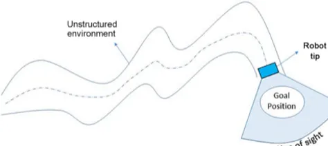
In order to achieve a high level of precision, rigidity has long been an optimization criterion for robot designers (Grossard et al., 2013). This resulted in very stiff robots that consist of rigid links. Although rigid-link robots dominate the industry, they cannot be of any help for some cases of diagnostic, pipe inspection, or medical applications, where a videoscope is used to access remote locations through narrow holes for vi-sualization. In such operations, flexibility of the manipulators would help greatly to reach difficult-to-access sites and com-plete the task with high dexterity (Rus and Tolley, 2015). The idea of designing and developing a robot that can be easily guided through unstructured, substantially-long and narrow environments to perform exploratory operations such as for natural disaster relief, or pipe inspection (Majidi, 2014) was the motivation that led to this research (see Fig. 1).
In order to achieve high maneuverability, a soft continuum-type design (Robinson and Davies, 1999) is uti-lized for the target application. In such applications, soft robots are safe to work with, since they are made of
obsta-serving a screening procedure.
cles. These advantages make this class of robots well-suited for highly dexterous tasks and tasks that include environmen-tal uncertainty (Katzschmann et al., 2015). With utilization of newly developed compliant matters and fabrication tech-niques and utilizing these matters in continuum robots, they can be enabled to tolerate very high strains and extreme con-figurations (Laschi et al., 2016). Backbones can be axially extended by utilizing different mechanisms, for example by actuating antagonistic tendons that are placed about the lon-gitudinal axis (Chirikjian and Burdick, 1994) with the option of spring loading (Tonapi et al., 2015) or having telescopic precurved concentric tubes along the backbone and rotating them independently (Swaney et al., 2015). A locally actuated backbone continuum robot design is the closest to the biolog-ical continuum structures (Walker, 2013). Backbone of these robots is directly formed by the actuators. This type of robots may also consist of modules, and each module can be actu-ated independently in order to enable the backbone to get into the desired configuration. A surgical instrument that consists of five successive flexible segments utilizes McKibben actu-ators (Chou and Hannaford, 1996) has been presented in the literature (Moers et al., 2012). This manipulator uses pneu-matic actuators in a parallel combination in each of its seg-ments and controls the position of the end effector by in-dependently controlling McKibben actuators. High precision can be achieved because of the stiffness of the manipulator and high pressures in the actuators. A similar design utilizing three fiber reinforced elastomeric enclosures in parallel com-bination has also been presented (Bishop-Moser et al., 2012). Another soft manipulator has been designed, and its defor-mation characteristics are analyzed in detail while perform-ing tasks (Marchese et al., 2015). As one might expect, an octopus arm has been a great example of a soft, continuum-type manipulator from nature. It has been studied in detail and a manipulator that mimics an octopus arm has been de-signed (Calisti et al., 2011; Laschi et al., 2012). This robot is operated with cables and shape memory alloy springs to achieve high dexterity.
Soft robots can experience large deformations due to their compliant structure (Laschi et al., 2016; Cianchetti et al., 2015). The typical axial elastic strains attained in the
liter-posed which can lengthen by thousands of percent by growth (Hawkes et al., 2017).
In this study, a soft-continuum robot with a novel actua-tion mechanism is presented. The robot is of locally actuated backbone type. The backbone composes of two extendable balloons in a parallel configuration, and they provide the ac-tuation by means of changing air volumes in the balloons. In contrast to examples in the literature, the actuators extend in length, toleratingextremeaxial strain, while their diameters stay almost constant as they are pressurized. Apart from this advantage, the proposed design inherently has the ability to utilize contact forces to guide itself through an unstructured environment. This paper presents the design, prototype de-velopment, characterization and experimental evaluation of the proposed continuum robot prototype.
2 Conceptual design
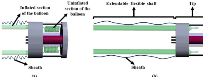
Figure 2.Schematic representation of the robot and the inflation process.(a)Uninflated robot in the initial condition,(b)inflated robot.
Figure 3. Navigation through obstacles is demonstrated. In re-gion 1, the lower balloon is inflated more in order to have a cur-vature to avoid lower obstacle. A similar procedure is followed in region 2.
sure that their distal inflated sections have contact with the tip results in a constricted continuum mechanism. This con-striction enables the robot to perform elongation, shortening and bending. Elongation and shortening can be obtained by altering the air volumes in two balloons at the same time. The axial elasticity of the balloons makes shortening possi-ble as the balloons are deflated. Bending, on the other hand, is provided by changing the air volumes in both balloons by different amounts. As an example, navigation through obsta-cles is demonstrated in Fig. 3.
Since the robot has no rigid backbone, it can easily be guided through obstacles. Moreover, exploiting the advan-tage of continuum robots, the ability to take every configu-ration in the workspace, obstacles that are already past have no effect on further navigation. This is because the balloons expand only from the distal end. The inflated section is con-stricted by obstacles and remains stationary while the tip of the robot moves forward with the increased air volume in the pneumatic actuator.
3 Cylindrical balloon model
Since the balloons, positioned in the shaft in a parallel con-figuration, constitute the backbone, all motion capabilities of
the robot depend on characteristics of individual balloons. Therefore, it is of utmost importance to understand how bal-loons behave under different loading and boundary condi-tions. The balloons used in this study can be modeled as a cylindrical membrane. If the length of the cylinder is suf-ficiently long compared to the diameter, the force balance on the cylindrical part will not be affected by the ends even though an actual balloon is closed at the ends (Müller and Strehlow, 2004). For a cylindrical element, the relation be-tween hoop stress σθ and axial stress σL is given by the well-known equationσθ=2σL. Since hoop stress is higher than axial stress, the balloon will tend to elongate rather than expand in the radial direction. The relation between ax-ial stretchλ=L/L0and hoop stretchµ=ρ/ρ0is approxi-mated by:
λ(µ)= v u u u u t
1 2
Kµ2− 1 µ2
2K+µ2 + v u u u t
1 2
Kµ2− 1 µ2
2K+µ2
2
+Kµ
−2+2
2K+µ2 . (1)
Also, pressure regarding the hoop stretchµcan be found as:
p(µ) 2|s−|d0/ρ0
= 1 λµ2
λ2− 1 λ2µ2
K+µ2, (2)
whereKis minus the ratio of elasticity coefficients−s+/s−,
ρandρ0are the current and initial radii respectively,Land L0are current and initial lengths andd0is the wall thickness of the balloon (Müller and Strehlow, 2004).
In Fig. 4, pressurep(µ) from Eq. (2) is plotted with re-spect to µ.s+ ands− are taken as 3 and−0.3 bar,
respec-tively;ρ0 is 0.32 cm andd0is 0.025 cm. It is observed that pressure becomes independent of hoop stretch for large val-ues of it. Initial peak atµ=1 occurs since the air that is first pumped in the balloon has to overcome both radial and axial stiffnesses. It is expected that pressure requirement will be less for maintaining the volume than for initial inflation.
4 Robotic system overview
Figure 4.The plot ofp=p(µ) for an extendable balloon.
Figure 5.Developed prototype and experimental setup.
is shown in Fig. 5. Two extendable balloons are placed in a radially constricted and axially flexible shaft. The tip is made of polyurethane foam. The balloons used in this study are off-the-shelf Qualatex cylindrical balloons. A typical bal-loon has an uninflated initial length of 30 cm and a diameter of 4 mm. It is manufactured from natural rubber latex. Ini-tially, the slack section remains outside of the tip, and the robot occupies approximately a 60 mm long space having a diameter of 50 mm (diameter of the tip). As the balloons are inflated, a continuous pushing force is generated at the back of the tip. Thus, the robot moves forward, and some amount of the slack section is ever so slightly retracted.
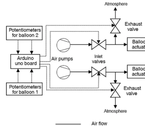
In order to control the air volume in the balloons the archi-tecture given in Fig. 6 is used. Two air pumps (Parker BTC Diaphragm) and four two-way, normally closed solenoid valves (FG Line C1) are utilized. Pumps are operated at 18 V and valves are at 12 V DC. Two potentiometers are utilized as the user interface. Since the valves are able to work only
Figure 6.Architecture used in this study.
on and off, valves are operated via Pulse Width Modulation (PWM) signals for speed control of inflation and deflation. PWM signals are generated by an Arduino Uno board at 1024 Hz. According to the value read from the potentiome-ters, each valve is assigned to one of three operating regions: on, on/off switching or off. In the on/off switching region, on and off times are controlled by pulse widths of PWM signals. Since the valves are not fast enough to track every pulse, for example very low duty cycles, their working region has been calibrated to ensure stable operation.
5 Experimental results
5.1 Balloon characterization
sig-Figure 7.Elongation behavior of the balloons for inflation and de-flation. The solid line represents the mean elongation for seven bal-loons. The shaded area is the standard error of the mean.
nificant, they were measured manually and not tracked with a sensor. Any sensor on such a soft material would distort the stress state.
Maximum elongations did not change much after second inflation. This behavior can be explained with the plasticity of the balloons. Their elasticities tend to converge in later inflations. During deflation, the positions tended to decrease almost at the same time. However, at the last stages of defla-tion, balloons sometimes went unstable as they had two lo-cal equilibrium points. This stability problem resulted in two inflated sections with a slack part in the middle. The same procedure was carried out for seven different balloons. The mean of last three repetitions was computed for each balloon. Then, the overall means and the standard errors of elonga-tion for seven balloons were calculated. The mean values are plotted with respect to time in Fig. 7, where the standard er-ror is represented as the shaded region. It was seen that the balloons expanded almost linearly. When they were close to full extension (i.e., when there was very little or no slack section left), their extending speed tended to decrease, and the extension was finally converged to a value of 124±6 cm. Deviation in this value can be explained by the differences in individual structural properties of a balloon as these local properties affect the inflation trend and the maximum length that a balloon can extend. Considering the linear regions in the inflation and deflation curves, average maximum speeds are about 3.8 and 21.0 cm s−1, respectively.
Second, in order to demonstrate the effects of different pulse widths on inflation behavior (i.e., inflation speed and pressure), a balloon was inflated with three different PWM signals; 33, 66 and 100 % duty cycles of the solenoid valves. These percentages are taken as the pulse width of the PWM signals corresponding to the highest and the lowest duty
cy-Figure 8.Elongation (a)and the pressure vs. elongation (b) of a single balloon inflated with three different duty cycles of the solenoid valves.
cles that the valves can track. Since the air pumps are al-ways operating, opening and closing of the valves are the only factors that affect the airflow into the balloons. In this analysis, the pressure was expected to remain constant af-ter a peak. However, unlike shown in Fig. 4, pressure grad-ually increased as the balloon was inflated. This discrepancy is caused by the fact that the balloon is not a perfect, constant radius cylinder. The initial peak in pressure is observed be-cause the first air that goes into the balloon has to overcome both the axial stress and the hoop stress of the rubber. Elon-gation and corresponding pressure values for a single balloon under different PWM signals are plotted in Fig. 8. It can be seen that speed of inflation decreased as lower duty cycles were employed. The inflation speeds are approximately 3.6, 3.2 and 2.34 cm s−1for 100, 66, 33 % PWM, respectively. It is also observable that the maximum longitudinal strain de-creases with lower duty cycles. Another observation is that the pressures of 33 and 66 % PWM cycles converge to almost the same value, even though there is an eight cm difference between the final elongations. This can be explained with the fact that more on-time of the valves enable the balloon to keep more air in, hence extending a little bit more.
As-Figure 9.Forces measured at the distal end of seven balloons con-stricted in a one meter long cylindrical tube.
suming full contact with the force sensor, these force values correspond to a pressure value of 24.8±3.61 kPa. It should be noted that this pressure value is slightly higher than the one in free elongation. It can be deduced that the pressure builds up as the balloon is constricted in the tube before either the balloon explodes or comes to equilibrium with increased pressure where more leakage through the system is observed. Balloons 1 and 5 exploded, which can be seen as spikes and vertical drops in the measured forces. The balloons ruptured near the inlet where they were subjected to high strains.
5.2 Workspace
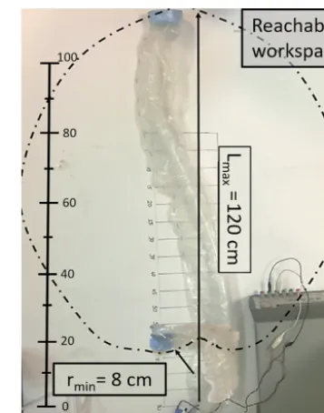
The reachable workspace of the robot is almost like an el-lipse. The maximum length the robot can reach is almost 120 cm. This length is slightly shorter than the maximum length of the balloons because some of the slack section should be attached to the tip of the robot. Therefore, this section is never inflated. The minimum radius of curvature rminis about 8 cm. However, this radius heavily depends on the initial curvature of the balloons utilized. Workspace of the robot is modeled in Fig. 10. An elliptic shape is ob-tained because the balloons are not externally constricted by an obstacle and radial constriction prevents a balloon from extending sideways just after initial inflation (when rmin is reached). Side-to-side width of the reachable workspace is about 60 cm.
5.3 Navigation experiments
Two sets of navigation experiments have been conducted as follows. In both of these experiments, the speed of inflation of the balloons was controlled manually by an operator (the first author) via potentiometers.
Figure 10.Reachable workspace, maximum reach and minimum radius of curvature of the robot. Side-to-side width of the reachable workspace is about 60 cm.
5.3.1 Open field navigation
In this experiment, the robot was navigated in an open en-vironment without any obstacles. First, the balloons were inflated together to make the robot go straight. Some rota-tions due to the structure of the balloons were encountered, but they were corrected by inflating the balloon on the same side as the curvature. Then, the robot was navigated to both sides by inflating a balloon more than the other. Straight-line movement and turning right are demonstrated in Figs. 11 and 12. Turning to left is almost identical to what is shown in Fig. 12. All trials were successful in open field navigation.
5.3.2 Maze navigation
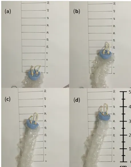
Figure 11.Robot elongating by inflating both balloons at the same time. Numbers are in cm.
6 Discussion
Results of the balloon characterization experiments showed the capabilities of the actuation system of the continuum robot. The continuum robot can extend to 1200 mm from its most contracted form which is 60 mm. This corresponds to an extension of 2000 % which is much higher than the largest strain reported in the literature (300 %) by Hawkes et al. (2016). The robot is also is able to achieve its extreme lengths quickly. When the valves are fully open, the inflation speed is about 3.8 cm s−1 and the deflation speed is around 21 cm s−1.
It is necessary to remark that five balloons ruptured during elongation experiments. Results of these balloons are omit-ted and hence not included in the analysis. Since the balloons expand only from the distal end when pressurized, the great-est amount of reaction forces arises upon contact of the tip with an obstacle. In transverse directions, the balloons are highly compliant. Therefore, axial forces are the only source of effort for the continuum robot. Determining the force ca-pabilities of the robot with respect to the input pressures is important, as they may be used to develop a better output force control method. Thus, the robot can be adapted to dif-ferent manipulation tasks. Forces that can be applied by each balloon are different due to individual structures of the
bal-loons. However, a value of 4 N can be assumed as a thresh-old that which a random balloon may explode if more force is applied. For different materials and different sized bal-loons, force-generating capability can be altered. However, such low values were expected since the balloons, therefore the robot, have no rigid backbone. This robot can be suit-able for applications where the objective is to reach a goal position and carry out tasks there with auxiliary devices that would be attached to the tip.
The navigation tests showed that the robot was success-fully controlled in open field and a maze. When the robot was navigated in open field, following a perfectly straight line was impossible since the balloons had an unpredictable slight curvature because of their structure. This is also related to the manual control of the airflow rates to the balloons and heavily depends on the skills of the operator. If one or both of the balloons have a curvature, the deviation from a straight line is immediately observable. The operator, however, could easily correct this deviation by changing the inflation speeds of each balloon. Another problem that was encountered in the navigation tests that the radius of rotation was different when the robot was rotated due to the wrinkled structure of the outer sheath. A final remark is about shortening and re-elongation of the robot. Although elasticity of the balloons brings the tip of the robot back while the balloons are de-flated, the robot will not be able to return to its initial, the most compact form without some kind of mechanism to re-tract the slack outside of the tip.
The proposed continuum robot serves as a proof-of-concept for a novel way of pneumatic actuation enabling it to be navigated through delicate and unstructured en-vironments. Further research may see this kind of actua-tion system to be employed in applicaactua-tions such as for ex-ploratory (Majidi, 2014; Tolley et al., 2014) or medical pur-poses (Cianchetti et al., 2014) if higher quality balloon actu-ators are used. The proposed design is able to tolerate much higher longitudinal strains than the examples in the litera-ture (Hawkes et al., 2016), and is maneuvered with less pres-sure than the stiffer designs (Sun et al., 2016). Please note that growth-based soft robots, such as the very-recent exam-ple calledvine robots(Hawkes et al., 2017), can lengthen by thousands of percent from the tip, too. Although the actua-tion principles are different, these robots serve to the same purpose.
Manufac-Figure 12.Robot turning to the right by inflating one balloon more than the other. Numbers are in cm.
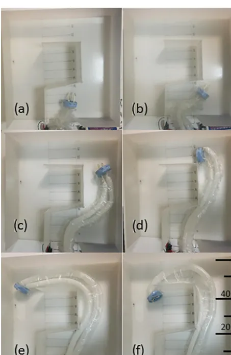
Figure 13.Robot navigating through a maze-like environment.
turing balloon actuators in an application-specific manner may also allow us to tailor balloon actuators such that the robot can be optimized for the application in mind. The shaft
design can be improved too, enabling the balloons to be con-stricted more tightly to provide better control. If a more ad-vanced material is used, it can enhance the controllability and predictability of the robot. Moreover, the inflation process is not completely reversible. The balloons can be deflated for some amount. But if it is too much, the slack section remains behind the tip and it becomes impossible to precisely control the robot. A mechanism to be located at the tip of the robot may enable recoiling of the slack of the balloons, thus mak-ing the inflation process completely reversible. Finally, some stiffening mechanism can be added to the shaft like jamming (Cheng et al., 2012) to introduce load bearing capability and robot may be made to bare transversal loads as well as the axial loads.
7 Conclusions
in applications such as medical endoscopy. Further research is underway to develop a robotic colonoscopy device at our laboratory.
Data availability. All the data and MATLAB codes can be found in a GitHub repository. Every result presented in this paper is re-producible. The link is as follows: https://github.com/eyyarbasi/ ContinuumRobot.
Competing interests. The authors declare that they have no con-flict of interest.
Acknowledgements. This work was supported by the Scientific and Technological Research Council of Turkey (TUBITAK, # 115E717).
Edited by: Chin-Hsing Kuo
Reviewed by: Yigit Menguc and one anonymous referee
References
Bishop-Moser, J., Krishnan, G., Kim, C., and Kota, S.: De-sign of soft robotic actuators using fluid-filled fiber-reinforced elastomeric enclosures in parallel combinations, in: IEEE International Conference on Intelligent Robots and Sys-tems, Vilamoura, Portugal, 7–12 October 2012, 4264–4269, https://doi.org/10.1109/IROS.2012.6385966, 2012.
Calisti, M., Giorelli, M., Levy, G., Mazzolai, B., Hochner, B., Laschi, C., and Dario, P.: An octopus-bioinspired solution to movement and manipulation for soft robots, Bioinspir. Biomim., 6, 36002, https://doi.org/10.1088/1748-3182/6/3/036002, 2011. Cheng, N. G., Lobovsky, M. B., Keating, S. J., Setapen, A. M.,
Gero, K. I., Hosoi, A. E., and Iagnemma, K. D.: Design and anal-ysis of a robust, low-cost, highly articulated manipulator enabled by jamming of granular media, in Proceedings – IEEE Interna-tional Conference on Robotics and Automation, Saint Paul, MN, USA, 14–18 May 2012, 4328–4333, 2012.
Chirikjian, G. S. and Burdick, J. W.: An obstacle avoidance algo-rithm for hyper-redundant manipulators, in IEEE International Conference on Robotics and Automation, Cincinnati, OH, USA, 13–18 May 1990, 625–631, 1990.
Chirikjian, G. S. and Burdick, J. W.: A hyper-redundant manipulator, IEEE Robot. Autom. Mag., 1, 22–29, https://doi.org/10.1109/100.388263, 1994.
Chou, C. P. and Hannaford, B.: Measurement and modeling of McKibben pneumatic artificial muscles, IEEE Trans. Robot. Au-tom., 12, 90–102, https://doi.org/10.1109/70.481753, 1996. Cianchetti, M., Ranzani, T., Gerboni, G., Nanayakkara, T.,
Althoe-fer, K., Dasgupta, P., and Menciassi, A.: Soft robotics tech-nologies to address shortcomings in today’s minimally invasive surgery: the STIFF-FLOP approach, Soft Robot., 1, 122–131, https://doi.org/10.1089/soro.2014.0001, 2014.
Cianchetti, M., Calisti, M., Margheri, L., Kuba, M., and Laschi, C.: Bioinspired locomotion and grasping in water: the soft
eight-arm OCTOPUS robot, Bioinspir. Biomim., 10, 35003, https://doi.org/10.1088/1748-3190/10/3/035003, 2015.
Conrad, B. and Zinn, M.: Closed Loop Task Space Control of an In-terleaved Continuum – Rigid Manipulator, in IEEE International Conference on Robotics and Automation, Seattle, WA, 1743– 1750, 2015.
Follador, M., Cianchetti, M., and Laschi, C.: Development of the functional unit of a completely soft octopus-like robotic arm, in: 2012 4th IEEE RAS and EMBS International Conference on Biomedical Robotics and Biomechatronics (BioRob), IEEE, 24– 27 June 2012, Rome, Italy, 640–645, 2012.
Godage, I. S., Medrano-Cerda, G. A., Branson, D. T., Guglielmino, E., and Caldwell, D. G.: Dynamics for vari-able length multisection continuum arms, Int. J. Robot. Res., 35, 695–722, https://doi.org/10.1177/0278364915596450, 2016. Grossard, M., Chaillet, N., and Regnier, S.: Flexible Robotics, John
Wiley & Sons, Inc., London, UK, 349–379, 2013.
Hawkes, E. W., Christensen, D. L., and Okamura, A. M.: De-sign and implementation of a 300 % strain soft artificial mus-cle, in: 2016 IEEE International Conference on Robotics and Au-tomation (ICRA), IEEE, 16–21 May 2016, Stockholm, Sweden, 4022–4029, 2016.
Hawkes, E. W., Blumenschein, L. H., Greer, J. D., and Okamura, A. M.: A soft robot that navigates its en-vironment through growth, Sci. Robot., 2, eaan3028, https://doi.org/10.1126/scirobotics.aan3028, 2017.
Kang, R., Branson, D. T., Zheng, T., Guglielmino, E., and Cald-well, D. G.: Design, modeling and control of a pneumatically ac-tuated manipulator inspired by biological continuum structures, Bioinspir. Biomim., 8, 036008, https://doi.org/10.1088/1748-3182/8/3/036008, 2013.
Katz, D., Pyuro, Y., and Brock, O.: Learning to Manipulate Articu-lated Objects in Unstructured Environments Using a Grounded Relational Representation, Proceedings of Robotics: Science and Systems IV, ETH Zurich, Switzerland, 25–28 June 2008, https://doi.org/10.15607/RSS.2008.IV.033, 2008.
Katzschmann, R. K., Marchese, A. D., and Rus, D.: Autonomous object manipulation using a soft pla-nar grasping manipulator, Soft Robot., 2, 155–164, https://doi.org/10.1089/soro.2015.0013, 2015.
Kier, W. M. and Smith, K. K.: Tongues, tentacles and trunks: the biomechanics of movement in muscular-hydrostats, Zool. J. Linn. Soc.-Lond., 83, 307-324, 1985.
Laschi, C., Cianchetti, M., Mazzolai, B., Margheri, L., Follador, M., and Dario, P.: Soft robot arm in-spired by the octopus, Adv. Robotics., 26, 709–727, https://doi.org/10.1163/156855312X626343, 2012.
Laschi, C., Mazzolai, B., and Cianchetti, M.: Soft robotics: Technologies and systems pushing the bound-aries of robot abilities, Sci. Robot., 1, eaah3690, https://doi.org/10.1126/scirobotics.aah3690, 2016.
Majidi, C.: Soft robotics: a perspective – current trends and prospects for the future, Soft Robot., 1, 5–11, https://doi.org/10.1089/soro.2013.0001, 2014.
Bioinspir. Biomim., 10, 35008, https://doi.org/10.1088/1748-3190/10/3/035008, 2015.
Robinson, G. and Davies, J. B. C.: Continuum robots – a state of the art, in: IEEE International Conference on Robotics and Au-tomation, 10–15 May 1999, Detroit, MI, 4, 2849–2854, 1999. Rus, D. and Tolley, M. T.: Design, fabrication and
control of soft robots, Nature, 521, 467–475, https://doi.org/10.1038/nature14543, 2015.
Sun, Y., Song, S., Liang, X. and Ren, H.: A Miniature Soft Robotic Manipulator Based on Novel Fabrica-tion Methods, IEEE Robot. Autom. Lett., 1, 617–623, https://doi.org/10.1109/LRA.2016.2521889, 2016.
at applications in space, Adv. Robotics., 29, 861–875, https://doi.org/10.1080/01691864.2015.1036772, 2015. Walker, I. D.: Continuous backbone “continuum”
robot manipulators, ISRN Robot., 2013, 1–19, https://doi.org/10.5402/2013/726506, 2013.