ISSN (Online): 2320-9364, ISSN (Print): 2320-9356
www.ijres.org Volume 1 Issue 4 ǁ August 2013 ǁ PP.01-10
Controller Gain Tuning For Road Vehicle Convoy System Using
Model Reference Adaptive Control Method
Aveen Uthman
1, Shahdan Sudin
2 1(Faculty of Electrical Engineering/ UniversitiTeknologi Malaysia, Malaysia) 2(Faculty of Electrical Engineering/ UniversitiTeknologi Malaysia, Malaysia)
ABSTRACT
:
In convoy system, the control system on each vehicle requires information about proceeding vehicle motion, in order to maintain stability and satisfy operating constraints. A two-vehicle look-ahead control strategy is proposed and investigated for the operation of a convoy. The mathematical modeling for this control strategy has been found and simulated. This paper demonstrates the design process of an adaptive controller gain for a road vehicle convoy system. This process is done by simulation. The appropriate constants are used as the reference model for the adaptive controller implementation to find the effectiveness of the control. As a result, a road vehicle convoy system with an adaptive gain controller is produced.Keywords
- two-vehicle look-ahead control strategy, model reference adaptive control, gradient approach.I.
INTRODUCTION
Nowadays, problems related to traffic congestion is dressed as issue which has to be considered. Since this issue continuously causes many accidents, traffic jams and so on. Convoys or platoons has been introduced and developed rapidly in order to overcome the collision. One of the matter which has to be taken into careful consideration in road convoy system formulation is the speed and the spacing if the following vehicle with respect to the preceding vehicle. It is important to maintain some safe distance between the following vehicle and preceding vehicle at any speed in convoy system in order to avoid any collision between both of them. Sensors are used to measure the speed and the position of the proceeding vehicle instead of estimating the information by the driver. The information which has been gotten by the sensor is used and processed by the following vehicle controller to produce the amount required speed and safe spacing distance.
In autonomous control approach, safe distance can be ensured automatically controller based on the information obtained from the preceding vehicle. The autonomous controller on the following vehicle has the ability of activating of the vehicle cruise control mode.in this case it does not need to hold the steering nor press the fuel pedal by the driver, and automatically apply the brake when necessary in order to ensure the safety of the vehicle. In fact, research in vehicle convoy has attracted the attention of several researchers in the past decades, particularly in the USA and Europe where safety, energy consumption and traffic congestions are the primary motivators. Major contributions are from the Chauffeur Project (Europe), the PATH program (USA), the Intelligent Transportation System program in Japan and the Cyber Car project in France. [1,2]In developed nations, the autonomous concept leads to the Intelligent Vehicle Highway System (IVHS).As a vehicle enters the highway, his vehicle automatically takes-over the control of the vehicle while following the preceding vehicle. This feature also gives rise to steering less technology where during the autonomous control in action, the driver does not need to hold the steering wheel. All the driving tasks are taken care by the vehicle intelligent system. One of the autonomous features is the adaptive type control based on certain control strategy which gives rise to adaptive cruise control (ACC). An ACC controlled vehicle will follow the front vehicle at a safe distance. A Model Reference Adaptive Control (MRAC) can be used in this type of control where the vehicle controller has the ability to adapt to the variation of speed and position of the preceding vehicle.[1]
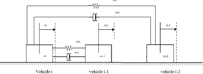
variable time‐headway policies. So from the actual diagram in Fig. 1, the vehicle following system can be represented a mass-spring-damper analogy[4] as shown in Fig. 2. A mathematical model for this control strategy is shown in Fig. 2 where irepresents the following vehicle, i-1 represents the immediate preceding vehicle, and i-1 represents the vehicle which is in front of preceding vehicle. The parameters in the above figure are vehicle mass (m),vehicle displacement (x), vehicle acceleration ( ), spring constant (kp) and damper constant (kv). The interest is only on the following vehicle. So, performing the mathematical modeling on only the following vehicle i and applying the Newton’s Second law results in the following Eq. (1).
m i= Kp1 (xi-1- xi) + Kp2 (xi-2-xi) + kv1( i-1 - i) + Kv2 ( i-2- i)(1)
Assuming unit mass for Eq. (1) and taking Laplacetransform, gives the following transfer function.Xi=
(2)
The transfer function in Eq. (2) depends on the followingspacing policy.
The aim of this strategy is to maintain string stability forlongitudinal motion within the vehicle following system orthe vehicle convoy, particularly between a vehicle with avehicle or between vehicles with a following vehicle. Thisstrategy is adopted in order to design a controller byinvestigating the following two policies
III.
SPACING
POLICY
A spacing policy is defined as a rule that dictates how the speed of an automatically controlled vehicle must regulate as a function of the following distance. A control system should be designed such that it regulates the vehicle speed according to the designed spacing policy.[5]
1. Fixed Distance Spacing Policy
Figure 2. A mathematical model of a vehicle convoy system control strategy.
2. Fixed Time Headway Policy
This policy use a constant time interval of inter-vehicular spacing, called time headway between the following vehicle and preceding vehicle. It is a speed dependent policy where the inter-vehicular spacing will vary according to the preceding vehicle speed. At higher speed, vehicles will be separated in a greater distance but always maintains a fixed time interval between vehicles. Most researchers used this spacing policy in designing controllers to ensure string stability as this policy mimics the behavior of human drivers. As vehicle speed is increased, a human driver will keep a safe inter-vehicular spacing with the immediate preceding vehicle.
The performance of the fixed headway spacing policy used in autonomous and cooperative vehicles following systems has been studied. It is found that there exists minimum possible fixed headway spacing before the string stability of convoy collapses, which is related to the actual dynamics of the vehicle. The effect of this fixed headway spacing policy is equivalent to the introduction of additional damping in the transfer function, which allows the poles of the transfer function to be moved independently from the zeros of the same transfer function. With the addition of the fixed headway spacing, Eq. (2) then becomesXi=
(3)
and the control law developed as:
ui=Kp1 (xi-1-xi -h i) +Kp2 (xi-2-xi-2h i) +kv1( i-1 - i) +Kv2 ( i-2- i) (4)
Equation (4) can be re-arranged and reduced to a single pole system as follows,
Xi=
(5)To simplify the control law and at the same time ensurestability, a
pole-zero cancellation technique is chosen. Thiscan be achieved by introducing the constraint
(6) This reduces equation (5) to Xi=
(7)
This is a first order system. Since K v1
and K v2
are always positive, the pole of equation (7) is always on the
left hand side of the s-plane and the system is always stable under the constraint of equation (6). Hence, the mathematical model of the proposed vehicle convoy system in equation (4) is string stable under the constraint of equation (6).
3. Vehicle Dynamic Consideration
Figure 4. Block diagram consisting of the control strategy and vehicle dynamics
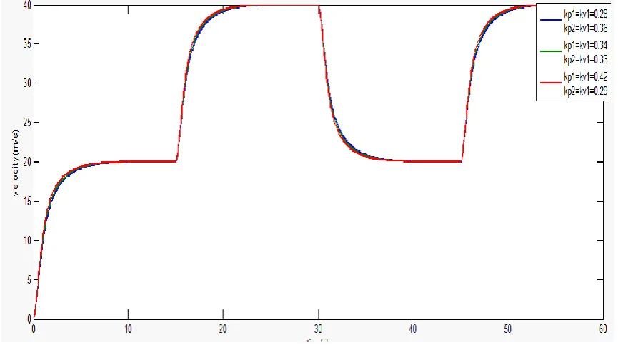
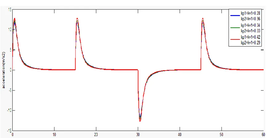
Eq. (10) is then simulated by using MATLAB Simulink. The controller block in Figure 4.6 contains two-vehicle look-ahead control strategy. The circuit is then simulated with the set values of h=1s with the values of kp1 which is equal to kv1 set as 0.28, 0.34, and 0.42 respectively and Kp2 which is equal to Kv2 set 0.36,0.33 and 0.29 respectively .The results are shown in Figures 4.7 and 4.8,. There are some ripples or oscillations observed in the speed and acceleration plots. It is found that the values of kp1=0.28 and Kp2=0.36 are still found to give the best result. This is still acceptable as the plots somehow show the real situation when the vehicle internal dynamics is taken into consideration.
Figure 6. Acceleration response with fixed time headway for various kp and kvvalues and vehicle dynamics
IV.
M
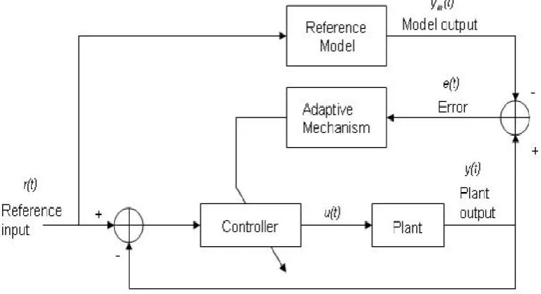
ODEL REFERENCE ADAPTIVE CONTROLAn adaptive controller can modify its behavior in response to changes in the dynamics of a system and the character of any disturbance. It is a controller with adjustable parameter and a mechanism for adjusting the parameter. An adaptive control system consists of two loops, normal feedback loop with plant and controller and an adaptive parameter mechanism loop. Figure 5.1 illustrates the general structure of the Model Reference Adaptive Control (MRAC) system. The basic MRAC system consists of four main components: i) Plant to be controlled
ii) Reference model to generate desired closed loop output response
iii) Controller that is time-varying and whose coefficients are adjusted by adaptive mechanism
iv) Adaptive mechanism that uses ‘error’ (the difference between the plant and the desired model output) to produce controller coefficient.
Regardless of the actual process parameters, adaptation in MRAC takes in the form of adjustment of some or all of the controller coefficients so as to force the response of the resulting closed-loop control system to that of the reference model.
Therefore, the actual parameter values of the controlled system do not really matter.
1. The Gradient Approach
The Gradient Approach of designing an MRAC controller is also known as the MIT Rule as it was first developed at the Massachusetts Institute of Technology (MIT), USA. This is the original approach developed for adaptive control design before other approaches were introduced to overcome some of its weaknesses. However, the Gradient approach is relatively simple and easy to use. In designing the MRAC controller, we would like the output of the closed-loop system (y) to follow the output of the reference model (ym). Therefore, we aim to minimize the error (e=y-ym) by designing a controller that has one or more adjustable parameters such that a certain cost function is minimized.
V.
ADAPTIVE CONTROLLER GAIN DESIGNAn adaptive controller gain is to be designed for the two vehicle look-ahead control strategy with fixed time headway and vehicle dynamics by applying a Model Reference Adaptive Control (MRAC). This section presents a direct adaptive controller design which adapts the unknown vehicle parameters kp1 and. Kp2 The advantage of the adaptive approach is that unpredictable changes in the value of kp1 and kp2 can be easily accommodated. From the analysis of Figure 4.2 and Figure 4.3, kp1=kv1=0.28 and kp2=kv2=0.36 give the best response. So, it will be used in equation (10) to produce a reference model in equation (11) to be used in designing the adaptive controller gain. The vehicle dynamic has been included in the control law to form the plant. the reference model is represented as in eq. (11).
Figure 7 .General structure of an MRAC system
(12) And the reference model is:
(13)
r(t) = Reference input signal u(t) = Control signal y(t) = Plant output
ym(t) = Reference model output
e(t) = Difference between plant and reference model output = y(t) - ym(t)
e =y – ym
e=
In this case we need to do some approximation: i.e. perfect model following, y m=y .Therefore, we then have,
= and, ,
As a result:
And,
(15)
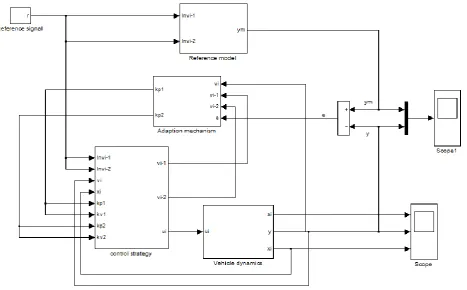
Figure (8) shows the simulation block diagram of gradient approach adaptive control used for tuning of controller gains (kp1 and kp2).
Figure 8.The gradient approach adaptive gain controller simulation diagram
Figure 9. Simulation diagram of adaptive mechanism
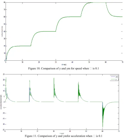
Figure 10. Comparison of y and ym for speed when is 0.1
Figure 11. Comparison of y and ymfor acceleration when is 0.1
Figure12. Comparison of y and ym for speed when is 0.0001
Figure 13. Comparison of y and ym for acceleration when is 0.0001
It can be said that better range of gamma values should be between 0.1 and 0.0001 in order to get acceptance simulation result.
As aresult, A two-vehicle look-ahead control strategy with fixed headway policy has been adopted to design a controller to produce an output, which can respond immediately to the change in input; in this case, the input is the speeds of two- vehicle look ahead with varying speed conditions. With normal controller, the response does not quite follow the input. With the introduction of the MRAC adaptive controller gain, the response can be made to follow the input when suitable reference model is chosen. Moreover, using MRAC adaptive controller gain produces a smooth output as compared to the other one.
VII.
C
ONCLUSIONElectrical Engineering, Universiti Teknologi Malaysia, Skudai Johor.He received his M.Sc.E.E.in control and optimization from UTM in 1994 and PHD from the University of Manchester, United Kingdom in
2005.
He has morethan13 years experiences in
the field of his proposed project (
Dynamics and Control of Chapter 1 Vehicle Convoy Systems). His research interest includes control and optimization especially dynamic and control of vehicle convoy system and the stability of vehicle/following system as well.University, Iraq in 2007.She is currently master student of Mechatronics and Automatic Control Engineering program at Faculty of Electrical Engineering, Universiti Teknologi Malaysia (UTM), Skudai, Johor, Malaysia. She is a member staff in control lab. at Sulaimani Technical College, Kurdistan Region, Iraq
R
EFERENCES[1] Ng, T.C., J.I. Guzman, and M.D. Adams. Autonomous vehicle-following systems: A virtual trailer link model. in Intelligent Robots and Systems, 2005.(IROS 2005). 2005 IEEE/RSJ International Conference on. 2005: IEEE.
[2] Cerone, V. and D. Regruto, Bounding the parameters of linear systems with input backlash. Automatic Control, IEEE Transactions on, 2007. 52(3): p. 531-536.
[3] Sudin, M.R.S., Shahdan, and M. Sapiee, Road Vehicle Following System With Adaptive Controller Gain Using Model Reference Adaptive Control Method. 2009.
[4] Cook, S.S.a.P.A., Dynamics of Convoy Control Systems with Two-Vehicle Look-Ahead Strategy. International Conference on Robotics, Vision, Information and Signal Processing, 2003. pp. 327-332.
[5] Yanakiev, D. and I. Kanellakopoulos. A simplified framework for string stability analysis in AHS. in Proceedings of the 13th IFAC World Congress. 1996.
[6] Sudin, S., Dynamics And Control Of Vehicle Convoy System. PhD Thesis.School of Electrical and Electronic Engineering, Faculty of Engineering and Physical Sciences, The University of Manchester., 2005.
[7] Darbha, S. and K.R. Rajagopal, Intelligent cruise control systems and traffic flow stability. Transportation Research Part C: Emerging Technologies, 1999. 7(6): p. 329-352.
[8] Shladover, S.E., Longitudinal control of automated guideway transit vehicles within platoons. Journal of Dynamic Systems, Measurement and Control, vol. 100 no. 4, 1978.
[9] Sudin, S. and P.A. Cook. Two-vehicle look-ahead convoy control systems. in Vehicular Technology Conference, 2004. VTC 2004-Spring. 2004 IEEE 59th. 2004: IEEE.
Aveen Uthman sheobtained her bachelor’s degrees in Mechatronics engineering from Baghdad
Shahdan Sudinis a senior lecturer in the Department Control and Mechatronics Engineering, Faculty of