ISSN (e): 2250-3021, ISSN (p): 2278-8719 Vol. 09, Issue 6 (June. 2019), ||S (I) || PP 45-52
Mathematical And Simulation Models Of Lighting Automatic
Control System In According With Natural Light
NGO Phuong Le, LUONG Ngoc Giap,
NGUYEN Binh Khanh, BUI Tien Trung, TRUONG Nguyen Tuong An
Institute of Energy Science, Vietnam Academy of Science and Technology A9 Building, 18, Hoang Quoc Viet str., Cau Giay dist., Hanoi, Vietnam
Corresponding Author:NGO Phuong Le
Abstract: This article presents a mathematical model and a simulation model of lighting automatic control system in according with natural light to achieve standard illuminance and energy saving. The paper presents a method to develop mathematical models of actuators (LED driver and LED), sensor (light dependant resistor and analog-digital converter). PID controller with consideration of integral anti-windup to improve regulation quality of the system was introduced. Simulation model was constructed on Matlab-Simulink to verify mathematical model and to evaluate quality of regulation.
Keywords: Mathematical model, simulation model, lighting, automatic control, LED, LDR, matlab, simulink. --- Date of Submission: 27-05-2019 Date of acceptance: 13-06-2019 ---
I. INTRODUCTION
Lighting system consumes a large amount of electricity in the total energy demand of buildings. According to statistics, electricity used for lighting in the whole world accounts for about 19-20% of the total global electricity consumption [1,2]. Therefore, economical and efficient use of energy in lighting is of interest in many countries.
In recent years, LEDs (Light-emitting diode) are growing very fast. LED lights save 50-70% more energy than traditional lamps and the price is decreasing. LEDs also make dimming easier than traditional lamps [3]. LEDs open up many new possibilities in smart lighting.
Smart lighting to bring comfort, energy saving by automatic turning light on/off depending on occupation or automatic regulating light brightness depending on natural light. It is necessary to have an automatic control system in smart lighting. In [4], the system automatically counts people in / out of the room and turns on and off the lights. [5] presents an automatic headlight dimmer which uses a Light Dependent Resistor (LDR) sensor to dim the headlight and switch from high beam to low beam to prevent glare for the opposite car.
An lighting automatic control system consists of 3 parts: the controller; sensors; and actuators. Adaptive dimming control is used in [6] to control both lamps and blinds to take advantage of outdoor lighting, saving electricity while reducing heat and glare. In [7] the authors assessed the interaction between illuminated areas, built a MIMO model (multiple inputs, multiple outputs) from experiments. However, detailed mathematical model for each part of the control system has not been studied much.
In this paper, we will present methods to build mathematical models of sensors, actuators in lighting control system; methods to synthesize PID controller with consideration of integral anti-windup; a simulation model and evaluate results.
II. MATHEMATICAL MODELS
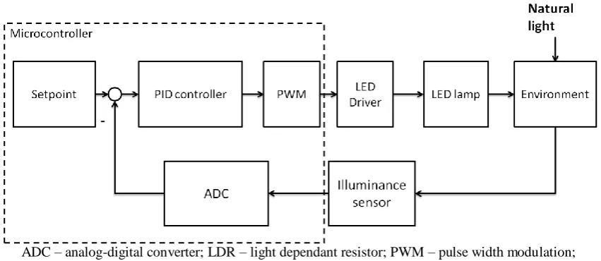
ADC – analog-digital converter; LDR – light dependant resistor; PWM – pulse width modulation; Figure 1. Lighting automatic control schematic in according to natural light
A. Mathematical model of actuator
Actuator consists of pulse width modulation module (PWM), LED driver and LED. LED driver supplys the LED lamp with output current, which is proportional to PWM control signal. The transfer function of PWM, LED driver can be presented as an amplifier with delay. However, theses are semiconductor elements with very small delays: PWM about 10ns, LED driver about 200ns.
LED lamps have a typical current to luminous flux characteristic as shown in Figure 2 [8]. The current-luminous flux characteristic is linear, and given that current is proportional to control signal u, thus the luminous flux generated by LED lamp is also proportional to output control signal .
Figure 2. Typical current-luminous flux characteristic of a LED lamp
The lighting environment considered in this system is consisted of a LED lamp, a working plane and natural light.
Let S be a point source of luminous flux and P is a point on the working plane receiving the luminous radiation from S. If Let I be the luminous intensity of the radiation. The illuminance at the point P is:
(1) Where – angle between normal to the surface and the luminous ray from S to P; – distance between S and P. Formula (1) can not be used directly since LED lamp can not be considered as a point source of light. However, we can consider a LED lamp as a set of point sources of light. The resulting illuminance in a given point of the given surface is the sum of illuminances due to each point source of light:
(2)
Note that (1) shows a linear relationship between and I. However, from the modelling perspective, relationship between illuminance and luminous flux is of interest. From the definition of luminous intensity, which is equal to in a solid angle , it means luminous intensity I is proportional to overall luminous flux . It means that is proportional to overall luminous flux .
To summarize, group of PWM, LED driver and LED in the considered lighting environment can be modelled as a proportional K1, of which input is control signal PWM and output is illuminance at point P on the given working plane.
B. Mathematical model of LDR and ADC
The LDR has a resistance-illuminance characteristic as shown in Figure 3 [8]. This relation is linear at the logarithmic scale, the equation reflecting the relationship between the resistance R of the LDR and the illuminance L is:
(3)
Where – resistance of the LDR; – illuminance on the surface of LDR; – resistance of LDR corresponding to illuminance ; – resistance of LDR corresponding to illuminance ;
The values of , , , can be retrieved from the datasheet and be corrected with experiments. Transform (3), move to the left:
(4)
Name the parameters:
Raise both side to 10th power, we have the function of R of :
(5)
Figure 3. Resistance-illuminance characteristic of LDR
Figure 4. LDR in electrical circuit
Figure 4 shows circuit schematic of LDR. Voltage input to ADC pin of microcontroller depends on resistance of LDR as following:
(6)
Where – voltage of supply power of the microcontroller; – resistor connected in series with LDR to divide voltage.
If ADC has a resolution of n-bit, the digital value that ADC converted from input voltage is:
(7)
Combine (6) and (7), we get:
(8)
Instead of using direct value a read from ADC, we use as feedback signal to the PID. Substitute (8) to the expression of y:
Substitute (5) to (9), we get:
(10)
Use the parameters from datasheet of LDR: , , , ; try the pullup resistor (in the circuit in Figure 4) with 4 different values: , , , ; we get a curves as shown on Figure 5.
Figure 5. Relationship between y and lgL in cases , , , According to the lighting standards for work place (TCVN 7114 - 1 : 2008 và ISO 8995 - 1 : 2002), minimum required illuminance is 300 lux, therefore we can consider only the range 10 lx < L < 1000 lux, or . Figure 6 presents the linearization of curves with the equations of lines corresponding to each curve (Note: x = ).
Figure 6. Curves y of lgL on the range and linearized lines in 4 cases: , ,
Value on Figure 6 is coefficient of determination, which is a statistical measure of how well the regression predictions approximate the real data points. We can use this index to choose the most appropriate value of resistor , so that linearization yields the best result. With , is the biggest value of all, equals 0,997, and equation of linearized line is:
(11)
Thus, LDR and ADC can be modelled as a first-order lag
(12)
Where from linearized line; is time constant, modelling the rise time/fall time of LDR and the conversion time of ADC.
C. PID controller
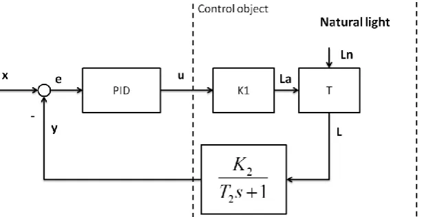
With the mathematical models of the sensor and actuator, the diagram on Figure 1 now can be presented as diagram of transfer functions on Figure 7.
K1 – proportional part corresponding to a group of PWM, LED driver and LED; , – parameters of first-order lag, modelling a group of LDR and ADC; T – process mixing natural light and artificial light; x – set point; y – feedback signal; u – control signal; La – illuminance by artificial light; Ln – illuminance by natural
light; L – sum of illuminances;
Figure 7. Light automatic control system in form of transfer functions
The process T of mixing natural light and artificial light is a complicated process, which is depends on how the sensor is placed, the direction of natural light, the color of the ceiling surface, walls, floor, etc. However in our considered lighting environment, this process can be modelled as a simple sum. Natural light is considered to be a load disturbance.
Blocks K1, K2, T are grouped as control object with transfer function::
(13)
PID controller’s transfer function is as following:
(14)
Where – proportional term; – integral term; – derivative term; – Laplace operator.
In practice, derivative term is rarely used because it is very sensitive to noise and can worsen stability of the system. Thus, only PI controller is used, meaning :
(15)
Due to the ideal output being physically impossible (actuator’s limitations), the output of the controller must being limited with a saturation block:
(16)
Where – lower limit of the controller; – upper limit of the controller.
Integral term in the controller helps to eliminate the static error of closed loop, but also brings integral windup when output saturation is used. The integral term accumulates a significant error, thus overshooting. When output saturation is used, overshoot can be smaller but the transient time is longer.
add the result to the integral term output in the controller. The diagram of PI controller with saturation block and integral anti-windup component is presented on Figure 8.
- proportional term; – integral term; – output signal before saturation block; – output signal after saturation block; – error between signal before and after the saturation block; – coefficient of integral
anti-windup.
Figure 8. Diagram of PI controller with saturation block and integral anti-windup component III. SIMULATION MODELS
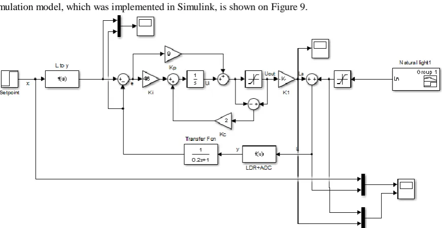
Simulation model, which was implemented in Simulink, is shown on Figure 9.
Figure 9. Simulation model of lighting automatic control system in according with natural light Symbols on Figure 9 are as following:
LDR+ADC: Light dependant resistor and analog-digital converter with static characteristic described by (10); followed by a first-order lag transfer function to simulate of rise/fall time of LDR;
K1: PWM, LED driver and LED in considered lighting environment create illuminance La
Natural light: a signal generator to simulate varying natural light with illuminance Ln. Simulation script is as following:
- Setpoint is 300lx at t=0s then increases to 800lx at t=20s;
- Natural light is 1lx at t=0s, increases to 400lx at t=10s, to 1000lx at t=25s, down to 200lx at t=40s, and to 1lx at t=50s
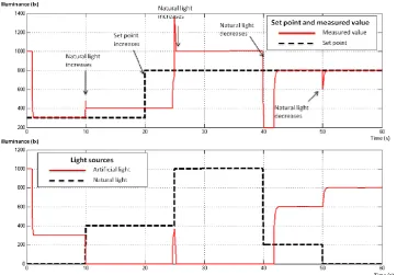
Simulation results show that the system with integral anti-windup react better to the changes in setpoint and natural light. Control system without anti-windup is saturated in many points, and doesn’t react to the change of setpoint (at t=20s, Figure 10) or change of natural light (at t=40s, Figure 10).
Figure 10. Simulation results of lighting automatic control system WITHOUT integral anti-windup
Figure 11. Simulation results of lighting automatic control system WITH integral anti-windup Table 1. Comparison between control systems with and without integral anti-windup
Performance index Without integral
anti-windup With integral anti-windup
Transient time 5s 0.5s
Overshoot 0% 0%
IV. CONCLUSION
The article described the construction of mathematical models of each equipment in the lighting automatic control system in according with natural light. The models were built based on the characteristics of actuator and sensor (LED lamp, LDR) and peripherals of microcontroller (PWM, ADC). The paper has proposed: (1) a formula to transform measured value from ADC before feeding to the controller; (2) a method to choose pullup resistor, which connected in serie with LDR, so that linearity of the measurement can be as high as possible.
A simulation model was implemented in Simulink. Simulation results show that the system with integral anti-windup react better to the changes in setpoint and natural light. The transient time is less than 0,5s, which is good enough for a lighting system.
This is the first part of a research project about smart lighting for classroom in Viet Nam. The project aims to develop a network of intelligent LED lamps, which allows to separately control each LED lamp in the classroom with consideration of natural light and the interraction with each other. The next step of the project is to develop mathematical and simulation models of this system and to implement the control algorithm as embedded software in microcontroller to assess the mathematical and simulation models.
REFERENCES
[1]. Concepts and Techniques for Energy Efficient Lighting Solutions. Eino Tetri, Helsinki Universityof Technology Wilfried Pohl, Bartenbach LichtLabor, 2008.
[2]. Hawaii Commercial Building Guideline for energy efficiency. Daylighting Guideline. ©2003 EleyAssociates on behalf of State of Hawaii DBEDT.
[3]. Khanna, V.K. (2014). Fundamentals of Solid-State Lighting: LEDs, OLEDs, and Their Applications in Illumination and Displays. Taylor & Francis. pp. 475–488. ISBN 978-1-4665-6109-0. Retrieved February 10, 2015.
[4]. Md. Saddam Hossain, Helal-An-Nahiyan. Automatic Control System for Lighting of a Single Door Room with Bidirectional People Counter
[5]. OKRAH. S.K WILLIAMS. E.A KUMASSAH. F. Design and implementation of automatic headlight dimmer for vehicles using light dependent resistor (ldr) sensor / International Journal of Emerging Technology and Innovative Engineering Volume 2, Issue 4, April 2016 (ISSN: 2394 – 6598).
[6]. S.G. Colaco, C.P. Kurian, V.I. George, and A.M. Colaco. Integrated design and realtime implementation of an adaptive, predictive light controller. Lighting Research & Technology, 44:459{476, 2012.
[7]. R. De Keyser and C. Ionescu. Modelling and simulation of a lighting control system.System Modelling Practice and Theory, 18:165{176, 2010.
[8]. Multicomp’s 1 W High Power LED datasheet.
[9]. S.Y. Ron Hui and Y.X. Qin. A general photo-electro-thermal theory for light emitting diode (led) systems. IEEE Transactions on Industrial Electronics, 24:1967-1976, 2009.
[10]. Suncom Light Dependant Resistor – LDR datasheet, model #3190.
NGO Phuong Le. “Mathematical And Simulation Models Of Lighting Automatic Control System In According With Natural Light.” IOSR Journal of Engineering (IOSRJEN), vol. 09, no. 06, 2019, pp. 45-52.