VOLUME 3, ISSUE 7, July-2017
IMPLEMENTATION OF A NEW 7-LEVEL H-BRIDGE INVERTER FED
INDUCTION MOTOR WITH LOW HARMONIC VALUES
MR. YOGESH S. BAIS
Ph.D. Scholar, Electrical Department, Priyadarshini college of Engineering, Nagpur, India [email protected]
DR. S.B. DESHPANDE
Professor in Electrical Engg. and Dean R & D, Priyadarshini Institute of Engg. and Technology, Nagpur, India [email protected]
DR. S.P.MULEY
HOD, Electrical Engg. Department, Priyadarshini college of Engineering, Nagpur, India [email protected]
ABSTRACT:
A Multilevel structure with more than five levels can significantly reduce the harmonic content. The output voltage and power increase with number of levels. Adding a voltage level involves adding a main switching device to each phase.
The goal here is to implement the seven level H-Bridge inverter with less number of switches. The output of this circuit is fed to the induction motor. Using this scheme, we can control the speed and also reduce the noise and vibration of the Induction motor. This research stresses on improving the efficiency of multilevel inverter and quality of output voltage waveform. A new seven level scheme is implemented with only seven switches. The MATLAB simulation is done and hardware is implemented by using IGBT's for the seven switches of seven level inverter.
KEYWORDS: IGBT, Multilevel inverter, H-Bridge, Induction motor, etc.
I. INTRODUCTION:
Multilevel converters can be applied to utility interface systems and motor drives. These converters offer a low output voltage THD, and a high efficiency and power factor. There are three types of multilevel converters: (1) diode clamped, (2) flying capacitors, and (3) cascaded. The main advantages of multilevel converters include the following : a) They are suitable for high-voltage and high current applications.
b) They have higher efficiency since the devices can be switched at a low frequency.
c) Power factor is close to unity for multilevel inverters used as rectifiers to convert ac to dc.
d) No Electromagnetic Interference (EMI) problem exists. e) No charge unbalance problem results when the converters are in either rectification or inversion mode. The multilevel converters require balancing the voltage across the series-connected dc bus capacitors. Capacitors tend to overcharge or completely discharge, at which condition the multilevel converter reverts to a three-level
converter unless an explicit control is devised to balance the capacitor charge. The voltage-balancing technique must be applied to the capacitor during the operations of the rectifier and the inverter. Thus, the real power flow into a capacitor must be the same as the real power flow out of the capacitor, and the net charge on the capacitor over one cycle remains the same.
II. LITERATURESURVEY:
In the paper [1], two types of methods or topologies have been compared i.e. cascaded and reduced switches topology. Out of these two, this research uses reduced switches topology.
In the paper [7], the THD contents of 7, 11 and 15 level cascaded multilevel inverters have been discussed. The total harmonic distortion depends on the switching angles for different units of multilevel inverters; hence, the switching angles are calculated first by using Newton-Raphson method where some of harmonic components have been eliminated. Using the calculated switching angles, THD analysis is carried out analytically as well as using MATLAB simulation.
The paper [20] demonstrates how the reduced harmonic distortion can be obtained for a new topology of multilevel inverters. The new topology has the advantage of its reduced number of devices compared to conventional cascaded H-Bridge multilevel inverter and can be extended for any number of levels. Here, the harmonic reduction is obtained by selection of appropriate switching angles.
The paper [21] deals with the analysis and simulation of the seven level inverter. The percentage total harmonic distortion is calculated for seven level inverter. The functionality verification of seven level inverter is done using MATLAB.
III. REDUCED SWITCHES SCHEME:
VOLUME 3, ISSUE 7, July-2017 nearly sinusoidal output voltage waveform. A key issue in
the fundamental switching scheme is to properly and carefully determine the switching angles for producing the voltage with fundamental frequency.
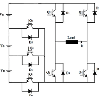
Fig. 1 Power circuit with only 7 switches for 7-level output.
There are 3 modes of operation of this 7-level inverter. These modes are described in details as below.
A. POWERING MODE :
This mode of operation occurs when both the load current and voltage have the same polarity. During the positive half cycle, when the output voltage is Vdc, the path of flow of current consists of: the lower supply, D6, Q1, load, Q4 and back to the lower supply.
When the output voltage is 2Vdc, the path of flow of current is: the lower source, Q5, the upper source, Q1, load, Q4 and back to the lower source.
When the output voltage is 3Vdc, the path of flow of current comprises: upper supply, Q1, load, Q4, Q7, lower supply. During the negative half cycle, the switches Q1 and Q4 are replaced by the switches Q2 and Q3 respectively.
B. FREE-WHEELING MODE:
Free-wheeling mode occurs when one of the main switches is turned off while the load current needs to continue its flow due to the load inductance. This feature is obtained with the help of anti-parallel diodes across the switches and the load circuit is disconnected from the source terminals.
In this mode of operation, the positive half cycle current flow comprises: Q1, load and D2 or Q4, load and D3. Whereas in the negative half cycle, the current flow path includes: Q3, load and D4 or Q2, load and D1.
C. REGENERATING MODE:
During this mode of operation, part of the energy stored in the load inductance is returned back to the source. This occurs during the intervals when the load
current is negative during the positive half cycle and vice-versa. During this period, the output voltage is zero.
The positive current flow path consists of: load, D2, Q6, the lower source and D3. While the negative current flow path consists of: load, D1, Q6, the lower source and D4.
Fig. 2 Waveforms of the 7-level inverter under consideration.
IV. SELECTIVE HARMONIC ELIMINATION:
The Selective Harmonic Elimination Stepped Waveform (SHESW) technique is suitable for a 7-level inverter circuit. Employing this technique along with the multilevel topology, the low Total Harmonic Distortion (THD) output waveform without any filter circuit is possible.
(A) FOURIER SERIES AND HARMONICS ELIMINATION THEORY:
After applying Fourier theory to output voltage waveform of multilevel converters, which is odd quarter-wave symmetric, we can find the Fourier expression of multilevel output voltage as given by equation (1). If the DC voltages are equal in multilevel converter, the equation for the fundamental frequency switching control method can be given as:
V(t) = Σ∞n=1,3,5….4Vdc/ nπ (cos(nθ1) (cos(nθ2)+ (cos(nθ3)+...+ (cos(nθs)) sin (nωt) ...(1)
From this equation, it is seen that the output voltage has no even harmonics because output voltage waveform is odd quarter-wave symmetric. It also can be seen from equation (2) that peak values of these odd harmonics are expressed in terms of the switching angles θ1, θ2, and θs. Also, the harmonic equations produced from (2) are transcendental equations.
Depending on the harmonic elimination theory, if we want to eliminate the nth harmonic, then
cos (nθ1) +cos (nθ2) +…. +cos (nθs) =0 ... (2)
VOLUME 3, ISSUE 7, July-2017 the 's' different harmonic values. Generally, an equation
with 's' switching angles is used to determine the fundamental frequency value, and to eliminate 's-1' low order harmonics. For an equation with three switching angles, equation (2) becomes
V (t) = Σ∞n=1, 3, 5….4Vdc/nπ (cos (nθ1) + (cos (nθ2) + (cos
(nθ3)) sin (nωt) ... (3)
(B) TRANSCENDENTAL EQUATIONS TO SOLVE:
Here, we derived harmonic equations for eliminating the 3rd and 5th order harmonics. The resulting harmonic equations are as follows:
cos θ1 + cos θ2 + cos θ3 = πV1/ 4Vdc ... (4) cos 3θ1 + cos 3θ2 + cos 3θ3 = 0 ... (5)
cos 5θ1 + cos 5θ2 + cos 5θ3 = 0 ... (6)
To simplify the expression, equation (4) can be written as
cos θ1 + cos θ2 + cos θ3 = m ... (7) where m = πV1/ 4Vdc ... (8)
These harmonic equations (4) to (6) are transcendental equations. They are difficult to solve without using some type of numerical iterative technique. Here Newton Raphson method is employed for solving these equations.
(C) SOLVING THE HARMONIC EQUATIONS USING NEWTON RAPHSON METHOD:
To solve the harmonic equations by resultant theory, they must be changed into polynomials. First, we change the variables,
x1 = cos(θ1) (9)
x2 = cos(θ2) (10) and x3 = cos(θ3) (11)
Also, use the following trigonometric identities:
cos 3θ = 4cos3 (θ) − 3cos (θ) (12) cos 5θ = 5cos θ − 20cos3 θ + 16cos5 (θ) (13)
Then, apply them to the transcendental harmonic
equations above, and the following polynomial harmonic equations can be found.
For the fundamental frequency harmonic: P1(x1, x2, x3) = Σ3n=1 (xn– m) = 0 (14)
For the 3rd harmonic:
P1(x1, x2, x3) = Σ3n=1 (4xn3 − 3xn) = 0 (15) For the 5th harmonic:
P1(x1, x2, x3) = Σ3n=1(5xn− 20xn3 + 20xn5) = 0 (16)
The polynomial equations can be solved by using the Newton Raphson method. The following are steps for solving the equations. Substitute the initial guesses for variables. Then form the jacobian matrix with Newton’s formula. Repeat the same steps until the solutions to converge. Thus, the switching angles θ1, θ2 and θ3 are obtained as follows:
θ1 = 8.766 ° θ2 = 28.688 ° θ3 = 54.939 °
From the fig. 2, the switching patterns for switches Q1 to Q7 become clear. Here, the fundamental frequency switching scheme is employed, which drastically reduces the switching losses.
Switching losses are directly proportional to the switching frequency. In this method the switching frequency is less as compared to the other methods and hence the switching losses are less which is a bigger advantage.
V.CIRCUITDIAGRAM:
VOLUME 3, ISSUE 7, July-2017
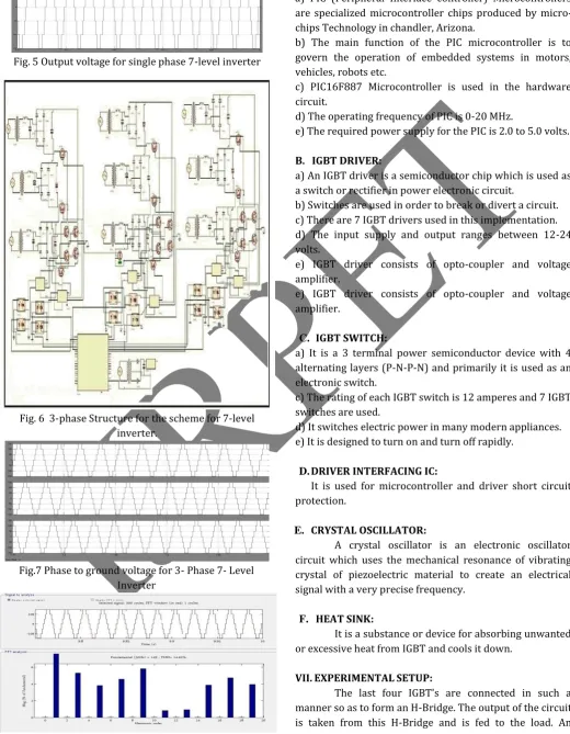
Fig. 5 Output voltage for single phase 7-level inverter
Fig. 6 3-phase Structure for the scheme for 7-level inverter.
Fig.7 Phase to ground voltage for 3- Phase 7- Level Inverter
Fig. 8 FFT Analysis
VI. COMPONENTS AND THEIR FUNCTIONS: A. PIC MICROCONTROLLER:
a) PIC (Peripheral Interface controller) Microcontrollers are specialized microcontroller chips produced by micro-chips Technology in chandler, Arizona.
b) The main function of the PIC microcontroller is to govern the operation of embedded systems in motors, vehicles, robots etc.
c) PIC16F887 Microcontroller is used in the hardware circuit.
d) The operating frequency of PIC is 0-20 MHz.
e) The required power supply for the PIC is 2.0 to 5.0 volts.
B. IGBT DRIVER:
a) An IGBT driver is a semiconductor chip which is used as a switch or rectifier in power electronic circuit.
b) Switches are used in order to break or divert a circuit. c) There are 7 IGBT drivers used in this implementation. d) The input supply and output ranges between 12-24 volts.
e) IGBT driver consists of opto-coupler and voltage amplifier.
e) IGBT driver consists of opto-coupler and voltage amplifier.
C. IGBT SWITCH:
a) It is a 3 terminal power semiconductor device with 4 alternating layers (P-N-P-N) and primarily it is used as an electronic switch.
c) The rating of each IGBT switch is 12 amperes and 7 IGBT switches are used.
d) It switches electric power in many modern appliances. e) It is designed to turn on and turn off rapidly.
D. DRIVER INTERFACING IC:
It is used for microcontroller and driver short circuit protection.
E. CRYSTAL OSCILLATOR:
A crystal oscillator is an electronic oscillator circuit which uses the mechanical resonance of vibrating crystal of piezoelectric material to create an electrical signal with a very precise frequency.
F. HEAT SINK:
It is a substance or device for absorbing unwanted or excessive heat from IGBT and cools it down.
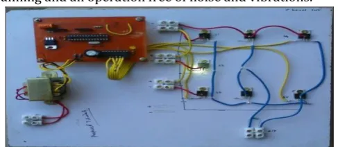
VII. EXPERIMENTAL SETUP:
VOLUME 3, ISSUE 7, July-2017 induction motor is used as a load which gives a smooth
running and an operation free of noise and vibrations.
Fig. 9 Experimental setup of the 7-level inverter circuit.
Fig. 10 Complete assembly of the experimental setup of 7-level inverter with output waveform.
Fig. 11 Output voltage waveform for B phase for the 7-level inverter as seen on Digital Storage Oscilloscope (DSO).
VIII. APPLICATIONS:
There is considerable interest in applying voltage source inverters in high-power applications such as in utility systems for controlled sources of reactive power. In the steady-state operation, an inverter can produce a controlled reactive current and operates as a static volt-ampere reactive (VAR) compensator (STATCOM). Also these type of inverters can reduce the physical size of the compensator and improve its performance during power system contingencies.
The most common applications of multilevel converters include:
a) Reactive power compensation, b) Back to back intertie, and c) Variable speed drives.
Other applications include:
a) The inverter banks are used in big industries. b) They are used in electric traction.
c) It is used in pump, fan, mills, chemical industries, etc. d) It is used in electric and hybrid power trains.
e) CSI and VSI fed drives are nowadays largely used in the industries for power quality improvement purposes. f) They are used in variable speed drive applications.
IX. CONCLUSION:
a) By using the new scheme of multilevel inverter, we are able to reduce the number of switches required.
b) It reduces the capital cost and complexity.
c) Though there are 7 switches required, only 3 switching angles θ1, θ2 and θ3 are sufficient as calculated above for this circuit. This is clearly visible from fig. 2 above.
d) This scheme can be generalized for any number of levels.
e) 7-level output phase voltage and 9-level output line voltage is obtained with lesser total harmonic distortion (THD) using this new scheme.
f) Speed control over a substantial range is possible. g) The proposed scheme has the advantage of its reduced number of switches and harmonics are reduced with THD value of 14.62 % at 149V. For the proposed scheme, harmonic spectrum of the simulation system is as shown in the fig. 8, which shows that the results are well within the specified limits of IEEE standards.
REFERENCES:
1) Gobinath. K, Mahendran. S, Gnanambal. I, "New cascaded H-bridge multilevel inverter with improved
efficiency," International Journal of advanced research
in Electrical, Electronics and Instrumentation Engineering, Volume 2, Issue 4, April 2013 (www.ijareeie.com).
2) O. Chandra sekhar, K. Chandra sekhar, "Modulation and control of multilevel inverter fed DTC induction motor
drive," International Journal of Energy and Power
(IJEP), Volume-1, Issue-1, August 2012, pp 7-17. 3) Bharath K., R.J.Satputaley, "Single phase assymetrical
cascaded multilevel inverter design for induction
motor," International Journal of Electrical, Electronics
and Data communication, ISSN: 2320-2084, Voume-1, Issue-3.
4) Ayoub Kavousi, Behrooz Vahidi, Reza Salehi, Mohammad azem Bakhshizadeh, Naeem Farokhnia and S.Hamid Fathi, "Application of the BEE algorithm for selective harmonic elimination strategy in multilevel
inverters," IEEE Transactions on Power Electronics,
Volume-27, Number-4, pp 1689-1696, 2012.
5) Hossein Sepahvand, Jingsheng Liao and Mehdi Ferdowsi, "Investigation on capacitor voltage regulation in cascaded H-Bridge multilevel converters
VOLUME 3, ISSUE 7, July-2017 Transactions on Industrial Electronics, Volume-58,
Number-11, pp 5102-5111, 2011.
6) J. Napoles, A.J.Watson, J.J.Padilla, J.I.Leon, L.G.Franquelo, P.W.Wheeler and M.A. Aguirre, "Selective harmonic mitigation Technique for cascaded
H-Bridge converters with non-equal DC link voltages,"
IEEE Transactions on Power Electronics, pp 1-9, 2012. 7) Dr. Jagdish Kumar, " THD analysis for different levels of
cascade multilevel inverters for industrial applications," International Journal of Emerging Technology and Advanced Engineering. Website: www.ijetae.com (ISSN: 2250-2459, Volume-2, Issue-10, October 2012).
8) Maheswari, S. Mahendran, Dr. I.Gnanambal,
"Implementation of fundamental frequency switching scheme on multilevel cascaded H-Bridge inverter fed
three phase induction motor drive," Wulfenia journal,
Klangfurt, Austria, Volume-19, Number-8, pp 10-24,2012.
9) Tom Wanjekeche, Dan Valentin Nicolae and Adisa Abdul Jimoh, "Realization of a nine-level cascaded NPC / H-Bridge PWM inverter using phase shifted carrier
PWM," Journal of Energy and Power Engineering 6
(2012) 1335-1342.
10) M. Jagabar Sathik, K. Ramani, "A novel approach of multilevel inverter with reduced power electronics
devices," International Journal of Electrical, Computer,
Energetic, Electronic and Communication Engineering, Volume-8, Number-11, 2014.
11) M. Murugesan R. Sakthivel, E. Muthukumaran and R. Sivakumar, "Sinusoidal PWM based modified cascaded
multilevel inverter," International Journal of
Computational Engineering Research (IJCER), ISSN: 2250-3005, March-April 2012, Volume-2, Issue-2, 529-539.
12) K. Mahendran, Dr. S.U. Prabhu, "An Experimental investigation on implementation of advanced cascaded multilevel inverter for Renewable Energy applications," International Journal of Innovations in Engineering and Technology (IJIET), ISSN: 2319-1058, Volume-7, Issue-1, 2016.
13) R. Kavitha, Dr. Rani Thottungal, Rini Gloria. C, "Hardware implemetation of hybrid cascaded multilevel inverter for generating different voltage levels," International Journal of Emerging Technology and Advanced Engineering (IJETAE), ISSN: 2250-2459, Volume-4, Issue-3, March-2014.
14) Nayna Bhargava, Sanjeev Gupta, S. P. Phulambrikar, "Analysis of assymetrical cascaded 7 level and 9 level multilevel inverter for design for asynchronous motor," International Journal of Engineering Research and Technology (IJERT), ISSN: 2278-0181, Volume-3, Issue-8, August- 2014.
15) Atithi B. Patel, Hiren H. Patel, "Control of assymetric
cascaded H-Bridge multilevel inverter," International
Journal of Current Engineering and Scientific Research (IJCESR), ISSN (PRINT): 2393-8374, (ONLINE): 2394-0697, Volume-2, Issue-7, 2015.
16) Maruthu Pandi Perumal, Devarajan Nanjudapan, “Performance enhancement of embedded system based
multilevel inverter using Genetic Algorithm,” Journal of
Electrical Engineering, Volume-62, Number-4, 2011, pg 190-198.
17) Vipul Kumar, Dr. Arvind Mittal, Mr. Abid Husain Saifee, “A new model of H-Bridge multilevel inverter for
reduced harmonics distortion” International Journal of
Engineering Research and Applications
(www.ijera.com), ISSN: 2248-9622, Volume-4, Issue-11 (Part 5) December 2014, pp 30-35.
18) Aiswarya P. R., Akshara Jayan, Archa S.P., Minu Manuel, Pooja Jose, “H-Bridge multilevel inverter with reduced
THD for automotive applications,” Proceedings of 4th
IRF International Conference on 19th April 2015, Cochin, India, ISBN: 978-93-82702-98-6.
19) Ravi Yadav, Praveen Bansal, “A single phase carrier phase-shifted PWM multilevel inverter for 9-level with
reduced switching devices,” International Journal of
Science, Engineering and Technology Research (IJSETR), Volume 3, Issue-5, May 2014.
20) K. Surya Suresh and M.Vishnu Prasad, "Analysis and Simulation of New Seven Level Inverter Topology," International Journal of Scientific and Research Publications, Volume 2, Issue 4, April 2012. ISSN: 2250-3153.
21) G. Mahesh Manivanna , S. Rama Reddy, "Analysis and Simulation of Seven Level Inverter System," International Journal of Engg. and Techscience (IJETS), Vol 1(1) 2010, pg 62-68.
AUTHORS :
VOLUME 3, ISSUE 7, July-2017 around Power Electronics and AC Drives, Multilevel
inverters, modeling of Induction motors and optimization Techniques. He has a total experience of 18 years for working in Industrial and Teaching fields. He has guided UG students in various Power Electronics and Drives based Projects. He is a life member of ISTE.
Dr. S.B.Deshpande has done his B.E. (Electrical), M.Tech (Integrated Power Systems), and Ph.D. (Engg. & Tech) from Nagpur University, India. Currently, he is working as Dean R & D and Professor in Electrical Engineering Department at Priyadarshini Institute of Engineering and Technology, Nagpur. He has a total Teaching, Research and Industrial experience of 30 years. His areas of specialization are in Power Electronics, Drives and Power Systems. He has guided 25 UG and PG level Projects till date. He has been member and Chairman, Board of Studies in Electrical Engineering, RTM Nagpur University. He has also been member of Academic Council and member of Research Recognition Committee from 2005- till date. He is a life member of ISTE and Institution of Engineers and a senior member IEEE.