ISSN (Online): 2320-9364, ISSN (Print): 2320-9356
www.ijres.org Volume 4 Issue 10 ǁ October. 2016 ǁ PP.24-28
Researching on the Application of Integrated Navigation in
Agricultural Vehicles
Gu Yangjie
1Zhou Zhifeng
1Hu Xiujuan
2Wang Yongquan
31(College Of Mechanical Engineering, Shanghai University Of Engineering Science, China) 2(School Of Electronics & Information Engineering, Shanghai Dianji University, China)
3
(Comnav Technology Ltd.,China)
Abstract:-
GNSS(Global Navigation Satellite System) navigation signals are vulnerable to occlusion and interference, the data update rate of navigation results is low, etc. SINS(Strapdown Inertial Navigation System), autonomy is strong, not affected by the environment, the carrier mobility and radio interference, all navigation parameters can be output including attitude, accuracy and stability of the short-term is high, but the navigation error will accumulate rapidly along with the extension of time. Aiming at this problem, this paper puts forward a method of SINS/GNSS position velocity loose combination navigation by the data fusion ,through EKF, ofSINS and GNSS.And the feasibility of this method is verified by experiments.
Keywords:-
GNSS, SINS,navigation control, loose combination navigation, EKFI.
INTRODUCTION
Agricultural automatic navigation precision agriculture technology is an important symbol of the development of precision agriculture, it will further change the development of agricultural mechanization, is
one of the key technical measures to promote the development of agricultural mechanization to a new level.[1]
At present domestic and foreign existing navigation methods according to the use of different sensors, the main methods are satellite navigation, inertial navigation, ultrasonic navigation, laser navigation, visual navigation
and navigation based on multi sensor fusion.[2] GNSS can provide a global, all-weather navigation and timing
services, high precision, the error does not accumulate with time, and when using the carrier phase observation value, its accuracy can reach centimeter level. But there are also shortcomings of GNSS navigation, which is mainly reflected in the GNSS signal is vulnerable to occlusion or interference, navigation results of the data update rate is low, and there is no attitude information output.[3] INS is developed early twentieth Century, navigation technology, its autonomy is strong, not affected by the environment, the carrier mobility and radio interference, all navigation parameters can be output including attitude, real-time navigation data update rate, high accuracy and stability and good short-term characteristics. But, due to the influence of accelerometer bias and gyro bias error sources, and rely on the INS itself on the acceleration and angular velocity integral position, velocity and attitude of the work mode, the INS is facing a significant problem, namely the navigation error will accumulate rapidly along with the extension of time and navigation. E. Kalman R. proposed in 1960 the filtering theory[4], can get the system state recursive linear minimum variance estimation. However, there are different degree of nonlinearity in the practical system, most of which can not be described by linear differential equations. EKF is one of the most widely used nonlinear system filtering methods, GNSS and INS have good complementary characteristics, this paper, through the combination of the EKF[5,6], the agricultural machinery navigation algorithm is studied.
II.
SINS/GNSS CONBINATION NAVIAGTION
2.1 Definition of Coordinate System
ECI(Earth-Centered Inertial Frame), symbol i, the coordinate origin is in the earth's center of mass, the Z axis stands for the earth's rotation axis and point to the north pole, X, Y axis without acceleration, no rotation and the X,Y,Z axises constitute the right hand coordinate system. ECEF(Earth-Centered Earth Fixed Frame), symbol e, all the shafts of which are fixed to the earth and rotate with the rotation of the earth, the coordinate origin is in the earth's center of mass, Z axis stands for the earth's rotation axis and points to the north pole, the X axis points to the intersection of the zero meridian and the equator. LGF (Local Geodetic Frame),symbol g, the origin of the coordinate system is the center of the motion vector, the Z axis (also known as the U axis) along the normal direction and direction of the reference ellipsoid, X axis (also known as the E axis) along the latitude direction and point to the East, the Y axis (also known as the N axis) along the longitude direction and point to the north. Thus the ENU (East North Up Frame), which is defined in this paper, is used in this paper to represent the navigation coordinate system, symbol n. BF(Frame Body), commonly used symbol B to represent, is fixedly connected to the coordinates of the vector system. The coordinate origin is located at the center of gravity of the carrier, the X axis along the horizontal axis vector pointing to the right, the Y axis along the longitudinal axis of the carrier forward, Z axis along the vertical axis direction vector.
2.2 SINS Calculation
The attitude matrix is updated by four elements, and the expression of the four element differential
equation is:
(1)
Where, is gesture four element, is a skew symmetric matrix corresponding
to the rotation angular velocity of the body coordinate system relative to the four element.
Four element updating algorithm:
(2)
Where,
, ,
is sampling interval, .
The specific force calculation:
(3)
Where,
is the specific force output of accelerometer at moment k,
is the attitude transfer matrix of the vector coordinate system to the navigation coordinate system.
Velocity differential equation:
(4)
Where, is the skew symmetric matrix of .
The position of the body can be obtained by the following equation:
Where,
respectively represents longitude, latitude and altitude,
is the curvature radius in the transverse direction, east-west direction measured,
is the curvature radius of meridian, north-south direction measured.
2.3 EKF Principle
In dealing with the nonlinear model, the Kalman filter linearization mainly has two ways, one is according to the system nominal state linearization; the other is based on the system state optimal estimation linearization. In this paper, the extended Kalman filter is used to estimate the linearization of the system state. System state equation and measurement equation:
Cycle to complete the following steps:
a) The time update of state estimation and error covariance is as follows:
b) The update of the measurement update and estimation error covariance of the state estimator is as follows:
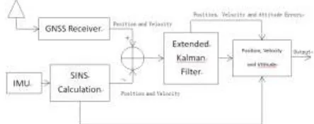
2.4 Position Velocity Loose Combination EKF Model
Loose combination is a simple SINS/GNSS combination application method. In this way, SINS and GNSS work independently, and the combination algorithm fuses the data and gives the optimal results, and finally feedback to the SINS. This combination method can provide better navigation results than GNSS or SINS alone.
Fig 1. The diagram of sins/gnss loose combination naviagtion.
a) State equation:
In this paper, the navigation parameter error is chosen as the filter state, and the estimated error is used to
correct the output of the SINS. The extended Calman filter state equation is as follows:
(6)
Where,
are the constant zero biases of the accelerometer and the gyroscope.
are respectively the random noise terms of the accelerometer and the gyroscope.
,
,
,
.
Measurement equation:
(7)
Where,
are respectively the position and velocity of the SINS solution in the navigation coordinate
system,
are respectively the position and velocity of the GNSS in the navigation coordinate system,
are respectively position random error and velocity measurement random error.
III.
EXPERIMENTAL VERIFICATION
In this paper, ADIS16334 chose as the IMU. Gyro input range , gyro bias , gyro
random walk , accelerometer measurement range , accelerometer bias . Positioning reference
station, ComNav T300 GNSS Receiver, real time dynamic RTK accuracy can reach 8mm. Positioning receiver, ComNav M600, dual frequency RTK accuracy of up to 10mm. Receiving antenna, ComNav AT300.
combination is higher.
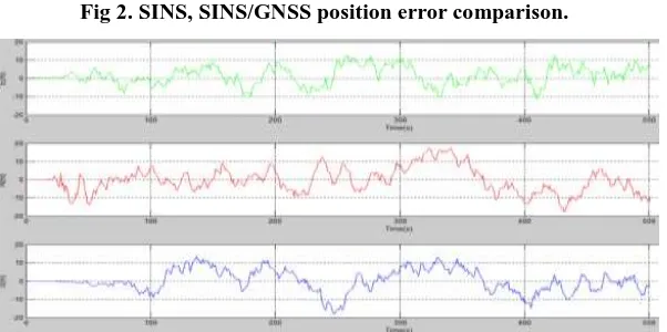
RESULTS
Fig 2. SINS, SINS/GNSS position error comparison.
Fig 3. SINS/GNSS position error.
IV.
CONCLUSIONS
On the basis of the process and the principle of the method of solving the strapdown inertial navigation system and the Extended Kalman Filter, this paper presents a method of SINS/GNSS position velocity loose combination navigation. In this paper, the error of navigation parameters as the filter state, the Extended Kalman Filter state equation and measurement equation are given. Through the field experiment in the farm machinery model car, the experimental results show that the SINS/GNSS position speed loose combination overcomes the problem of the rapid accumulation of navigation errors with time in the single SINS navigation, compared with the single SINS position and velocity measurement, the accuracy of the loose combination is higher. The feasibility of the proposed navigation method is verified in this paper.
REFERENCES
[1]. Su Xingjun, Liu Yongbo. Discussion on the Application of the GPS Satellite Positioning and Automatic
Navigation System of Agricultural Machinery[J].Agricultural Development and Equipments, 2014(6). ( in Chinese)
[2]. Hu Jingtao, Gao Lei, Bai Xiaoping, et al. Review of Research on Automatic Guidance of Agricultural
Vehicles[J]. Transaction of the Chinese Society of Agricultural Engineering,2015, 31(10):1-10.
[3]. Paul D G. Principles of GNSS, Inertial, and Multisensor Integrated Navigaion Systems[M]. 2nd
ed.BOSTON:Artech House,2013.
[4]. R. E. KALMAN. A New Approach to Linear Filtering and Prediction Problems[J]. Journal of Basic Engineering, 1960,82(1):35-45.
[5]. Buck T M, Wilmot J, Cook M J. Ahigh G, MEMS Based, Deeply Integrated, INS/GPS, Guidance,
Navigation and Control Flight Managemen Unit. In: Proceedings of IEEE/ION Position, Location, and Navigation Symposium, San Digeo, 2006:772-794.