Dynamics and Control on Double-drum Roller
Maximum Brake Deceleration
Hairong GU
Key Laboratory for Highway Construction Technology and Equipment of Ministry of Education, Chang’an University, Xi’an, China
e-mail: [email protected]
Yongqi WANG
Faculty of Transportation Engineering, Kunming University of Science and Technology, Kunming, China e-mail: [email protected]
Changming LI
Department of Petty Officer, Academy of Equipment Command and Technology, Beijing, China e-mail: [email protected]
Abstract—Reducing start and stop time without destroying
the pavement surface is important in enhancing productivity of double-drum roller and compact quality of asphalt pavement, but it is difficult in confirming the maximum brake deceleration or start acceleration of double-drum roller. Dynamic analysis is used in studying these questions, and a mathematic model of double-drum roller is established, based on the model, the factors which will affect the maximum brake deceleration of double-drum roller is studied, such as brake force from travel hydraulic travel system, the adhesive force from compacted ground, the inertia force of drums and double-drum roller itself. And the max brake deceleration equation is obtained which consider all these factors. It indicates that drum inertia affects the max brake deceleration of double-drum roller notable, and should be taken into account during design procedure and control program. At last a maximum deceleration control method based on slip control and classic PID algorithm is advised.
Index Terms—construction machine, double-drum roller,
travel system, brake deceleration, dynamics,
I. INTRODUCTION
Double-drum roller is one of the most important machines used in asphalt pavement construction, which mainly contributes in asphalt pavement compaction. As claimed in construction specifications issued in China, for the asphalt concrete temperature drops quickly after paved on the ground, double-drum roller should complete the asphalt compaction procedure as soon as possible during asphalt pavement constructing, ensure the asphalt compact temperature in limited range, and double-drum roller compacts the asphalt pavement usually 60~80m
one pass with restrictive velocity[1]. According the requirements, in all the compaction procedure, double-drum roller start and brake time is more than 20% of all [2], this affects the productivity of double-drum roller obviously, more double-drum rollers and cost is needed. Because the roller compact speed cannot change freedom, decreasing the start and brake time is most important in enhancing the productivity of double-drum roller and the compact quality of asphalt pavement, and maybe the only method.
Double-drum roller start and brake time is determined by the start acceleration and brake deceleration, which is mainly controlled by changing the travel hydraulic motors revolution, and influenced by the maximum force output from travel system and the maximum adhesive force supplying from ground [3]. More quickly start acceleration or brake deceleration of drums will result in the double-drum roller slipping (during the start deceleration procedure) or drums slipping (during the brake acceleration procedure), destroy the smooth pavement seriously.
Many literatures are published in describing the design, the control, the compact quality control, and the compact techniques on double-drum rollers, such as J.J Shen studies the parameters matching of hydraulic driving system of tandem vibratory roller[3], J.Y. Yin studies the closed hydraulic system and its application in the rollers [4], H.C. Wan studies the comment on three-step brake of road roller[5], N.B. Huang studies the method of calculation on travel hydraulic system pressure of double-drum roller[6], J Li studies the Anti-slip Control of Dual Hydraulic Drive Compactor[7], X.J. Zhang studies the Reverse-driving Control Method of Hydrostatic Tandem-Drum Vibratory Roller[8]. In all the literatures, no title on the start acceleration, the stop deceleration or the control methods is discussion, and only the research of H.C. Wan is close to the research here, but not the same.
(CHD2010JC062) Research of Central Colleges, Chang’an University (0901069C).Jiangsu Planned Projects for Postdoctoral Research Funds Corresponding author: Hairong Gu
other, only the brake dynamic procedure is studied in this paper, such as the components, the brake theory, the force analyses, the brake dynamic procedure, the maximum brake deceleration, the control method and the control algorithm of double-drum roller. Based on the research results, advice on brake deceleration control is put forward.
I. TRAVEL SYSTEM COMPOSITION AND USUAGE OF ROLLERS
A. Classification about roller
According to the structure and composition, Rollers mainly can be divided into single-drum roller, double-drum roller, tyre roller, and so on.
Single-drum roller travel system includes one drum and two tires, as shown in Fig.1.
Because the tires may destroy the surface during passing for the large GP (Ground Pressure) and tyre tracery, and cannot endure high temperature of asphalt concrete, single-drum roller is mainly used in earth compaction and other condition with no surface smooth requirements. There are many drum types, such as smooth drum, sheep-horn drum, impact drum, and so on.
Double-drum roller travel system has two identical smooth drums, as shown in Fig.2.
Double-drum roller is mainly used in asphalt compaction or other condition with strict surface smooth requirements.
Tyre roller travel system has multi-tyre, as shown in Fig.3.
Tyre roller can be used in all the conditions, but the weight is low.
Figure 3. Tyre roller
In the pavement surface compaction, especially the asphalt surface compaction, double-drum roller is the main compaction machine type, for the strict requirement on asphalt pavement surface. Design, control, work parameters adjust, and many other methods have be taken into account in improving double-drum roller compaction quality and the productivity.
B. Travel system Components of double-drum roller Double-drum roller composites of two drums, chassis, operator cabin, engine, hydraulic system, and so on. The two drums accounts for most machine weight, and acts as traction wheels. The surface of drum is smooth, which will not destroy the pavement surface. Usually in the drums(as shown in Fig.4), there are eccentric blocks making up of line jar, realizing vibrating compaction and getting larger GP, which has better effect than static compaction with the same weight.
Figure 1. Single‐drum roller
Because the structure other than travel system does not affect the brake deceleration, it is not discussed here. And the travel system is discussed detailed for its obvious affect.
Typical travel system used in double-drum roller is shown in Fig.5, which components of engine, hydraulic pump, flushing valve, flow divider valve, relief and topping valve, hydraulic motor, two drums, and many assemblies. Because the double-drum roller will change speed continuously, hydraulic travel system is the standard configuration for its infinitely variable speeds capability.
C. Brake theory of double-drum roller
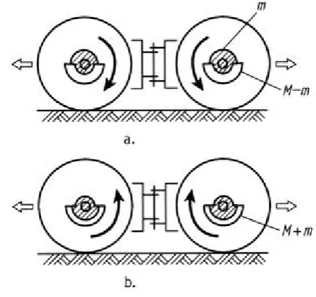
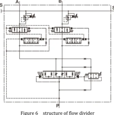
As shown in Fig.5, one pump and two motors make up of the closed circle hydraulic travel system, engine drives pump, pumps pressure oil to drive two motors in parallel, the motors drive two drums separately to travel forward or back by controlling the pump displacement and the pressure oil output direction, one flow divider valve (the structure is shown in Fig.6) is used in hydraulic system, ensures the two motors revolution at the same by controlling the pressure oil passing two motors at the same.
According to the work theory of hydraulic transmission, oil flows through the divider valve, the oil outputs from port A and port B is same, and the drums revolution is same, except for the turnaround condition, that additional oil will enter the port A or port B, determined by which will move more distance according
to turnaround theory. In this paper, only double-drum roller straight running condition is discussed, that both drums revolution is same all the time.
During running straight, if the pump control shaft of travel hydraulic system is backed to middle, pump displacement changes to zero, motors operates as pump, inverts output torque to drums, brake the rotating drums, and the braked drums interact with ground, ground adhesive force and resistance force supplies force in stopping the double drum roller until the double-drum roller is at a standstill.
Relief valve used here limits the maximum travel system pressure by relief additional oil, and then limit the maximum motors drive torque.
Figure 5 Travel system of double drum roller
D. Formulas on double-drum roller stop procedure The revolution of every motor is (when the pressure oil outputs from the port A and B is same, and drives two motors equally)
2
p gp m
gm
V V
ω
ω = (1)
Where
ω
p is travel pump revolution, the same as therevolution of engine
ω
e (rad/s); is displacement oftravel pump (ml/rad);
V
gm displacement of every travelmotor (ml/rad); m
gp
V
is
ω
is revolution of every travel motor (rad/s);The revolution of every drum is
m d
d
i ω
ω = (2)
Where is ratio of travel reducer, between the motor and drum;
d
i
d
ω
is revolution of drum (rad/s); The output torque of motor ism m gm
M =p V (3)
Where is output torque from every motor (Nm); is differential pressure of every motor (bar);
m
M
m
p
The output torque from every drum is
(4)
m d d i M
M =
Where
M
d is output torque from every drum(Nm); The output traction force from every drum is/
d m d
F =M r (5)
Figure 6 structure of flow divider
Where
F
d is traction force from every drum (N); is radius of drum (m);d
II. DYNAMICS MODEL OF BRAKE DOUBLE-DRUM ROLLER
A. Force analyses on double-drum roller brake procedure
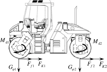
According to Newton's Laws of Mechanics, Force analysis on double-drum roller brake procedure is shown in Fig.7.
e analysis on double drum roller brake procedure
In Fig.7, , is brake torque on every drums from motors(Nm); , is adhesive gravity on every drum(N); , is friction force from ground(N);
, is traction force from ground(N). d1
M
1 fF
F
d2M
1 ϕG
2 f 2 ϕG
1 KF
F
K2Usually, the brake torque on drums, the adhesive force on drums, the friction force on drums, and the traction force on drums is same as each other as discussed at the before. d1 d2 1 2 1 2 1 K K
f f2
M
M
G
G
F
F
F
F
φ φ=
=
=
=
(6) So, some new expression symbols is import here forexplaining convenient, that
1 2
1 2
1 2
1 2
d d
K K K
f f f
d
M
M
M
G
G
G
F
F
F
F
F
F
φ φ φ
′ =
+
′ =
+
′ =
+
′ =
+
(7)Where
M
d′
is whole torque output from both drums (Nm);G
φ′
is whole adhesive weight on both drums, justthe same as the weight of double-roller drum (kg);
F
K′
is whole traction force on both drums (N);F
f′
is whole friction force on both drums (N).And
d d m gm
M′ =i p V (8)
(9)
G
φ′ =
mg
K
F
′
=
G
φ′
φ
(10)
f
F
′
=
G f
φ′
(11) Where is whole weight of double-drum roller (kg);
is acceleration of gravity (10m/s2);
m
g
φ
is groundadhesive coefficient;
f
is ground friction coefficient.B. Double-drum roller brake dynamics analyses
According to dynamics theory, every drum deceleration determined by force is
(
)
2
d K f
d
d d
M
F
F
r
d
dt
J
ω
= −
′
−
′
+
′
(12)
Where
J
d is inertia of every drum (kgm2).When the revolution of engine is certain, the volume coefficient loss of pump, motors, and whole hydraulic system is ignored, the revolution of drum is
2 gp p d gm d V V i ω
ω = (13)
If the aim deceleration of drum is certain, Pump displacement change speed corresponding to drum revolution change is
2
gp gm d d p
dV V i d
dt dt
ω ω
= (14)
Correlated (14) with (11)
(
)
(
d K f d)
gp gm dp d
M F F r
dV V i
dt ω J
′− ′+ ′
= − (15)
III. BRAKE FORCE INFLUENCING FROM GROUND ADHERING FACTOR
According the closed-circle hydraulic system work theory, when the pump displacement changes to zero, the
rt and input port of motors is exchanged, and motors in the circle operates as a pump, stops the external movement assemble, just like the brake.
output po
Double-drum roller brake is achieved by changing the pump displacement to zero, and utilizing the motor operation as a pump adding resistance on drum, stopping the drum. But the force stopping the double-drum roller is limited by the ground adhering force and the resistance force, and double-drum roller brake deceleration is determined by the ground adhesive force and the resistance force
So the obtained brake deceleration of double-drum roller is
1 ϕ
G
F
f1F
K1 d1M
2 ϕ
G
F
f2F
K2d2
M
(
F
KF
f)
dv
dt
m
′
+
′
= −
(16)d d
d
dv
r
dt
dt
ω
′
=
(17)Where is velocity of double-drum roller (m/s);
v
ω
d′
is revolution of drum corresponding to the velocity of double drum roller (rad/s).
Pump displacement change speed corresponding to the double-drum roller is
2
gp gm d d p
dV
V i d
dt
dt
ω
ω
′
′
=
(18)or
(
)
2
2
K f dgp gm d
p d
F
F
r
dV
V i
dt
ω
mr
′
+
′
′
= −
(19)
Where is pump displacement corresponding to the double-drum roller velocity (ml/rad).
gp
V
′
When
(
F
K′
+
F
f′
)
reaches the maximum that(
)
maxK f K f
F
′
+
F
′
=
F
′
+
F
′
(20)And
(21)
(
F
K′
+
F
f′
)
max=
G
φ′
(
φ
+
f
)
Where
φ
is ground adhesive coefficient.And the maximum deceleration double-drum roller can achieve at this special condition is.
(
max
dv
g
f
dt
= −
φ
+
)
(22)It is obviously that the maximum deceleration of double-drum roller is closely related to the ground adhesive coefficient. When ground condition changes, as shown in Tab.1, the maximum deceleration of roller is diverse. Along the compacting procedure, ground dense increasing, ground adhesive force changing. In general, adhesive force is less at the beginning for the loose materials, the maximum deceleration of roller is less with no slipping; adhere force is bigger at the ending for the tight materials; the maximum deceleration of roller is bigger with no slipping.
TABLE I. RESISTANCE AND ADHERING RATIO OF WHEEL VEHICLE
ground factor resistance ratio ƒ adhering ratio φ
asphalt pavement 0.02~0.03 0.7~0.9
plowed field 0.12~0.18 0.5~0.7
wetland 0.22~0.25 0.1~0.2
Pump displacement change speed corresponding to roller maximum deceleration determined by the ground adhere force is
max max
2
gp gm d d
e
dV
V i d
dt
dt
ω
ω
′
′
=
(23)(
max)
2 max
2
K f dgp gm d
e d
F
F
r
dV
V i
dt
ω
mr
′
+
′
′
= −
(24)If the drive force of hydraulic system is enough and the pump displacement change speed exceeds the value described in (24), drum revolution is lower than equivalent revolution of drum roller; the double-drum roller will slip on the pavement surface, and destroy the smooth pavement surface.
IV.ROLLER TRAVEL SYSTEM TORQUE SETTING TO MEET THE MAXIMUM DECELERATION
According to the brake dynamics model, the maximum deceleration of double-drum roller is
(
)
max
max
2
( )
gp gm d d
e
d K f d
gm d
e d
dV V i d
dt dt
M F F r
V i J ω ω ω ′ = ′ ′ − + = − (25)
To meet the requirement, that
(
max max)
max 2
(
)
(
)
d K f
d
K f d
d
d
M
F
F r
J
F
F r
mr
′
′
−
+
′
+
′
≥
(26) And(
2)
max
max 2
(
K f)
d d dd
d
F
F r
J
mr
M
mr
′
+
′
+
≥
max max max2
d m d
m gm d
Where
M
M
i
p
V i
=
=
max mp
(
)
Where is relief valve setting pressure of double-drum roller travel hydraulic system (bar).
When
2 max
max 2
(
K f)
d d dd
d
F
F r
J
mr
M
mr
′
+
′
+
<
(
max2)
maxgp gm d d
p d d
dV V i M
dt ω J mr
′ = −
+ (27)
For usual wheel vehicle, the material density is little, the weight of wheel is low, and the inertia of tire can be ignored relative to the whole vehicle inertia, the maximum output torque of travel hydraulic system can be set according to ground adhesive force.
But for double-drum roller, the material components of drums is big, and the weight of drums accounts most of the double-drum roller, the inertia of drum cannot be ignored relative to the whole inertia, and the maximum output torque of travel hydraulic system should be larger to meet the maximum brake torque requirement.
V.SLIP RATIO CONTROL ON DOUBLE-DRUM ROLLER
For the adhesive coefficient is changing during the compaction procedure, double-drum roller design cannot deal with the change affect on double-drum roller maximum deceleration. And adjusting the maximum deceleration according the surface character needs detailed data on the ground adhesive coefficient and its change rules, which is difficult to reach even with much money.
Control method based on some observable parameters maybe a good way in dealing with these questions, such as slip ratio.
Double-drum roller destroys the pavement surface, just because the slip of machine (during brake deceleration) or drums (during start acceleration), controlling the slip ratio under a low level can avoid double-drum roller destroying the pavement surface with the lest brake time and start time, which can be realized by measuring the double-drum roller slip ratio and controlling the pump displacement changing speed.
A. Slip measure on double-drum roller
During the brake deceleration procedure of double-drum roller, double-drum revolution is lower than that of machine velocity equivalent revolution. During the start acceleration procedure of double-drum roller, drum revolution is higher than machine velocity equivalent revolution. So in different procedure, slip ratio is calculated in different way.
During brake deceleration procedure of double-drum roller, slip ratio is
d d
d
ω ω δ
ω
′ −
= (28)
Where
ω
d′
is equivalent revolution of double-drum roller velocity (rad/s)./
d v rd
ω′ = (29)
Where
v
is velocity of double-drum roller (m/s). Revolution of drums can be measured with proximity switch and code wheel installed near drum axle, as shown in Fig.7. When the drum turn around, rectangle pulse single output from the proximity switch, the controllerires the rectangle single, calculates the period, and the drum revolution at last.
acqu gets
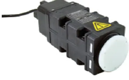
Velocity of double-drum roller can be measured with radar speed indicator, one type of noncontact velocity sensor, as shown in Fig.8. Because there is no simple way measure the machine velocity with contacted sensor, noncontact sensors are used. This sensor is installed on double-drum roller, points at the ground. Following the run of double-drum roller, rectangle pulse signal which is proportion to the velocity of machine is output; controller acquires the signal, calculates the period, and gets the double-drum roller velocity at last.
Figure 8 revolution measurement with proximity switch
With the get drum revolution and double-drum roller velocity, according to (28), (29), the slip ratio can be obtained.
Figure 9 radar speed indicator
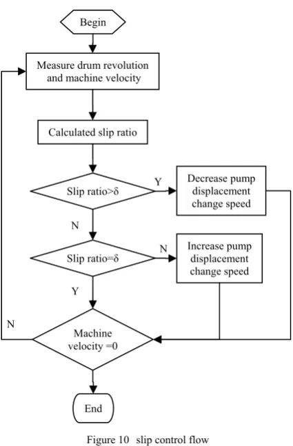
B. Slip ratio control
A control flow is added into the double-drum roller control program, as shown in Fig.9.
And control signal is produced based on classics PID algorithm, controls the pump displacement, limits the slip ratio, as shown in Fig.10.
If the object slip ratio is set to zero, and the object deceleration is set to maximum, with the PID controller, the double-drum roller stops quilkly without destroying the pavement surface.
During start, if the object slip ratio is set to zero, and the object acceleratio is set to maximum, with the PID controller, the double-drum roller starts quilkly without destroy the pavement surface.
VI.SUMMARY
In this paper, double-drum roller brake dynamics model is established, as described in the dynamics model, the ground adhering force and the maximum output torque of travel hydraulic system is important in determining the maximum deceleration of double-drum
roller. When the output torque of travel hydraulic system is enough, the maximum deceleration of roller is mainly determined by the ground adhesive ratio. And the inertia of drum is large, which cannot be ignored during the design of the maximum output torque of double-drum roller travel hydraulic system, when the maximum deceleration of double drum roller is wanted. More experiments data should be collected to determine different ground adhesive ratio and different maximum brake deceleration. And control method maybe one good method in deal with maximum deceleration changing along the compaction procedure.
ACKNOWLEDGMENT
The project was supported by the Special Fund for Basic Scientific Research of Central Colleges, Chang’an University (CHD2010JC062) and Jiangsu Planned Projects for Postdoctoral Research Funds (0901069C).The authors wish to thank for the help from Key Laboratory for Highway Construction Technology and Equipment of Ministry of Education, the engineering equipments and technology research center of the Education Ministry in Chang’an University, which give these paper funding and technical support.
REFERENCES
[1] JTG F40-2004.Technical Specifications for Construction of Highway Asphalt Pavement.
[2] Z.W. Sun, X.L. Wei, and Q. Wang,. “The Dynamic Process of Oscillatory Compaction and Its Response Characteristic”, China Journal of Highway and Transport, vol.11, Nov.1998, pp. 117-126
[3] J.J. Shen, Z.X. Feng, and J.R. Hou, “Parameters Matching of Hydraulic Driving System of Tandem Vibratory Roller”, Journal of Chang’an University: Natural Science edition, vol.25, May 2009, pp:122-126
[4] J.Y. Yin, “Closed Hydraulic System and Its Application in the Rollers”, Construction Machine Technology & Management, vol.23, Feb. 2010, pp:88-92
[5] H.C. Wan, “Comment on Three-step Brake of Road Roller”, Construction Mechanization, vol.28, June 2007, pp:23-27
[6] N.B. Huang.” How to Calculate Travel System Pressure of the Tandem Roller”, Construction Machine Technology & Management, vol.23, Jun. 2010, pp:133-135
[7] J. Li. “Anti-slip Control of Dual Hydraulic Drive Compactor”. Construction Machinery and Equipment, vol.38, Apr 2007, pp:12-15
[8] X.J. Zhang.” Study on the Reverse-driving Control Method of Hydrostatic Tandem-Drum Vibratory Roller”, Xi’an: Chang’an University, 2010.
Hairong GU (Jiangsu, China, 1981-08-13). Doctor of engineer, Mechanical Design and Theory, Chang’an University, Xi’an, China, 2008. Major research field is mechanotronics on construction machine.
He is a lecturer of Chang’an University; the main research projects are on construction machinery design, Begin
Measure drum revolution and machine velocity
Calculated slip ratio
Slip ratio>δ
Decrease pump displacement
Set Slip Ratio
PID Controller
Pump Displacement
Drum Machine Hydraulic
System
Drum
Revolution MachineVelocity Slip
Ratio
change speed
Slip ratio=δ
Increase pump displacement change speed
End Machine velocity =0
Y
N
N
N
Y
Figure 10 slip control flow
control, and optimize, especially on hydraulic transmission and control.
Changming LI (Shanxi, China, 1979-06-11). Master of Mechanical Engineering, Xi'an Jiaotong University, Xi’an, China, 2005. The major research field is mechanotronics on vehicles and construction machine.
Yongqi WANG (Yunnan, China,1969-06-13), Doctor of engineer, Mechanical Design and Theory, Chang’an University, Xi’an, China, 2008. Major field of study is mechanotronics on construction machine.
He is a lecturer at Kunming University of Science and Technology, the main research projects are on construction machinery design, control, and optimize.