Implementation of Error Correction Technique
using OCC on FPGA
Vijendra P. Meshram Neha R. Tawade
Assistant professor UG Student
Department of Electronics Engineering Department of Electronics Engineering Dr. Babasaheb Ambedkar College Of Engineering & Dr. Babasaheb Ambedkar College Of Engineering &
Research Research
Sanjana M. Deshmukh Sameer V. Nandanwar
UG Student UG Student
Department of Electronics Engineering Department of Electronics Engineering Dr. Babasaheb Ambedkar College Of Engineering & Dr. Babasaheb Ambedkar College Of Engineering &
Research Research
Dipika D. Borkar UG Student
Department of Electronics Engineering
Dr. Babasaheb Ambedkar College Of Engineering & Research
Abstract
When data is transmitted through a channel (wired or wireless), some noises may affect the reliability of data. Because of this actual information get changed. This referred as error. Therefore error detection and correction techniques are required at the receiver. Orthogonal code is one of the coding techniques which detect as well as correct the corrupted data. In this method each k-bit data set is converted into n-bit orthogonal code. An n-bit orthogonal code contains n/2 1’s and n/2 0’s, that means parity of this code is always zero. In this paper we present a new methodology to enhance the error correction capability of orthogonal code. This technique is implemented using VHDL and field programmable gate array (FPGA).
Keywords: Orthogonal code, Antipodal code, Error correction and detection, FPGA
________________________________________________________________________________________________________
I. INTRODUCTION
Data transmission from one device to another with acceptable accuracy is the basic need for every communication system. But during data transmission error may generate due to interference. Error generation may be in terms of change in the bit. In single bit error a 0 is change to 1 or 1 is change to 0 and in case of multiple errors several bits are change. Some of the error detection techniques like cyclic redundancy check can only detect error whereas some are designed to detect as well as correct the errors such as salomon codes. However the existing techniques are not capable of achieving high efficiency and to meet bandwidth requirements, especially with increase in the quantity of data to be transmitted. Orthogonal cod is one of the code that can overcome the drawbacks in the existing techniques and detect as well as correct the corrupted data more efficiently.
II. ORTHOGONAL CODE
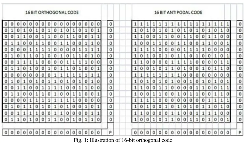
Fig. 1: Illustration of 16-bit orthogonal code
Since there is an equal number of 1’s and 0’s, each orthogonal code will generate a zero parity bit. Therefore, each antipodal code generatea zero parity bit. A main advantage of this method is that the transmitter does not have to send the parity bit since the parity bit is always zero. Therefore, if there is an error in the transmitted data the receiver will be able to detect it by generating the parity bit at the receiver.
Before transmission a k-bit data set is transformed into a unique n-bit code. For example, a 5-bit data set is represented by a unique 16-bit orthogonal code which is transmitted without parity bit. When received, the data is decoded based on code corelation.it can be done by setting a threshold midway between two orthogonal codes.This is given by the following equation-
dth = n/4 (1)
Where n is the code length and dth is the threshold, which is midway between two orthogonal codes.Therefore, for 16-bit orthogonal code, we have, 𝑑𝑡ℎ = 16/4 = 4.
Orthogonality of each generated code is checked by finding the cross correlation with the previously generated codes. If the correlation is zero then only code is accepted otherwise repeat request is generated. This correlation process is governed by following equation, where a pair of n-bit codes X1, X2.... Xn and Y1, Y2...Yn are compared to produce,
R(x, y) = ∑ Xi . Yi <n
4− 1 n
i=1 (2)
R(x, y) is correlation function. n/4 is the threshold value between two orthogonal codes as shown in equation (1). The average number of errors that can be corrected by using this process can be determined by combining (1) and (2), giving,
t = n − R(x, y) = n
4− 1 (3)
Where t is the number of errors that can be corrected by means of an n-bit orthogonal code. For example, a single error correcting orthogonal code can be constructed by means of an 8-bit orthogonal code (n = 8). Similarly, a three error correcting orthogonal code can be constructed by means of a16-bit orthogonal code (n = 16), and so on. Table-2 below shows a few orthogonal codes and the corresponding error correcting capabilities.
Table - 1
Orthogonal codes and corresponding error correction capabilities. Code length (n) Correction capability (t )
8 1
16 3
32 7
64 15
III. DESIGN METHODOLOGY
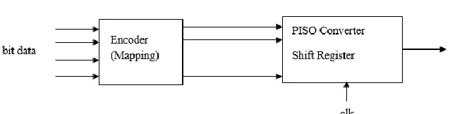
Transmitter:
Transmitter contains encoder, orthogonal check and parallel to serial converter. Encoder encodes incoming k-bit data set into equivalent n-bit orthogonal code, where n=2k-1. For example, 4-bit data is encoded into 8-bit (24−1) orthogonal code. Every newly
generated code is then compared with previously generated code for checking the orthogonally. If their auto correlation satisfies eq. (1) then it is a valid orthogonal code otherwise it will be rejected. This generated code is then transmitted serially with the help of parallel to serial converter.
Fig. 2: Block diagram of transmitter section
Receiver:
The received serial bits are converted into n-bit parallel code by serial to parallel converter. The numbers of 1’s in this parallel code are then count. If “count” is equal to n/2 then it is correct orthogonal code without error and if it is not equal to n/2 then it is considered as corrupted code. Number of corrupted bits is calculated by “count ± (n/2)”. In error correction block this n-bit parallel code is compared with all the codes in the lookup table. This is done by counting the number of ones in the signal resulting from XOR operation between the received code and each combination of the orthogonal codes in the lookup table. A counter is used to count the number of 1’s after XOR operation. It also searches for the minimum count. The orthogonal code in the lookup table which is associated with the minimum count is the closest match for the corrupted received code. The matched orthogonal code in the lookup table is the corrected code, which is then decoded to k-bit data. Associated with more than one combination of orthogonal code then a signal, REQ goes high.
Fig. 3: Block diagram of receiver section
IV. IMPLEMENTATION
A Spartan-6 hardware board and ISE Xillinx 13.2 software have been used for code testing.
Transmitter
Fig. 5 shows an example of the results of the transmitter simulation corresponding to the input data value "11011" labelled as ‘data’. This data has been encoded to the associated orthogonal code “1001100101100110” labelled ‘ortho’. The signal ‘EN’ is used to enable the transmission of the serial bits ‘txcode’of the orthogonal code with every rising edge of the clock.
Receiver:
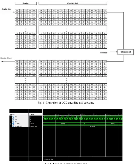
Upon reception, the incoming serial data is converted into 16-bit parallel code „rxcode‟. Counter is used to count the number of 1st after XOR operation between the received code and all combinations of orthogonal code in the lookup table. Fig.6, the received code is rxcode=“0110011001100110”, count=‟0‟ and hence the received code is not corrupted. The code is then decoded to the corresponding final data 00010.
The results of the simulation show that for a k-bit data, the corresponding n-bit orthogonal code is able to detect any faulty combination other than the combinations of orthogonal code in the lookup table.
Fig. 5: Illustration of OCC encoding and decoding
Fig. 6: Simulation results of Receiver
V. CONCLUSION
detection up to 99.9% for 16-bit coding. It is noted that with this method, the transmitter does not have to send the parity bit since the parity bit is known to be always zero. Therefore, if there is a transmission error, the receiver will be able to detect it by generating a parity bit at the receiver end.
REFERENCES
[1] N. Kaabouch, A. Dhirde, and S. Faruque, “Improvement of the Orthogonal Code Convolution Capabilities using FPGA Implementation”, IEEE Electro /
Information Technology Proceedings. Pp. 380-384, 2007.
[2] S. Faruque, N. Kaabouch, and A. Dhirde, “Forward error control coding based on orthogonal code and its implementation using FPGA ” Wireless and
Optical Communication Proceedings, PP 565-630, ACTA Press, June 2007.
[3] U. K. Kumar, and B. S. Umashankar, “Improved hamming code for error detection and correction”, 2007 2nd International Symposium on Wireless
Pervasive Computing, pp. 498-500.
[4] Z. Cai, J. Hao, S. Sun, and F. P. Chin, “A high-speed reed-solomon decoder for correction of both errors and erasures”, 2006 IEEE International
Symposium on Circuits and Systems, pp. 281-284.
[5] S. Faruque, “Error Control Coding based on Orthogonal Codes”, Wireless Proceedings, Vol. 2, pp. 608-615, 2004.
[6] S. Shukla, N.W. Bergmann, “Single bit error correction implementation in CRC-16 on FPGA”, in Conf. Rec. 2004 IEEE Int. Conf. on Field-Programmable
Technology, pp. 319-322.
[7] T. Baicheva, S. Dodunekov, and P. Kazakov, “Undetected error probability performance of cyclic redundancy-check codes of 16-bit redundancy”, IEEE
Proceedings. Communications, Vol. 147, No. 5, pp. 253-256, Oct. 2000.
[8] A. Hokanin, H. Delic, and S. Sarin, “Two dimensional CRC for efficient transmission of ATM Cells over CDMA”, IEEE Communications Letters, Vol. 4,
No. 4, pp. 131-133, April 2000.
[9] V. Stylianakis, S. Toptchiyski, “A Reed - Solomon coding/decoding structure for an ADS modem”, in Conf. Rec. 1999 IEEE Int. Conf. on Electronics,