17
INTRODUCTION TO FACTS CONTROLLERS
A CRITICAL REVIEW
BINDESHWAR SINGH1, K.S. VERMA1, DEEPENDRA SINGH1 , C.N. SINGH2, ARCHNA SINGH2, EKTA AGRAWAL3, RAHUL DIXIT1, BALJIV TYAGI4
1Kamla Nehru Institute of Technology (KNIT), Sultanpur-228118, U.P., India
2HBTI, Kanpur, U.P., India
3BIET Jhansi, U.P., India
4Indian Institute of Technology, Roorkee, Uttarakhand, India
Email: [email protected], [email protected]
ABSTRACT
This paper presents the introduction of various FACTS controllers such as SVC, TCSC, TCPAR or TCPAT, SSSC, STATCOM, UPFC, IPFC, GUPFC, HPFC for operation, control, planning & protection from different performance point of view such as increased the loadability, improve the voltage profile, minimize the active power losses, increased the available transfer capacity, enhance the transient and steady-state stability, and flexible operations of power systems. Also this paper presents the current status on the introduction of various FACTS controllers such as SVC, TCSC, TCPAR or TCPAT , SSSC, STATCOM, UPFC, IPFC, GUPFC, HPFC for operation, control, planning & protection from different performance point of view such as increased the loadability, improve the voltage profile, minimize the active power losses, increased the available transfer capacity, enhance the transient and steady-state stability, and flexible operations of power systems. Authors strongly believe that this article will be very much useful to the researchers for finding out the relevant references in the field of the various FACTS controllers for operation, control, planning & protection of power systems.
Keywords:-Flexible AC Transmission Systems (FACTS), FACTS Controllers, SVC, TCSC, TCPAR or TCPAT, SSSC, STATCOM, UPFC, IPFC, GUPFC, HPFC, Power Systems.
1. INTRODUCTION
The power flow over a transmission line depends mainly on three important parameters, namely
voltage magnitude of the buses (
V
), impedance ofthe transmission line (
Z
) and phase angle betweenbuses (
θ
). The FACTS devices control one ormore of the parameters to improve system performance by using placement and coordination of multiple FACTS controllers in large-scale emerging power system networks to also show that the achieve significant improvements in operating parameters of the power systems such as small signal stability, transient stability, damping of power system oscillations, security of the power system, less active power loss, voltage profile, congestion management, quality of the power system, efficiency of power system operations, power transfer capability through the lines, dynamic performances of power systems, and the
loadability of the power system network also increased. As FACTS devices are fabricated using solid state controllers, their response is fast and accurate. Thus these devices can be utilized to improve the voltage profile of the system by using coordinated control of FACTS controllers in multi-machine power systems in this work.
A. Generation of FACTS Controllers:
The following generation of FACTS controllers for the development of FACTS controllers:
a. First Generation of FACTS Controllers:
The following FACTS controllers such as Staic
18 developed in the first generation of FACTS controllers.
b. Second Generation of FACTS Controllers:
The following FACTS controllers such as Static
Synchronous Compensator (STATCOM), Static Synchronous Series Compensator (SSSC), Unified Power Flow Controller (UPFC), and Interline Power Flow Controller (IPFC) are developed in the second generation of FACTS controllers.
B. Concepts of FACTS Technology:
IEEE definition of FACTS and FACTS controllers are given as [1].
• Flexible AC Transmission System (FACTS): Alternating current transmission systems incorporating power electronics based and other static controllers to enhance controllability and increase power transfer capability.
• FACTS Controller: Power electronics based system and other static equipment that provides control of one or more AC transmission system parameters.
In general, FACTS controllers can be divided in following categories
Series controllers such as
Thyristor Controlled Series Capacitor (TCSC), Thyristor Controlled Phase Angle Regulators (TCPAR or TCPST), and Static Synchronous Series Compensator (SSSC)
Shunt controllers such as Staic
Var Compensator (SVC), and Static Synchronous Compensator (STATCOM)
Combined series-series
controllers such as Interline Power Flow Controller(IPFC)
Combined series-shunt
controllers such as Unified Power Flow Controller(UPFC)
In this thesis we shall concentrate only on the TCSC, SVC, STATCOM, and UPFC devices. A brief review of series, shunt, series-series, and series-shunt devices such as TCSC, TCPAR or TCPST, SSSC, SVC, STATCOM, IPFC, and UPFC, GUPFC, HPFC are presented in below.
This paper is organized as follows: Section II discusses the introduction to various FACTS controllers. Section III presents the results and discussion of the problem. Section IV presents the conclusions of the paper.
2. INTRODUCTION TO VARIOUS FACTS CONTROLLERS
A. Thyristor Controlled Series Capacitor (TCSC) [1]-[18]
A TCSC is a capacitive reactance compensator, which consists of a series capacitor bank shunted by a thyristor controlled reactor in order to provide a smoothly variable series capacitive reactance [1].
Even through a TCSC in the normal operating range in mainly capacitive, but it can also be used in an inductive mode. The power flow over a transmission line can be increased by controlled series compensation with minimum risk of sub-synchronous resonance (SSR) [1]. TCSC is a second generation FACTS controller, which controls the impedance of the line in which it is connected by varying the firing angle of the thyristors. A TCSC module comprises a series fixed capacitor that is connected in parallel to a thyristor controlled reactor (TCR) i. e. Shown in Fig.1. A TCR includes a pair of anti-parallel thyristors that are connected in series with an inductor. In a TCSC, a metal oxide varistor (MOV) along with a bypass breaker is connected in parallel to the fixed capacitor for overvoltage protection. A complete compensation system may be made up of several of these modules.
α
α
19 The steady-state impedance of the TCSC is that of a parallel LC circuit, consisting of fixed capacitive
impedance, XC, and a variable inductive
impedance, XL(α), that is,
C L
L C TCSC
X X
X X X
− =
) (
) ( )
(
α α α
(1)
Where
∞ ≤ ≤
− −
= , ( )
2 sin 2 )
( α
α α
π π
α L L L
L X X X
X
(2)
L
XL =ω , and α is the delay angle measured from
the crest of the capacitor voltage (or, equivalently, the zero crossing of the line current). The impedance of the TCSC by delay is shown in Fig. 2.
The TCSC has three basic modes of operation
Thyristor valve bypass mode (inductive region operation:
0
≤ ≤
α α
Llim) Thyristor valve blocked mode (resonance region for inhibited operation:
lim lim
L C
α
≤ ≤
α α
) Vernier control mode (capacitive region operation:
α
Clim≤ ≤
α π
/ 2
)1. Thyristor valve bypass mode (inductive region operation:
0
≤ ≤
α α
Llim): In the bypass modethyristors are gated for full conduction and the current flow in the reactor is continuous and sinusoidal. In this case the net reactance is slightly inductive because the susceptance of reactor is larger than that of the capacitor. This mode is mainly used for protecting the capacitor against the overvoltage (during transient overcurrents in the line). In this mode of operation the behaviour of reactance of TCSC module as follows.
2. Thyristor valve blocked mode (resonance region for inhibited operation:
α
Llim≤ ≤
α α
Clim): Inthe inserted mode with thyristor blocked, no current flows through the valve as the gate pulses are suppressed. In this mode, the TCSC reactance is the same as that the fixed capacitor. This mode is also termed as waiting mode. This mode is used to provide control and protective measures. The breaker is generally provided to remove TCSC from service when there are internal TCSC
failures. In this mode of operation the behaviour of reactance of TCSC module as follows.
3. Vernier control mode (capacitive region operation:
α
Clim≤ ≤
α π
/ 2
): In vernier controlmode, thyristors are gated in such a manner that a controlled amount of inductive current can be circulate through the capacitor thereby increasing effective capacitive/inductive reactance of the module. In this mode of operation the behaviour of reactance of TCSC module as follows.
All the modes of operation (regions of operation) of TCSC are shown in Fig.2.2.
Fig.2. TCSC equivalent Reactance as a function of firing angle
4. Explanations of above TCSC characteristics:
The TCSC thus presents a tunable parallel LC circuit to the line current that is substantially a constant alternating current source. As the
impedance of the controlled reactor,
X
L( )
α
, isvaried from its maximum (infinity) towards its
minimum
(
ω
L
)
, the TCSC increases its minimumcapacitive impedance,
X
TCSCmin=
X
C=
1/
ω
C
,
( and thereby the degree of series capacitive compensation) until parallel resonance at
( )
C L
X
=
X
α
is established andX
TCSCmaxtheoretically becomes infinite. Decreasing
X
L( )
α
further, the impedance of the TCSC,
X
TCSC( )
α
becomes inductive, reaching its minimum value of
( ) /
( )
C L L C
X X
α
X
α
−
X
atα
=
0
, where thecapacitor is in effect bypassed by the TCR. Therefore, with the usual TCSC arrangement in
which the impedance of the TCR reactor,
X
L,issmaller than that of the capacitor,
X
C, the TCSChas two operating ranges around its internal circuit
20
where
X
TCSC( )
α
is becomes capacitive, and theother is the
0
≤ ≤
α α
Llimrange, where( )
TCSCX
α
is inductive, as illustrated in figure .2.From above characteristics it is observed that TCSC can’t work in a particular band of firing angle i.e. shown in above figure due to resonance phenomena occurs in TCSC in this zone. This is the drawback of TCSC operations in power systems.
5. Installation of TCSC device: Initial experience
with TCSC installation has been favourable. A TCSC has been installed on the American Electric Power (AEP) 345 kV system in 1991 and another on the Western Area Power Administration (WAPA) 230 kV system in northeastern Arizona at the Kayenta substation in 1992. A third TCSC has been connected to the BPA 500 kV system at Slatt in 1993 for power flow control and improvement of system performance.
B. Thyristor Controlled Phase Angle Regulators (TCPAR) [19]
The TCPAR is equipment that can control power flow in transmission lines of power system by regulating the phase angle of the bus voltage. Environment restrictions usually restrict opportunities of reinforcement through the consideration of new routes. In
such a situation, Flexible AC Transmission System (FACTS) controllers such as TCPAR play an important role in increasing loadability of the existing system and controlling the congestion in the network.
FACTS device like TCPAR can be used to regulate the power flow in the tie-lines of interconnected power system. When TCPAR is equipped with power regulator and frequency based stabiliser it can also significantly influence the power flow in the transient states occurring after power disturbances. In the case of simple interconnected power system, consisting of two power systems the control of TCPAR can force a good damping of both power swings and oscillations of local frequency. In the case of larger interconnected power system consisting of more than two power systems the influence of the control of TCPAR on damping can be more complicated. Strong damping of local frequency oscillations and power swings in one tie-line may cause larger oscillations in remote tie-lines and other systems. Hence using devices like TCPAR as a tool for damping of power swings
and frequency oscillations in a large interconnected power system must be justified by detailed analysis
of power system dynamics.
The power injection model of TCPAR is shown in Fig.3.
Fig. 3.Power injection model of TCPAR
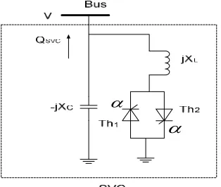
C. Static Var Compensator (SVC) [20]-[44]
According to IEEE-CIGRE co-definition [1], a static var compensator is a static var generator whose output is varied so as to maintain or control specific parameters (e.g. voltage or reactive power of bus) of the electric power system.
21 signals such as line active power, line reactive power, line current, and computed internal frequency.
Static VAR Compensator (SVC) is a shunt connected FACTS controller whose main functionality is to regulate the voltage at a given bus by controlling its equivalent reactance. Basically it consists of a fixed capacitor (FC) and a thyristor controlled reactor (TCR). Generally they are two configurations of the SVC i.e. shown in Fig. 4.(a)&(b)
1. SVC total susceptance model: A changing
susceptance Bsvc represents the fundamental
frequency equivalent susceptance of all shunt modules making up the SVC as shown in Fig. 4.(a).
2. SVC firing angle model: The equivalent
reactance XSVC, which is function of a changing
firing angle α, is made up of the parallel
combination of a thyristor controlled reactor (TCR) equivalent admittance and a fixed capacitive reactance as shown in Fig. 4. (b).
This model provides information on the SVC firing angle required to achieve a given level of compensation.
α
α
Fig. 4. (a) SVC firing angle model
α
Fig. 4. (b) SVC total susceptance model
Figure 5 shows the steady-state and dynamic voltage-current characteristics of the SVC. In the
active control range, current/susceptance and reactive power is varied to regulate voltage according to a slope (droop) characteristic. The slope value depends on the desired voltage regulation, the desired sharing of reactive power production between various sources, and other needs of the system. The slope is typically1-5%. At the capacitive limit, the SVC becomes a shunt capacitor. At the inductive limit, the SVC becomes a shunt reactor (the current or reactive power may also be limited).
min
I
set
I
I
maxmax
B
min
B
Fig.5. steady-state and dynamic voltage/current Characteristics of the SVC
SVC firing angle model is implemented in this paper. Thus, the model can be developed with respect to a sinusoidal voltage, differential and algebraic equations can be written as
k SVC
SVC jB V
I =− (3)
The fundamental frequency TCR equivalent
reactance XTCR
σ σ
π sin − = L TCR
X X
(4)
Where σ =2(π−α),XL =ωL
And in terms of firing angle
α α
π π
2 sin ) ( 2 − +
= L
TCR
X X
(5)
σ and αare conduction and firing angles
respectively.
At α =900, TCR conducts fully and the equivalent
22
XTCR becomes XL, while atα=1800, TCR is
blocked and its equivalent reactance becomes infinite.
The SVC effective reactance XSVC is determined
by the parallel combination of XC and XTCR
L C
L C SVC
X X
X X X
π α α
π π α
− +
− =
] 2 sin ) ( 2 [ ) (
(6)
Where XC = 1ωC
⎭ ⎬ ⎫ ⎩
⎨
⎧ − + −
=
L C C k k
X X X V Q
π
α α
π ) sin2 (
2 [
2
(7)
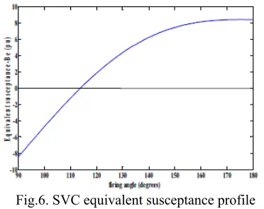
The SVC equivalent reactance is given above equation. It is shown in Fig. that the SVC
equivalent susceptanc (BSVC =−1/XSVC)
profile, as function of firing angle, does not present
discontinuities, i.e., BSVC varies in a continuous,
smooth fashion in both operative regions. Hence, linearization of the SVC power flow equations,
based on BSVCwith respect to firing angle, will
exhibit a better numerical behavior than the
linearized model based onXSVC . In SVC, the
resonance phenomenon is present as similar to TCSC. So, this device cant operated in a particular zone due these phenomena. This is the drawback of SVC operations in power systems. Figure 6. Shows the SVC equivalent susceptance profile.
Fig.6. SVC equivalent susceptance profile
D. Static Synchronous Series Compensator (SSSC) [45]-[48]
A SSSC is a static synchronous generator operated without an external electric energy source as a series compensator whose output voltage is in quadrature with, and controllable independently of the line current for the purpose of increasing or decreasing the overall reactive voltage drop across
the line and thereby controlling the transmitted electric power. The SSSC may include transiently rated energy source or energy absorbing device to enhance the dynamic behaviour of the power system by additional temporary real power compensation, to increase or decrease momentarily, the overall real voltage drop across the line [1].
An SSSC incorporates a solid state voltage source inverter that injects an almost sinusoidal voltage of variable magnitude in series with a transmission line. The SSSC has the same structure as that of a STATCOM except that the coupling transformer of an SSSC is connected in series with the transmission line. The injected voltage is mainly in quadrature with the line current. A small part of injected voltage, which is in phase with the line current, provides the losses in the inverter. Most of injected voltage, which is in quadrature with the line current, emulates a series inductance or a series capacitance thereby altering the transmission line series reactance. This emulated reactance, which can be altered by varing the magnitude of injected voltage, favourably influences the electric power flow in the transmission line. The structure of SSSC shown in Fig.7.
Fig. 7.The basic structure of Static synchronous series compensator (SSSC)
23 The main control objective of the SSSC is to directly control the current, and indirectly the power, flowing through the line by controlling the reactive power exchange between the SSSC and the AC system. The main advantage of this controller over a TCSC is that it does not significantly affect the impedance of the transmission system and, therefore, there is no danger of having resonance problem.
E. Static Synchronous Compensator (STATCOM) [49]-[50]
A STATCOM is a static synchronous generator operated as a shunt connected static var compensator whose capacitive or inductive output current can be controlled independent of the ac system voltage [1].
A STATCOM is a solid state switching converter capable of generating or absorbing independently controllable real and reactive power at its output terminals, when it is fed from an energy source or an energy storage device of appropriate rating. A STATCOM incorporate a voltage source inverter (VSI) that produces a set of three phase ac output voltages, each of which is in phase with, and coupled to the corresponding ac system voltage via a relatively small reactance. This small reactance is usually provided by the per phase leakage reactance of the coupling transformer. The VSI is driven by a dc storage capacitor. By regulating the magnitude of the output voltage produced, the reactive power exchange between STATCOM and the ac system can be controlled.
The Static Synchronous Compensator (STATCOM) is a power electronic-based Synchronous Voltage Generator (SVG) that generates a three-phase voltage from a dc capacitor in synchronism with the transmission line voltage and is connected to it by a coupling transformer as shown in Fig. 8. By controlling the magnitude of
the STATCOM voltage,
V
s, the reactive powerexchange between the STATCOM and the transmission line and hence the amount of shunt compensation can be controlled.
Fig. 8.The structure of Static synchronous compensator (STATCOM)
Figs.8 and 9 show the schematic diagram and terminal characteristic of STATCOM, respectively. From Fig. 8, STATCOM is a shunt-connected device, which controls the voltage at the connected bus to the reference value by adjusting voltage and angle of internal voltage source. From Fig.2.2.2.2, STATCOM exhibits constant current characteristics when the voltage is low/high under/over the limit. This allows STATCOM to delivers constant reactive power at the limits compared to SVC.
Fig. 9. Terminal characteristic of STATCOM.
The following mode of operation of STATCOM given as:
1.Over excited mode of operation (
V
o≥
V
bus):24
2.Under excited mode of operation (
V
o≤
V
bus):On the other hand, if the amplitude of the output voltage is decreased below that of the ac system, then the reactive current flows from the ac system to STATCOM, and the STATCOM absorbs the reactive (inductive) power.
3. Normal (floating) excited mode of operation (
o bus
V
=
V
): If the output voltage is equal to the acsystem voltage, the reactive power exchange is zero.
In STATCOM, the resonance phenomenon has been removed. So STATCOM is having more superior performance as compare to SVC.
F. Unified Power Flow
Controller(UPFC)[51]-[77]
A combination of static synchronous compensator (STATCOM) and a static synchronous series compensator (SSSC) which are coupled via a common dc link, to allow bidirectional flow of real power between the series output terminals of the SSSC and the shunt output terminals of the STATCOM, and are controlled to provide concurrent real and reactive series line compensation without an external electric energy source. The UPFC, by means of angularly unconstrained series voltage injection, is able to control, concurrently or selectively, the transmission line voltage, impedance, and angle or, alternatively, the real and reactive power flow in the line. The UPFC may also provide independently controllable shunt reactive compensation.
The UPFC is the most versatile and powerful FACTS device. UPFC is also known as the most comprehensive multivariable flexible ac transmission system (FACTS) controller. Simultaneous control of multiple power system variables with UPFC posses enormous difficulties. In addition, the complexity of the UPFC control increases due to the fact that the controlled and the variables interact with each other. The Unified Power Flow Controller (UPFC) is used to control the power flow in the transmission systems by controlling the impedance, voltage magnitude and phase angle. This controller offers advantages in terms of static and dynamic operation of the power system. It also brings in new challenges in power electronics and power system design. The basic structure of the UPFC consists of two voltage
source inverter (VSI); where one converter is connected in parallel to the transmission line while the other is in series with the transmission line.
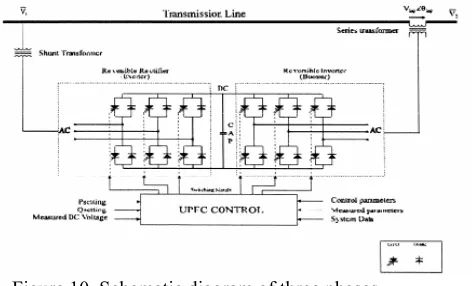
The UPFC consists of two voltage source converters; series and shunt converter, which are connected to each other with a common dc link. Series converter or Static Synchronous Series Compensator (SSSC) is used to add controlled voltage magnitude and phase angle in series with the line, while shunt converter or Static Synchronous Compensator (STATCOM) is used to provide reactive power to the ac system, beside that, it will provide the dc power required for both inverter. Each of the branches consists of a transformer and power electronic converter. These two voltage source converters shared a common dc capacitor. The energy storing capacity of this dc capacitor is generally small. Therefore, active power drawn by the shunt converter should be equal to the active power generated by the series converter. The reactive power in the shunt or series converter can be chosen independently, giving greater flexibility to the power flow control. The coupling transformer is used to connect the device to the system. Figure .10. Shows the schematic diagram of the three phases UPFC connected to the transmission line.
Figure 10. Schematic diagram of three phases
UPFC connected to a transmission line
25 Figure 11 Equivalent single line circuit diagram
representation of UPFC in power systems
Fig.12 UPFC model schematic
Fig.13 UPFC model equivalent
The sending end of the UPFC is transformed into a PQ bus, whilst the receiving end is transformed into a PV bus. The active and reactive power loads in the PQ bus are set to the values being controlled by the UPFC. The voltage magnitude at the PV bus
is set at the value to be controlled by the UPFC. A
standard load flow solution is carried out with the equivalent model given in Fig. 5. After load flow convergence, an additional set of nonlinear equations is solved by iteration to compute the UPFC parameters. This method is simple but will only work if the UPFC is used to control voltage magnitude, active power and reactive power, simultaneously. If one only wishes to control one or two variables, the method is no longer applicable. Moreover, since the UPFC parameters are computed after the load flow has converged, there is no way of knowing during the iterative process whether or not the UPFC parameters are within limits.
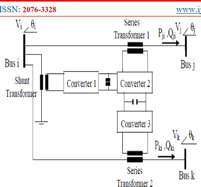
G. Interline Power Flow Controller (IPFC) [78]-[81]
Generally, the Interline Power Flow Controller (IPFC) is a combination of two or more independently controllable static synchronous series compensators (SSSC) which are solid-state voltage source converters which inject an almost sinusoidal voltage at variable magnitude and couples via a common DC link as shown in Figure1.Conventionally, series capacitive compensation fixed, thyristor controlled or SSSC based, is employed to increase the transmittable real power over a given line and to balance the loading of a normally encountered multi-line transmission system. They are controlled to provide a capability to directly transfer independent real power between the compensated lines while maintaining the desired distribution of reactive flow among the line. The figure 14 and 15 shows the Simplified schematic of two-converter IPFC model and basic Two-Inverter Interline Power Flow Controller respectively.
Fig.14. Simplified schematic of two-converter IPFC model
Fig. 15. Basic Two-Inverter Interline Power Flow Controller.
26 Fig. 16. Equivalent Circuit diagram of the IPFC
Fig.17. Power injection model of two converters IPFC
H. Generalized Unified Power Flow Controller (GUPFC) [82]-[84]
1. Operating Principles of GUPFC:
An innovative approach to utilization of FACTS controllers providing a multifunctional power flow management device. There are several possibilities of operating configurations by combing two or more converter blocks with flexibility. Among them, there are two novel operating configurations, namely the Interline Power Flow Controller (IPFC) and the Generalized Unified Power Flow Controller (GUPFC), which are significantly extended to control power flows of multi-lines or a sub-network rather than control power flow of single line by a Unified Power Flow Controller (UPFC) or Static Synchronous Series Compensator (SSSC).
In contrast to the practical applications of the GUPFC in power systems, very few publications have been focused on the mathematical modeling of this new FACTS controller in power system analysis. A fundamental frequency model of the GUPFC consisting of one shunt converter and two series converters for EMTP study was proposed quite recently in open literatures. While modeling the GUPFC in power flow, optimal power flow
(OPF) analysis has not been reported yet. Therefore, in open literatures, a mathematical model of the GUPFC suitable for power flow and optimal power flow study is established. In the past three decades, techniques such as Newton method, sequential linear and quadratic programming method, PQ de-coupling method, etc. Have been used to solve optimal power flow problems.
The GUPFC with combing three or more converters working together extends the concepts of voltage and power flow control beyond what is achievable with the known two-converter UPFC FACTS controller [1], [2]. The simplest GUPFC consists of three converters, one connected in shunt and the other two in series with two transmission lines in a substation [5]. It can control total five power system quantities such as a bus voltage and independent active and reactive power flows of two lines. Such a GUPFC, which is shown in Fig. 18, is used to show the basic operation principle for the sake of simplicity. However, the mathematical derivation is applicable to a GUPFC with an arbitrary number of series converters.
In the steady state operation, the main objective of the GUPFC is to control voltage and power flow. The equivalent circuit of the GUPFC consisting of one controllable shunt injected voltage source and two controllable series injected voltage sources is shown in Fig. 19. Real power can be exchanged among these shunt and series converters via the common DC link. The sum of the real power exchange should be zero if we neglect the losses of the converter circuits. For the GUPFC shown in Figs. 18 and 19, it has total 5 degrees of control freedom, which means it can control five power system quantities such as one bus voltage, and 4 active and reactive power flows of two lines. It can be seen that with more series converters included within the GUPFC, more degrees of control freedom can be introduced and hence more control objectives can be achieved.
27 Fig. 18: Basic circuit arrangement of GUPFC
Fig. 19. The equivalent circuit of the GUPFC
I. Hybrid Power Flow Controllers (HPFC)[85]
In [1], introduced a hybrid flow controller (HFC) as a new member of flexible ac transmission system (FACTS) controllers for steady-state and power-flow control of power transmission lines. HFC is a hybrid compensator (i.e., provides series and/or shunt compensation). Structurally, an HFC unit is composed of a mechanically switched phase-shifting transformer, a mechanically switched shunt capacitor, and multi-module, series-connected, thyristor-switched capacitors and inductors. In [1], described the steady-state operation, single-phase equivalent circuit,
power-flow model, and V-I and P-Q characteristics of the
HFC. In [1], highlighted the steady-state technical features of the HFC for power-flow control of a study system and also provides a quantitative comparison of the HFC, UPFC, and PST.
In [1], introduced a hybrid flow controller (HFC) as a new FACTS controller and: 1) describes its steady-state principles of operations; 2) develops
its single-line equivalent circuit and power-flow model; and 3) investigates its steady-state power-flow control characteristics. Conceptually, HFC is not a new circuit configuration and rather an amalgamation of existing and well established power-flow controllers, that is,
• conventional mechanically switched
phase-shifting transformer (PST);
• a conventional mechanically switched
shunt capacitor (MSC);
• a multi-module thyristor-switched series
capacitor (TSSC);
• a multi-module thyristor-switched series
reactors (TSSR).
TSSC and TSSR subsystems of an HFC are electronically switched, and thus are adequately fast to 1) respond to system dynamics and 2) provide dynamic power-flow control. However, this paper investigates only steady-state behavior and characteristics of an HFC. Due to the inherent discrete operational nature of the HFC, its dynamic control and behavior are best investigated based on a discrete-event supervisory control strategy and will be the subject of a separate article.
HFC belongs to the family of hybrid compensators since it provides power-flow control through series and/or shunt compensation, analogous to the unified power-flow controller (UPFC). Although HFC does not offer all versatility and technical features of the UPFC, its salient features make it an alternative to the UPFC. These features are:
• cost effectiveness;
• simplicity of concept, control, and
operational strategies;
• maturity and ruggedness of the
technologies of its various subsystems;
• lower losses and, thus, higher efficiency.
HFC provides economical incentive in a scenario that an existing PST is augmented with TSSC and/or TSSR modules to form an HFC. Furthermore, since TSSC and TSSR modules are not phase-controlled and only switched in and out by thyristor switches, HFC does not generate harmonics and has no adverse impact on power quality.
28 Fig. 1 shows a schematic diagram of an HFC that is connected between buses i and j within a transmission line and is comprised
of:
• a PST which can inject a lead/lag,
quadrature-phase voltage;
• multimodule TSSC system that can insert
a variable series capacitive reactance, in discrete steps, to adjust the line series reactance;
• multimodule TSSR system that can insert
a variable series inductive reactance, in discrete steps, to prevent overflow;
• an MSC for reactive power compensation.
Due to their inherent large time-constants, PST and MSC can only impact steady-state power flow, while the TSSC and the TSSR modules can provide both dynamic and steady-state power-flow control. By replacing one TSSC module with a thyristor-controlled series capacitor (TCSC) module, continuous control of series reactance also can be achieved.
Based on the configuration of Fig. 20, a per-phase schematic representation of the HFC is given in Fig. 21. The details to reduce the single-phase PST of Fig. 2 from that of Fig. 1, under balanced conditions. The extraction of per phase representations of the TSSC, TSSR, and MSC of Fig. 2 from those of Fig. 20, under a balanced condition.
Fig. 20. Schematic diagram of an HPFC.
Fig. 21. Per-phase schematic representation of HPFC.
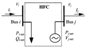
2. Steady-state V -I characteristic of HPFC:
A steady-state V−Icharacteristic of the HFC of
Fig. 2 is shown in Fig. 3. Viand V j voltage phasors
of buses i and j, respectively. The PST injects
quadrature-phase voltage Vp, and
' i
V is the
voltage of the HFC internal bus (i.e., i’ bus ) (Fig. 2).
A steady-state V−I characteristic of the HFC of
Fig. 2 is shown in Fig. 3. Viand Vjare voltage
phasors of buses i and j , respectively. The PST
injects quadrature-phase voltage Vp, and
' i
V is the
voltage of the HFC internal bus (i.e., bus i’) (Fig.
2). In Fig. 3(a), the phasor of line current Iijis
lagging Vi by angle
ϕ
. Fig. 3(a) also shows theTSSC voltage VXCfor
ϕ
=
0
oand,ϕ ϕ
=
m, andthe corresponding voltage at bus j (i.e., Vj),
corresponding to a pre-specified reactance of
MSC. Magnitude of VXCdepends on 1) the
magnitude of line current Iijand 2) the number of
TSSC modules in service.
It should be noted that the TSSC is less effective to control real power flow when the line current is small. However the magnitude of the injected voltage by the PST is almost independent of the line current and can be controlled only by the PST
voltage ratio, from 0 toVpmax . As a result, for those
29 The Fig. 22(a) & (b) shows the steady-state V-I characteristics of HPFC.
(a)
(b)
Fig. 22. Steady-state V -I characteristic of HPFC, (a) TSSC in service. (b) TSSR in service.
Fig. 3(b) shows a V−I characteristic of the HFC
when the TSSC modules are shorted and the TSSR is operational. Fig. 3(b) shows TSSR voltage
phasor VXLfor
0
o
ϕ
=
and,ϕ ϕ
=
m, and thecorresponding aVjbus j. A combination of shaded
areas A and D of Fig. 22 specifies the - area that the HFC can control the line power flow. If the PST is capable of injecting lagging quadrature
voltage, the corresponding V−Icharacteristics
regions are added to regions A and B of Fig. 3 to
determine the overall V−I area.
3. Power-flow model of HPFC:
Conceptually, there are three approaches to develop an HFC model for power-flow analysis. The first one is the classical approach which is based on augmenting the system matrix to include the HFC model. The drawback of this approach is that the augmented becomes asymmetrical, and thus can be used neither in a decoupled power-flow
analysis, nor for efficient storage. The power flow model of HPFC shown in fig. 23.
Fig. 23. Power-flow model of HPFC.
3. CONCLUSIONS
This paper presents the introduction of various FACTS controllers such as SVC, TCSC, TCPAR or TCPAT, SSSC, STATCOM, UPFC, IPFC, GUPFC, HPFC for operation, control, planning & protection from different performance point of view such as increased the loadability, improve the voltage profile, minimize the active power losses, increased the available transfer capacity, enhance the transient and steady-state stability, and flexible operations of power systems. Also this paper presents the current status on the introduction of various FACTS controllers such as SVC, TCSC, TCPAR or TCPAT, SSSC, STATCOM, UPFC, IPFC, GUPFC, HPFC for operation, control, planning & protection from different performance point of view such as increased the loadability, improve the voltage profile, minimize the active power losses, increased the available transfer capacity, enhance the transient and steady-state stability, and flexible operations of power systems.
ACKNOWLEDGMENT
The authors would like to thanks Dr. S. C. Srivastava, and Dr. S. N. Singh, Indian Institute of Technology, Kanpur, U.P., India, for their valuables suggestions regarding for FACTS controllers.
REFERENCES
[1] N. Hingorani and L. Gyugyi, Understanding
FACTS—Concepts and Technology of Flexible AC Transmission Systems.
Piscataway, NJ:IEEE Press/Wiley, 2000.
[2] Claudio A. Canizares, and Zeno T. Faur, “
30 Voltage Collapse,” IEEE Trans on Power Systems, Vol. 14, No. 1, February 1999.
[3] Ashwani kumar Sharma,“Optimal Number
and Location of TCSC and Loadability Enhancement in Deregulated Electricity Markets Using MINLP,” International Journal of Emerging Electric Power Systems, Vol.5, Issue 1, 2006.
[4] Guang Ya Yang, Geir Hovland, Rajat
Mujumder, and Zhao Yang Dong, “TCSC Allocation Based on Line Flow Based Equations Via Mixed-Integer Programming,” IEEE Trans on Power Systems, Vol.22, No.4, November 2007.
[5] Srinivasa Rao Pudi, and S.C.Srivastava,
“Optimal Placement of TCSC Based on A Sensitivity Approach for Congestion Management,” Fifteenth National Power Systems Conference (NPSC), IIT Bombay, December 2008, pp.558-563.
[6] S.Gerbex, R. Cherkaoui, and A.J.Germond,
“Optimal Location of Multi-Type FACTS Devices in a Power System by Means of Genetic Algorithms,” IEEE Trans. on Power Systems, vol.16, No.3, pp. 537-544, August 2001.
[7] A. Kazemi, and B. Badrzadeh, “Modeling
and Simulation of SVC and TCSC to Study Their Limits on Maximum Loadalibility Point,” Electrical Power & Energy Systems, Vol. 26, pp. 619-626, 2004.
[8] J.G. Singh, S. N. Singh, and S. C. Srivastava,
“Placement of FACTS Controllers for Enhancing Power System Loadability”, IEEE Trans. on Power Delivery, Vol. 12, No.3, July 2006.
[9] B. Chaudhuri, and B. C. Pal, “Robust
Damping of Multiple Swing Modes Employing Global Stabilizing Signals with a TCSC,” IEEE Trans on Power Systems, Vol. 19, No.1, February 1999.
[10] S. N. Singh and A. K. David, “A new
approach for placement of FACTS Devices in Open Power Market,” IEEE Power Engg. Rev., 2001, 21(9), pp. 58-60.
[11] N. K. Sharma, A. Ghosh, and R. K. Verma,
“A Novel Placement Strategy for FACTS Controllers”, IEEE Trans. on Power Delivery, Vol. 18, No.3, July 2003.
[12] W. H. Litzenberger, R. K. Verma and J. D.
Flanagan, “An Annotated Bibliography of HVDC transmission and FACTS Devices 1996-1997,” Electric Power Research Institute, WO-3022 06 , June 1998.
[13] E. J. Oliveira, J. W. M. Lima, and K de.
Almeida, “Allocation of FACTS devices in Hydrothermal Systems,” IEEE Trans. on Power Systems, Vol. 15, No.1, pp. 276-282, February 2000.
[14] Tjing T. Lie and Wanhong Deng, “Optimal
Flexible AC Transmission Systems (FACTS) Devices Allocation,” Electrical Power & Energy Systems, Vol. 19, No.2, pp. 125-134, 1997.
[15] J.J. Sanchez-Gasca, “Coordinated Control of
two FACTS devices for Damping Inter-area Oscillations,” IEEE Trans. on Power Systems, Vol.13, No.2, pp. 428-434, May 1998.
[16] Ping Lam So, Yun Chung Chu, and Tao Yu,
“Coordinated Control of TCSC and SVC for system Damping Enhancement,” International Journal of Control Automation and Systems, Vol. 3, No.2, (special edition), pp. 322-333, June 2005.
[17] L. J. Cai, and I. Erlich, “Fuzzy Coordination
of FACTS Controllers for Damping Power Oscillations,” IEEE Trans. on Power Systems, Vol. 21, No.3, 2006.
[18] Dheeman Chatterjee and Arindam Ghosh,
“Application of Trajectory Sensitivity for the Evaluation of the Effect of TCSC Placement on Transient Stability,” International Journal of Emerging Electric Power Systems, Vol. 8, Issue 1, 2007.
[19] A. Kumar, S. C. Srivastava, and S. N. Singh,
“Impact of TCPAR on Cluster-Based Congestion Management Using Improved Performance Index,” Iranian Journal of Electrical and Computer Engineering, Vol. 7, No. 2, Summer-Fall 2008, pp.89-97.
[20] R. K. Verma, “Control of Static VAR
systems for Improvement of Dynamic Stability and Damping of Torsional Oscillations,” Ph. D. Thesis, IIT Kanpur, April 1998.
[21] Yuan-Lin Chen, “Weak Bus-Oriented
Optimal Multi-Objective VAR Planning,” IEEE Trans on Power Systems, Vol. 11, No.4, November 1996.
[22] R. M. Hamouda, M. R. Iravani, and R.
Hacham, “Coordinated Static VAR Compensators for Damping Power System Oscillations,” IEEE Trans. on Power Systems, Vol. PWRS-2, No.4, November 1987.
[23] W. Zhang, F. L., and Leon M. Tolbert,
31 IEEE Trans on Power systems, Vol.22, No. 3, Oct 2007.
[24] Y. Mansour, W. Xu. F. Alvarado, and C.
Rinzin, “SVC Placement Using Critical Modes of Voltage Stability,” IEEE Trans. on Power Systems, Vol. 9, pp. 757-762, May 1994.
[25] Cigre Working Group, “Modeling of Static
VAR Systems for Systems Analysis,” Electra, Vol. 51, pp.45-74, 1977.
[26] Malihe M. Farsangi, Hossein
Mezamabadi-pour, “Placement of SVCs and Selection of Stabilizing Signals in Power Systems, “IEEE Trans. on Power Systems, Vol. 22, No. 3, August 2007.
[27] Roberto Mingues, Federico Milano, Rafael
Zarate-Minano, and Antonio J. Conejo, “Optimal Network Placement of SVC Devices,” IEEE Trans. on Power Systems, Vol.22, No.4, November 2007.
[28] Y. Chang, “Design of HVDC and SVC
Coordinate Damping Controller Based on Wide Area Signal,” International Journal of Emerging Electric Power Systems, Vol. 7, Issue 4, 2006.
[29] N. Martins and L. T. G. Lima,
“Determination of Suitable Locations for Power System Stabilizers and Static Var Compensators for Damping Electro-mechanical Oscillation in large Scale Power Systems,” IEEE Trans. on Power Systems, Vol. 5, No.4, pp. 1455-1469, November 1990.
[30] M. K. Verma, and S. C. Srivastava,
“Optimal Placement of SVC for Static and Dynamic Voltage Security Enhancement,” International Journal of Emerging Electric Power Systems, Vol.2, issue-2, 2005.
[31] C. S. Chang, and J. S. Huang, “Optimal SVC
Placement for Voltage Stability Reinforcements,” Electric Power System Research, Vol.42, pp.165-172, 1997.
[32] Mohd WAzir Mustafa, and Wong Yan
Chiew, “Optimal Placement of Static VAR Compensator Using Genetic Algorithms,” Elektrika, Vol. 10, No.1, pp.26-31, 2008.
[33] Z. Y. Dong, Y. Wang, D. J. Hill, and Y. V.
Makarov, “ A New Approach to Power Systems VAr Planning Aimed at Voltage Stability Enhancement with Feedback Control,” In Proc. 1999, Electric Power Engineering Power Tech.Budapest’99, pp.33-39.
[34] V.Ajjarapu, Ping Lin Lau, and S. Battula,
“An Optimal Reactive Power Planning
Strategy Against Voltage Collapse,” IEEE Trans on Power Systems, Vol.9, No.2, May 1994.
[35] L. Gyugi, N. G. Hingorani, P. R. Nannery,
and N. Tai, “Advanced Static VAR Compensator Using Gate Turn-off Thyristor for Utility Applications,” CIGRE,23-203, 1990 Session, Paris.
[36] Jing Zhang, J. Y. Wen, S. J. Cheng, and Jia
Ma, “A Novel SVC Allocation Method for Power System Voltage Stability Enhancement by Normal Forms of Diffeomorphism,” IEEE Trans. on Power Systems, Vol. 22, No. 4, November 2007.
[37] Youyi wang, Yoke Lin Tan, and Guoxiao
Guo, “Robust Non-linear Coordinated Excitation and SVC Control for Power
Systems,” In Proc. of the 4th International
Conf. on Advances in Power System Control , Operation and Management, APSCOM’97, Hong Kong, Nov. 1997.
[38] J. V. Milanovic, and I. A. Hiskens,
“Damping Enhancement by Robust Tuning of SVC Controllers in the Presence of load Parameters Uncertainty,” IEEE Trans on Power Systems, Vol.13, No.4, November 1997.
[39] L. J. Cai, and I. Erlich, “Simultaneous
Coordinated Tuning of PSS and FACTS Damping Controllers in Large Power Systems,” IEEE Trans. on Power Systems, Vol. 20, No. 1, February 2005.
[40] M. W. Mustafa, Nuraddeen Magaji, and
“Optimal Location of Static Var Compensator Device for Damping Oscillations,” American Journal of Engineering and Applied Sciences, Vol. 2, No.2, 2009.
[41] Ying-Yi Hong, and Chen-Ching Liu, “A
heuristic and Algorithmic Approach to VAR Planning,” IEEE Trans on Power Systems, Vol. 7, No.2, May 1992.
[42] O. Zhao, and Jin Jiang ,“Robust SVC
Controllers Design for Improving Power System Damping,” IEEE Trans on Power Systems, Vol. 10, No.4, November 1995.
[43] X. Yu, M. Khammash, and V. Vittal,
“Robust Design of a Damping Controller for Static Var Compensators in Power Systems,” IEEE Trans on Power Systems, Vol. 16, No.3, August 2001.
[44] C. P. Gupta, “Voltage Stability Margin
32
[45] N.K.Sharma, “A Novel Placement Strategy
for FACTS Controllers in Multi-machine Power Systems,” Ph. D. Thesis, IIT Kanpur, India, 2003.
[46] Liu Jun, Tang Guangfu, and Li Xingyuan,
“Interaction Analysis and Coordination Control between SSSC and SVC,” Power System Technology, 2006, POWERCON’2006, International Conference, 22-26 Oct., 2006, pp.7-10.
[47] X. P. Zhang, “Advanced modeling of the
multi-control functional static synchronous series compensator (SSSC) in Newton
power flow,” IEEETrans. Power Syst., vol.
18, no. 4, pp. 1410–1416, Nov. 2003.
[48] K. K. Sen, “SSSC-static synchronous series
compensator theory, modeling, and
application,” IEEE Trans. Power Del., vol.
13, no. 1, pp. 241–246, Jan. 1998.
[49] K.K. Sen , “STATCOM-static synchronous
compensator theory, modeling, and
applications,” in Proc. IEEE Power Eng.
Soc. Winter Meeting, 1999, vol. 2, pp. 1177–
1183.
[50] C. Schauder, M. Gernhardt, E. Stacey, T.
Lemak, L. Gyugyi, T. W. Cease, and A. Edris, “TVA STATCOMproject: design, installation, and commissioning,” presented at the CIGRE Meeting, Paris, France, Aug. 1996, Paper 14-106, unpublished.
[51] S. A. N. Niaki, “Modeling and applications
of unified power flow controller (UPFC) for power systems,” Ph.D. dissertation, Dept. Elect. Comput. Eng., Univ. Toronto, Toronto, ON, Canada, 1996.
[52] K. S. Verma and H. O. Gupta, “Impact on
Real and Reactive Power Pricing in Open Power Market Using Unified Power Flow Controller,” IEEE Transactions On Power Systems, Vol. 21, No. 1, February 2006, pp.365-371.
[53] K. K. Sen, “UPFC-unified power flow
controller theory-modeling and
applications,” IEEE Trans. Power Del., vol.
13, no. 4, pp. 1453–1460, Oct. 1998.
[54] A.Nabavi-Niaki, and M.R. Iravani,
“Steady-State and Dynamic Models of UPFC for Power System Studies,” IEEE Trans. on PS, Vol. 11, No. 4, pp. 1937-1943, Nov. 1996.
[55] Seungwon An, John Condren, and Thomas
W. Gedra, “An Ideal Transformer UPFC
Model, OPF First-Order Sensitivities, and Application to Screening for Optimal UPFC Locations,” IEEE Transactions On Power
Systems, Vol. 22, No. 1, February 2007, pp.68-75.
[56] J. Y. Liu, Y. H. Song, and P. A. Mehta,
“Strategies for handling UPFC constraints in steady—State power flow and voltage
control,” IEEE Trans. Power Syst., vol. 15,
no. 2, pp. 566–571, May 2000.
[57] S.M. Alamelu, and R. P. Kumudhini Devi,
“Novel Optimal Placement UPFC Based on Sensitivity Analysis and Evolutionary Programming ,” Journal of Engineering and Applied Sciences, Vol.3, No.1, pp.59-63, 2008.
[58] Srekanth Reddy Donapati, and M. K.
Verma, “An Approach for Optimal Placement of UPFC to enhance Voltage Stability Margin under Contingencies,” Fifteenth National Power Systems Conference (NPSC), IIT Bombay, December 2008 pp.441-446.
[59] S. N. Singh, and I. Erlich, “ Locating
Unified Power Flow Controllers for Enhancing Power System Loadability,” Future Power Systems, 2005, International Conference , 18 Nov 2005, pp 5-5.
[60] H.I. Shaheen, G. I. Rashed, and S.J. Cheng,
“Optimal Location and Parameters Setting of UPFC based on GA and PSO for Enhancing Power System Security Under Single Contingencies,” Power and Energy Society General Meeting-Convesion and
delivery of Electrical Energy in The 21st
Century, 2008,IEEE, 20-24 July, 2008, pp.1-8.
[61] B. A. Renz, A. Keri, A. S. Mehraban, C.
Schauder, E. Stacey, L. Kovalsky, L. Gyugyi, and A. Edris, “AEP unified power
flow controller performance,” IEEE Trans.
Power Del., vol. 14, no. 4, pp. 1374–1381,
Oct. 1999.
[62] L. Ippolito, “ A novel Strategy for Selection
of the Optimal Number and Location of UPFC devices in Deregulated Electric Power Systems,” Power Tech, 2005, IEEE Russia, 27-30 June, 2005, pp.1-9.
[63] W.L.Fang, and H. W. Ngan, “Optimizing
location of UPFC using the Methods of Augmented Lagrange Multipliers,” IEE Proc.,Gener., Transm.,Distrib.,Vol 146, No.5, Sep. 1999.
[64] K. Visakha, D. Thukaram, L. Jenkins, and
33 Technologies for Asia –Pacific Region, Vol-2, 15-17 Oct, 2003, pp755-760.
[65] D. Thukarana, L. Jenkins, and K. Visakha,
“Improvement of System Security with UPFC at Suitable Locations Under Network Contingencies of Interconnected Systems,” IEE Proc., Gener., Transm., Distrib., Vol. 152, No.5, Sep 2005.
[66] R.P.Kalyani, M. L. Crow, and D. R. Tauritz,
“Optimal Placement and Control of UPFC devices Using Evolutionary Computing and Sequential Quadratic Programming,” Power Systems Conference and Exposition 2006, PSCE’06, 2006 IEEE PES, 29 Oct.,2006- 1 Nov.,2006, pp 959-964.
[67] J. G. Singh, S. N. Singh, and S. C.
Srivastava, “Optimal Placement of Unified Power Flow Controller Based on System Loading Distribution Factors,” Electric Power Components and Systems, Vol. 37, Issue 4, April 2009, pp.441-463.
[68] J. Bian, D. G. Ramey, R. J. Nelson, and A.
Edris, “A study of equipment sizes and constraints for a unified power flow
controller,” IEEE Trans. Power Del., vol.
12, no. 3, pp. 1385–1391, Jul. 1997.
[69] R. L. Vasquez-Arnez and L. C. Zanetta, “A
novel approach for modeling the steady-state VSC-based multiline facts controllers
and their operational constraints,” IEEE
Trans. Power Del., vol. 23, no. 1, pp. 457–
464, Jan. 2008.
[70] C. D. Schauder, M. R. Lund, D. M. Hamai,
T. R. Rietman, D. R. Torgerson, and A. Edris, “Operation of the unified power flow controller (UPFC) under practical
constraints,” IEEE Trans. Power Del., vol.
13, no. 2, pp. 630–637, Apr. 1998.
[71] H. Ambriz-Perez, E. Acha, C. R.
Fuerte-Esquivel, and A. De la Torre, “Incorporation of a UPFC model in an optimal power flow
using Newton’s method,” Proc. Inst. Elect.
Eng., Gen., Transm., Distrib., vol. 145, no.
3, pp. 336–344, May 1998.
[72] C. R. Fuerte-Esquivel, E. Acha, and H.
Ambriz-Perez, “A comprehensive Newton-Raphson UPFC model for the quadratic power flow solution of practical power
networks,” IEEE Trans. Power Syst., vol.
15, no. 1, pp. 102–109, Feb. 2000.
[73] M. Noroozian, L. Ängquist, M. Ghandhari,
and G. Andersson, “Use of UPFC for
optimal power flow control,” IEEE Trans.
Power Del., vol. 12, no. 4, pp. 1629–1634,
Oct. 1997.
[74] Christopher Collins, Neville Watson,and
Alan Wood, Member, “UPFC Modeling in
the Harmonic Domain,” IEEE Transactions On Power Delivery, Vol. 21, No. 2, April 2006, pp. 933-938.
[75] J. Monteiro, J. Fernando Silva, S. F. Pinto,
and J. Palma, “Matrix Converter-Based Unified Power-Flow Controllers: Advanced Direct Power Control Method,” IEEE Transactions On Power Delivery, Vol. 26, No. 1, January 2011, pp.420-430.
[76] B. Geethalakshmi and P. Dananjayan,
“Investigation of performance of UPFC
without DC link capacitor,” in Elect. Power
Energy Res.. New York: Elsevier, 2008, pp.
284–294, 736-746.
[77] X. Jiang, X. Fang, J. Chow, A. Edris, E.
Uzunovic, M. Parisi, and L. Hopkins, “A novel approach for modeling voltage-sourced converter based FACTS
controllers,” IEEE Trans. Power Del., vol.
23, no. 4, pp. 2591–2598, Oct. 2008.
[78] S. Ali Nabavi Niaki, Reza Iravani, and
Mojtaba Noroozian, “Power-Flow Model
and Steady-State Analysis of the Hybrid Flow Controller,” IEEE Transactions On Power Delivery, Vol. 23, No. 4, October 2008, pp.2330-2338.
[79] Suman Bhowmick, Biswarup Das, and
Narendra Kumar, “An Advanced IPFC Model to Reuse Newton Power Flow Codes,” IEEE Transactions On Power Systems, Vol. 24, No. 2, May 2009, pp. 525-532.
[80] Y. Zhang, Y. Zhang, and C. Chen, “A novel
power injection model of IPFC for power flow analysis inclusive of practical
constraints,” IEEETrans. Power Syst., vol.
21, no. 4, pp. 1550–1556, Nov. 2006.
[81] L. Gyugyi, K. K. Sen, and C. D. Schauder,
“The Interline Power Flow Controller concept: A new approach to power flow
management in transmission systems,” IEEE
Trans. Power Del., vol. 14, no. 3, pp. 1115–
1123, Jul. 1999.
[82] X. P. Zhang, “Modelling of the Interline
Power FlowController and the generalized unified power flow controller in Newton
power flow,” Proc. Inst. Elect. Eng., Gen.,
Transm., Distrib., vol. 150, no. 3, pp. 268–
274, May 2003.
[83] L. Gyugyi, C. D. Schauder, S. L. Williams,
34
control,” IEEE Trans. Power Del., vol. 10,
no. 2, pp. 1085–1097, Apr. 1995.
[84] Xiao-Ping Zhang, Edmund Handschin, and
Maojun “Mike” Yao, “Modeling of the
Generalized Unified Power Flow Controller (GUPFC) in a Nonlinear Interior Point OPF,” IEEE Transactions On Power Systems, Vol. 16, No. 3, August 2001, pp.367-373.
[85] S. Ali Nabavi Niaki, Reza Iravani, and
Mojtaba Noroozian,” Power-Flow Model
and Steady-State Analysis of the Hybrid Flow Controller”, IEEE Transactions On Power Delivery, Vol. 23, No. 4, October 2008, pp.2330-2338.
AUTHOR PROFILES:
Bindeshwar Singh received the M.Tech. in
electrical engineering from the Indian Institute of Technology (IIT), Roorkee, in 2001.He is now a Ph. D. student at GBTU, Lucknow, India. His research interests are in Optimal Placement of Distributed Generation & FACTS controllers in power Systems. Currently, he is an Assistant Professor with Department of Electrical Engineering, Kamla Nehru Institute of Technology, Sultanpur, U.P., India, where he has been since August’2009.
Email: [email protected]
K.S. Verma received his B. Tech. (Hons) in
Electrical Engineering and M. Tech. in Electrical Engineering (Power Systems) both from KNIT Sultanpur (India) in 1987 and 1998, respectively. He obtained his Ph.D. degree in Electrical Engineering (Power Systems) from Indian Institute of Technology, Roorkee. Roorkee India in 2003 Presently, Prof Verma is Director, KNIT Sultanpur (India). His research interests include FACTS Technology, distributed generation, power system optimization & control, power quality and AI application in power system
Email: [email protected]
Deependra Singh received the Ph.D. in electrical
engineering from the U.P. Technical University, Lucknow,U.P., India, in 2009. Currently, he is a Registrar with, Kamla Nehru Institute of Technology, Sultanpur, U.P., India, where he has been since January2010. His interests are in the areas of FACTS control and Power systems.
Email: [email protected]
C.N.Singh is a Associate Professor in the
department of Electrical Engineering at HBTI Kanpur, U.P., India. His research interests include FACTS Technology, distributed generation, power system optimization & control, and AI application in power system.
Archna Singh is a Associate Professor in the
department of Electrical Engineering at HBTI Kanpur, U.P., India. His research interests include FACTS Technology, power system optimization & control, and AI application in power system.
Ekta Agrawal is a Associate Professor in the
department of Applied Science (Mathematics Department) at BIET Jhansi, U.P., India. His research interests include mathematics, power system optimization & control, and AI application in power system.
Rahul Dixit is a M.Tech student (Regular) in
specialization of Power Electronics and Drives in electrical engineering department, KNIT sultanpur-228118(U.P.), India. His interests are in the areas of Power Electronics and Drives.
Baljeev Tyagi is a Professor in Electrical