ISSN (e): 2250-3021, ISSN (p): 2278-8719
Vol. 08, Issue 8 (August. 2018), ||V (II) || 29-35
Operational Programmable Logic Control of a Non-Disposable
Brake pad Sensor
A.A. Adeseko
1, B. Kareem
21
(Industrial and Production Engineering/ The Federal University of Technology, Akure, Nigeria.
2(Industrial and Production Engineering/ The Federal University of Technology, Akure, Nigeria.)
Corresponding Author: A.A. Adeseko1
Abstract :
The braking system is very important components in the motor vehicle without which the vehicle could possibly result in road accident. In this study, a non-disposable brake pad sensor was design and fabricated to enable imminent failure alert in order to reduce the risk of road accidents. The research approach involved development of both hardware and software components of the sensor. The hardware components include the microcontroller, contact sensor, battery, communication PC cable, capacitors and Tri-colour LED indicator while the software components include Mikro C Pro (to write the program and compile it). The test results indicated that, during normal operating condition, the Tri-colour LED emits green colour signifying that the brake pad is in good condition. The brake pad material worn to about 50% of its original thickness value indicated that the sensor has been contacted with the rotor thereby causing a closed circuit, on this basis, the LED energized to emit an amber appearance signifying that the pad should be replaced soon. The worn of the brake pad to about 25% of the frictional material led to emission red light which signifies that the pads need to be replaced.Keywords –
Accident, brake pad, Mikro C, Sensor, Tri-LED--- --- Date of Submission: 31-07-2018 Date of acceptance: 18-08-2018 --- ---
I.
INTRODUCTION
Road accidents have become a normal and re-occurring phenomenon in Nigeria which constitutes a menace in modern times. Although both the developed and developing nations of the world have suffered from varying degrees of road accidents, the developing countries clearly dominates with Nigeria having the second highest rate of road accidents among 193 ranked countries of the world [1]. The rate at which Nigerians perish in road crashes is alarming. Almost every day, we are awash with stories of road accidents that cost the lives of Nigerians and inflict temporary or permanent injuries on some others [2]. According to the figures by the Federal Road Safety Commission (FRSC), 10050 people die yearly in road accidents. Statistically, this means there are 28 deaths on our roads daily and this excludes hundreds of victims who suffer various degrees of injuries and permanent disabilities. According to [2], the repercussions of such accidents have been colossal. Despite the happiness and change of quality of family lives associated with owning a vehicle its possession has left many families bereft of the bread winners or loved ones. [3] Invented a brake wear sensor. The brake wear sensor in which a body of electrical insulating material mounts a pair of electrically conductive plates such that edges of the plates are spaced from each other at a surface of the body. The body has an external thread adapted to be received within an internally threaded opening in a brake pad to position the surface of the body and the edges of the plates adjacent to a braking surface of the brake pad. Electrical circuitry is connected to the plates for monitoring wear at the surface of the body as a function of the changes in capacitance between the plates and a gauge is coupled to the circuitry for indicating brake wear as a function of such changes in capacitance.
Wiley and Williams [4] invented a brake pad wear detection system. The brake wear detection system comprises a brake having a brake pad and a conductive braking face with the brake face engaging during braking. A sensor loop is embedded in the brake pad and positioned to be broken when the wear to the brake pad exceeds the working limit. An indicator means and a detecting means for operating the indicator were provided, the detecting means detecting contact between the sensor loop and the braking face as well as breakage of the sensor loop. From the existing literature, the brake pad sensor were positioned to be destroyed this necessitate the development of Non-disposable brake pad sensor.
II.
EXPERIMENT
Brake pads convert the kinetic energy of the vehicle to thermal energy through friction. Two brake pads are contained in the caliper, with their friction surfaces facing the rotor [6]. According to [7] of all the systems that make car, the brake system might just be the most important because the average driver uses the brakes about 75,000 times a year, making the brakes one of the most overworked parts of the car.
A brake pad consists of a friction material which is attached to a stiff back plate. Sometimes the friction material and back plate together are called a brake pad. A brake pad usually incorporates slots on its face and chamfers at the ends. A pad can have more than one slot and it could be arranged in different orientations. One purpose to incorporate chamfers and slots is to reduce squeal noise [8].
Fig. 1: Brake Pad Attached to a Back Plate [8].
Fig. 2: Different Configurations of Pads [8].
2.1
Brake Caliper Configuration and Design
A brake caliper which is mounted on upright mainly holds the friction pads, while the clamping force is applied by the piston. The pressure distribution over the friction pads must be uniform so as to ensure even pad wear and heat distribution. Braking torque generated being the key parameter in braking, must be greater than the torque required to stop the vehicle. This is achieved by applying clamping force on the brake rotor which causes reactive forces thereby inducing stresses in the caliper body. The applied clamping force results in frictional force and generates heat which is dissipated by rotor and pads i.e. the kinetic energy of a vehicle is converted into heat which increases the disc temperature. There are two major types of disc brake caliper, the fixed and the floating caliper design.
Fixed Caliper Design: Fixed calipers tend to be larger and are mostly used on high-performance application. In these types of design, the caliper body is fixed and uses two or more pistons on each side of the rotor [9]. Fixed type caliper has pistons on both sides of the rotor and can be directly fixed to the mountings on the uprights. Pistons from both sides from the friction pads to apply force on the rotor [10].
Advantages of these brakes are:
b) Strength and heat dissipating ability ideal for heavy duty c) Rigid mounting and low flexibility
d) Firm and linear pedal feel Some Drawbacks are:
a) High weight of caliper b) High cost
c) Complexity
d) Higher chances of leaks
1. Brake pads 2. Pistons 3. Brake disc 4. Fixed caliper
Fig. 3: Fixed Caliper Design [11].
Floating Caliper Design: Floating caliper are smaller, lighter, and are widely used on most passenger cars and the light trucks in service today because floating calipers are less susceptive to pulsation from rotor run out. This type of brake uses only a single piston to squeeze the brake pad against the rotor [9]. In a floating caliper, piston is on the inboard side of the caliper while the caliper is mounted on a guiding pin which acts as a cylindrical support. The guiding pin allows linear movement of the caliper along its axis. The friction pads on the outboard side are continuously in contact with the brake rotor which prevents the bending of the rotor [10].
The benefits are:
a) Compact design dimension b) Low weight
c) Simple construction d) Low Prices
The associated drawbacks are:
1) Allows some freedom in caliper suspension that might deteriorate pedal feel.
2) Caliper suspension allows body to twist slightly during braking that can lead to taper lining wear. 3) Slow transfer of heat.
Fig. 4: Single-Piston Floating Caliper Disc Brakes [12].
III.
SENSOR SYSTEMS
Sensors are essential component in the operation of engineering devices, and are based upon a very wide range of underlying physical principles of operation [13].
device that receives a physical, chemical or biological signal and converts it into an electric signal that could be compatible with electric circuits.
3.1
Sensor Classification
Generally, sensors can be classified into many types based upon the applications, input signal, and conversion mechanism [14].
Table 3.1: Classification of Sensor
Types Detention Properties
Thermal sensor Temperature, Specific heat etc Electrical sensor Charge, Current, Inductance etc Magnetic sensor Magnetic flux density etc Optical sensor Light intensity, wavelength etc Mechanical sensor Acceleration, Flow, Pressure etc Chemical sensor Composition, pH, Concentration etc
3.2
Construction and Implementation of the Device
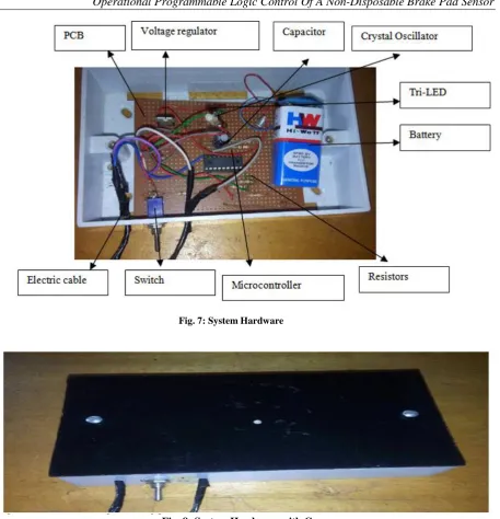
The materials used for the construction of the circuits are resistors, capacitors, power supply, Tri-LED indicator, crystal sensors and voltage regulator. The various components were bought and soldered. The system was operated on 9V supply.
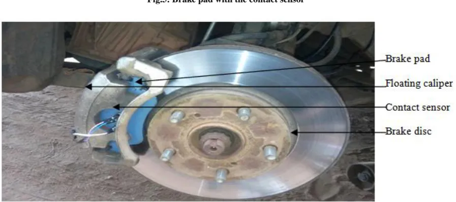
A drill bit of 12mm was drilled on the brake pad to accommodate the sensor. The contact sensor was 11mm. Modification was done on the brake pad. The sensor was glued into the brake pad. The brake pad consists of the outer and inner pad. The outer pad housed the sensor because of the design of the caliper. The indicator was placed on the dash board visible to the driver. The hardware set up for the Non-Disposable brake pad sensor is shown in fig. 5-8.
Fig.5: Brake pad with the contact sensor
Fig. 8: System Hardware with Cover
3.3 System Testing
The developed system can be tested practical application on vehicle. The practical application was tested for functional performance with a Toyota corolla, 2008 model car. The sensor was embedded in the brake pad and it was located at the left front outer pad. The brake pads are fixed into the caliper assembly, the system is switched-on and the determination of the brake pad life and remaining time for replacement are shown on the system.
IV.
RESULT AND DISCUSSION
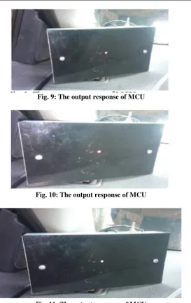
The output response of the microcontroller unit when implemented gives a desirable result. The MCU was placed on the left-hand side of the dash board. The MCU displays a green light when its newly installed as shown in Fig. 5. Basically, the drivers are not aware about the dangers of driving with a worn out brake pad, in view of this, the sensor was placed to about 50% of the frictional materials of the brake pad. The MCU displays amber light when the brake pad worn to about 50% of the brake pad as shown in Fig. 6.
According to Bridge stone tire, when the frictional material of the brake pad is about 3mm, it should be discarded. However, for safety purposes, the MCU displays a red light when the brake pad worn to about 25% of the frictional materials as shown in Fig. 7 and a need for replacement to avert accidents.
Fig. 9: The output response of MCU
Fig. 10: The output response of MCU
Fig. 11: The output response of MCU
V.
CONCLUSION
From the results and discussion of the research work, the conclusions is that during normal operating conditions when the new brake pad has been installed, the Tri-color LED emits green colour signifying that the pad is in good condition and in particular, the integrity of the sensor connection is maintained. However, when the brake pad worn to about 50% of the frictional material, it was observed that the contact sensor engaged the rotor thereby causing a closed circuit thus, the LED energized to emit an amber appearance signifying that the pad should be replaced soon. In the same vein, when the brake pad worn to about 25% of the frictional material, the contact sensor also engaged the rotor, causing a closed circuit with the LED energized to emit a red colour which signifies that the pad needs to be replaced in order to prevent damage to the braking system.
ACKNOWLEDGEMENT
I would like to thank Prof. B. Kareem for his support and guidance.
REFERENCE
[1]. Agbonkhese, O., Yisa, G.L., Agbonkhese, E.G., Akanbi, D.O., Aka, E.O., and Mondigha, E.B, Road Traffics in Nigeria:Causes and Preventive Measures. International Institute for Science, Technology and Education. Civil Environmental Research ISSN 2224-5790 (Paper) ISSN 2225-0514(Online) Vol. 3, No.13, 2013.
International organization of Scientific
Research 35 | P a g e
[3]. Paielle, P.M, Brake wear sensor, (U.S patent No. 6,384,721. Washington, DC: U.S. Patent and Trademark Office, 2002).
[4]. Wiley, D. and Williams, D.G., Brake Pad Wear Sensing System and Method (U.S. Patent No. 4204190. Washington, D.C: U.S. Patent and Trademark Office 1980).
[5]. Adeyemi, I.O., Nuhu, A.A., Thankgod, E.B, Development of Asbestos-free Automotive Brake pad using Ternary Agro-waste Fillers. Journal of Multidisciplinary Engineering Science and Technology (JMEST) ISSN: 2458-9403 Vol.3 Issue 7, pp. 5307-5323.
[6]. Henderson, B. and Haynes, J. H, "Disc Brakes". The Haynes Automotive Brake Manual,( Haynes, North America, pp. 1–20 1994).
[7]. McPhee A.D, Johnson D.A, Experimental heat transfer and flow analysis of a vented brake rotor. International Journal Thermal Science 47(4) pp. 458–467, 2007.
[8]. Rashid, Asim.: Overview of disc brakes and related phenomena - A review. International Journal of Vehicle Noise and Vibration, Vol.10 (4) pp.257301,2014.Availablefrom:https://www.researchgate.net/publication/280761396_Overview_of_disc _brakes_and_related_phenomena_-_A_review .accessed 30-06-2018.
[9]. Sarvendra, K.M, “A review of experimental study of brake pad material”. International Journal of Emerging Trends in Engineering and Development, Vol. 6, Issue 3, pp. 252-254, 2013.
[10]. Rathin, S., Chimmay, S., and Swapnil T, Design and Analysis of a hydraulic Brake pad caliper. International Journal of Mechanical Engineering and Technology (IJMET) Vol. 8, Issue 5, pp. 33-41, 2017.
[11]. Nikhil, P.W, Design and Analysis of modular caliper assembly. A Thesis at Witchita State University. www.soar.wichita.edu/bitstream/handle/10057/t05037.pdf?sequence=3, 2002..
[12]. Prashant Patel and Prof. Mohite M.A., Design optimization of passenger car front brake disc for improvement in thermal behavior, weight & cost reduction. Department of Mechanical Engineering, Sinhgad Institute of Technology Lonavala. International Journal of Engineering Development and Research, Volume 5, Issue 2 pp. 1079- 1086, 2017.
[13]. Shieh, J., Hubers, J.E., Fleck, N.A and Ashby,M.F, The selection of sensors. Department of Engineering, Cambridge University, Trumpington street. Progress in material science Vol. 46 pp. 461-504 Cambridge CB2 1PZ, UK, 2001.
[14]. Fraden, J, “Handbook of Modern Sensor”. Physics, Design and Application (AIP press, 2nd edition, 1997).
![Fig. 1: Brake Pad Attached to a Back Plate [8].](https://thumb-us.123doks.com/thumbv2/123dok_us/7808982.1662275/2.595.92.503.354.547/fig-brake-pad-attached-plate.webp)
![Fig. 4: Single-Piston Floating Caliper Disc Brakes [12].](https://thumb-us.123doks.com/thumbv2/123dok_us/7808982.1662275/3.595.154.412.530.661/fig-single-piston-floating-caliper-disc-brakes.webp)