DOI 10.1007/s13173-010-0021-3 O R I G I N A L PA P E R
StoryToCode: a new model for specification of convergent
interactive digital TV applications
Manoel C. Marques Neto·Celso A.S. Santos
Received: 4 December 2009 / Accepted: 30 August 2010 / Published online: 23 September 2010 © The Brazilian Computer Society 2010
Abstract This paper presents a model, called the Story-ToCode, which allows designing iTV programs focusing on using software components. First, StoryToCode allows transforming a storyboard into an abstract description of an element set. After this, this model transforms these elements into a specific programming language source code. In Sto-ryToCode a software component is treated as a special ele-ment that can be reused in other contexts (web, mobile, and so on). StoryToCode is based on Model Driven Architec-ture (MDA) and allows designing and implementing appli-cations, with context free, considering iTV program specific characteristics.
Keywords MDA·iTV·Convergence·Storyboard
1 Introduction
Digital technologies dissemination in many knowledge ar-eas led to changes in implementation of most modern soci-ety activities such as work, education, health, and entertain-ment. The first booster of this phenomenon—the Internet— grew from the realization that it is not just a tool for ex-clusive use of scientific community, but a convergent way to improve the implementation of many daily activities such as: going to the bank, talking on the phone, or even watching
M.C. Marques Neto (
)DMCC, UNIFACS, Ponciano de Oliveira st, 126, Salvador, BA, Brazil
e-mail:[email protected] C.A.S. Santos
DMCC, UFBA, Adhemar de Barros av room 138, Salvador, BA, Brazil
e-mail:[email protected]
movies, animations, and so on. Another vehicle that also has potential to play an important role in use of these technolo-gies is the Digital TV. Among the main benefits offered by Digital TV, it is possible to highlight audio and video qual-ity improvement and the inclusion of new services such as Interactive Digital TV (iTV). This service creates the pos-sibility to execute interactive custom software together with any other broadcaster’s schedule program [8].
Currently, designing a TV show usually means to pro-duce and compose its audio and video main streams. A key feature of this model design is the strong centralization of production, composition, packaging, and media distribution stages which are all performed by content generator. Indeed, using such a model in the context of Digital TV hamper the participation of “actors” who are not usually inserted in the world of TV production process (e.g., software engineers and programmers). Also, this model presents low flexibility and extensibility, which leads to rework when it comes to designing different programs for different platforms.
The problems cited previously can also be found in the context of Web applications. Originally, the modules that as-sembled a Web application should always be specified, im-plemented, and executed together. In an e-commerce site, for example, both “shopping cart” and “sell by credit card” modules should be specified and implemented within the same context. Extending an application to treat a different user interface (non-functional requisite), for example, cell phone, would mean redoing many parts of this application. Similarly to iTV applications, this also generated strong centralization, low flexibility/extensibility, and increased re-work.
con-cerned with the creation of software components that can be reused in other applications. The concept of reuse is related to the use of software products, which are not designed for any specific domain. To do so, a basic CBD requisite is the use of a systematic process for designing these components. Such a process considers the reuse in all phases of software development. Thus, the CBD provides methods, techniques, and tools that support not only components identification and specification (in a specific domain) but also its design and implementation in an executable language [2].
The reuse of software, originated in the TV environment, in other contexts is something that should be considered from the moment that a broadcaster is able to use other com-munication channels in their TV shows (e.g., Websites, SMS messages, and so on). For example, in a show with active participation of the viewer, in which he must respond to an opinion poll, it is very common to offer many interaction ways such as: “Please visitwww.MyTV.comand answer the opinion poll,” “Send a SMS to number 8888 and answer the opinion poll” or “Push the blue button on the remote control and answer the opinion poll.” In this example, the applica-tion has the same features in all three situaapplica-tions. The only difference is the context treatment (a non-functional requi-site).
The possibility to introduce interactive elements on a TV show using software components must change the way these shows are designed. However, the definition of a formal and standardized methodology, which allows modeling and building an iTV program aimed at using software compo-nents is still a challenge. The problem is that this process is not usual to TV industry, which has no culture of soft-ware development, and also is not usual to softsoft-ware indus-try, which has no culture of developing multimedia content for TV. Some studies address the issue of modeling iTV ap-plications such as [7,22], and show that the shortest route to solve this challenge is to use a development model based on traditional software engineering techniques. Specifically, the model defined in [22] proposes the integration of activities related to TV and software production.
Motivated by the above shortcomings, this paper presents a model called StoryToCode, which allows to specify iTV applications focused on the use of software components. By using such a model, it is also possible to transform a high-level design model in an abstract description of elements that compose this model and also transform those elements in code. In StoryToCode, a software component (application) is treated as a special element that can be reused in other contexts (other execution platforms such as Web, mobile and so on). The StoryToCode is based on Model Driven Archi-tecture (MDA) [3] and allows designing and implementing applications without taking into consideration any specific context, and considering iTV program particularities. The StoryToCode main goal is to reduce broadcaster responsibil-ity through the decentralization of production steps, which
are outside its original working area, such as specification and implementation of software objects). As a consequence, it is expected that its use allows (a) the participation of other actors in the iTV production process, (b) the decrease of ef-fort expended during this process, and (c) the reuse of gen-erated software components in domains other than TV.
This paper is an extended version of [11], which was presented at Brazilian Symposium on Multimedia and Web 2009. It widens the scope of the former paper by: (i) pro-viding a more detailed process used to generate the code for iTV applications, (ii) providing a new section of related work, and (iii) making clear what are the differences be-tween the Nested Context Presentation Model [19] and the StoryToCode hierarchy of abstract elements.
The paper is structured as follows: Sect.2deals with soft-ware production for Digital TV. In Sect.3, we present the StoryToCode model proposed in this paper. Section4shows how StoryToCode can be used for specifying an opinion poll in iTV and Web context. The next section contains the re-lated work, and the last section is reserved for conclusions.
2 Digital TV content production
2.1 Digital content production
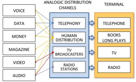
Before content digitization age, the different communication services available formed a chain of discrete components that restricts different content types to specific networks and terminals. In many cases, as for example in telephony, the service provider company was vertically integrated through-out the production chain. This production chain (Fig. 1) did not permit information transfer from one service to an-other. One example was the use of a telephone service on a TV show to allow the viewer participation. This integration could only exist through the use of human components in the TV show production.
Content digitizing allowed its storage and distribution in many telecommunications systems. This fact coupled with technological innovation of telecommunications networks
has increased the digital convergence phenomenon. Digital TV emergence is another advance that confirms the increase of this fact. Two main consequences of digital convergence can be highlighted:
1. The possibility to access the same content on different platforms (TV, Smartphone, PC, and so on) and also; 2. The functional overlap use of different networks and
ter-minals (e.g., using Internet to talk on the phone or using TV to access Internet).
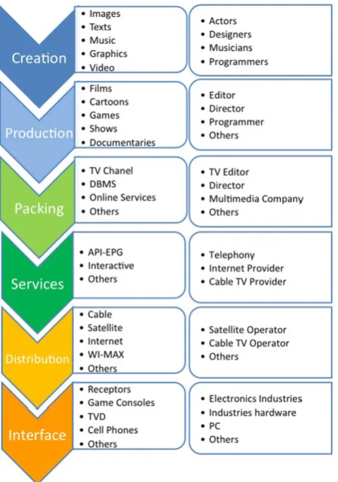
Thus, it is possible to say that the old vertical segmenta-tion chain was replaced by a new a convergent digital model composed of six distinct segments (Creation, Production, Packing, Services, Distribution, and Interfaces) as shown in Fig.2.
Figure 2 illustrates that there are software parts in the whole production chain. In Digital TV context, this new chain creates the possibility to introduce interactive ele-ments on a TV show using software components (iTV ser-vices), and as a consequence, will certainly change the way to design and produce these shows.
Fig. 2 New production chain
2.2 iTV software production
Digital TV represents a greater possibility of democratiza-tion in content generademocratiza-tion and distribudemocratiza-tion. This can be ob-served in the potential increase of channels number, in the opportunity to suite program content for a specific context (e.g., viewer, receiver, region), in providing interactive pro-grams (iTV) and so on.
In computational terms, an iTV show is a software, specifically a multimedia application, through which a viewer can interact via remote control [16]. It means that a viewer can receive from broadcaster, in addition to au-dio/video main streams, a software that allows him to inter-act with the presented content.
According to [10], iTV software applications may be di-vided into three groups:
1. Applications that have no relation with the semantic con-tent of audio and video presented e.g., E-mail and TV-banking
2. Applications that have a relation with the semantic con-tent of audio and video presented, but without strength synchronization restrictions, e.g., the shares price dis-played during a financial TV show and;
3. Applications that have a relation with the semantic con-tent of audio and video presented and that are displayed on a synchronized way, as for example: interactive Adds of products displayed in specific moments of a film.
This third applications group may be further subdi-vided into two subgroups:
(a) Applications with object content known in advance and;
(b) Applications with live generated content
The building process for software that belongs to the first category does not differ from traditional process. In this way, the only difference between iTV software and traditional software is the treatment of nonfunctional requisites such as, “ execution platform” (TV), “input and output mechanisms” (remote control), and so on.
Moreover, the building process for software that belongs to other categories is prepared in order to achieve some de-tails of TV environment. These fine points directly influence the production process and, therefore, these two categories should receive special treatment from designers. Among these fine points, it is possible to highlight:
1. The software is part of traditional TV show, which has its own format and context.
2. They use a TV receiver as the only interface, which is traditionally used in a collective way.
3. They require specific transmission infrastructure and software/hardware components for proper operation. 4. They change traditional TV shows in a way to enable
(a) Different levels of interactivity and (b) A nonlinear content organization.
A specific production process for interactive TV software should not only consider these fine points, but also provide an exclusive support for each one of them. The problem is that this process is not usual to TV industry, which has no culture of software development, and also is not usual to software industry, which has no culture of developing mul-timedia content for TV.
The research proposed in [22] addresses, specifically, the conceptual stages of modeling iTV applications. It presents a model for developing iTV programs, based on agile methodologies, which includes activities related to TV production process and software development. The model is outlined in four aspects: Work philosophy, Process, Roles/Responsibilities, and Artifacts.
The definition of work methodology is very important on both modeling and implementing process. Indeed, this process should have well-defined phases and cycles with details of activities that must be undertaken. The profile de-scription of involved human resources (programmer, test en-gineer, consultant, writer, director, and so on) as well as the responsibility of each one within the defined activities avoid distortions during model implementation and allow the en-tire team to construct, collaboratively, an iTV program. The end of each activity results in the production of artifacts (documents, codes, media, and submodels generated during the process) among which we can highlight: storyboards, timeline, interactivity flow, and interface rough (draft) to be implemented.
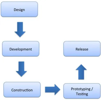
The model divides the life cycle of iTV software devel-opment in 5 short phases (Fig.3), with continuous iterations and tight integration between users (viewer) and develop-ment team. These phases are:
Fig. 3 Life cycle of iTV software development
1. Design 2. Development 3. Construction
4. Prototyping/Testing and 5. Release
The main objective of design stage is the awareness of opportunity to create an iTV program. This step defines what iTV content will be presented to user/viewer. The most relevant activities of this stage are: (i) search for opportuni-ties, (ii) initial project creation, and (iii) test design. It is understood as (i) the use of methods (meetings, brainstorm-ing, and so on) to encourage the search for new business op-portunity and also the innovation of an existing program. In activity (ii) a storyboard, which represents the initial design with program central idea, services intentions and features to be offered to the user, is created. Activity (iii) is responsi-ble for validating the initial project. Participate in this stage, the producer, the creation manager, the writer (e.g., novel-ist), the project manager and the user/viewer.
The development phase tries to predict the many factors that may affect the development of iTV programs. Among the main activities of this phase, it is possible to mention: (i) planning, (ii) script creation, (iii) architectural design, and (iv) visual programming. Activity (i) consists of esti-mating programs schedule and cost, creating a release plan of program iterations, defining the roles of each work team as well as recruit involved professionals. It is understood as (ii) the textual description of the program with information that shows special needs of interactive application (e.g., use of interactive channel, database, outsourcing services, and so on). This artifact can be compared to the requisite docu-ment and, as such, may undergo several revisions until the release of an iTV program. Activity (iii) consists of creat-ing an architectural design to describe exactly what should be built on the application as a whole (e.g., software, inter-activity level, media elements, and so on). The architectural design should contain complete information about the sys-tem (middleware) to be used, the interactivity level of an iTV program, the required functionalities, the existing infrastruc-ture, and security design. Finally, activity (iv) includes the creation of graphics and visual elements to be presented in an iTV program. All staff participates in this phase.
the modules that compose the software. Some practices, in-herited from the agile methodologies, are adopted here to prevent that failures in software implementation disturbs the TV show. The life cycle of the production process for con-ventional TV show is represented by activity (iii). Finally, activity (iv) represents the integration of software and en-coded medias. The team of graphic design and software as well as publishers and producers are the main participants in this phase.
Some remarks should be highlighted on the construction phase, specifically on coding activity of the software that may be part of an iTV show. This activity can be structured through synchronized compositions of nodes that represent encoded medias (video, audio, text, images, data, compo-nents, and software services). However, a perfect conception of an iTV show should be different from the way that tra-ditional hypermedia/multimedia presentations are designed. The design of an iTV show must consider requisites that are specific to the TV environment as described above.
The implementation an iTV program can be done through two paradigms: declarative and procedural. In procedural programming, the programmer encodes each step to be exe-cuted by the execution machine, which is done through the algorithmic decomposition of a problem. The advantage of this paradigm is the largest code control exercised by the programmers, which allows establishing all the control and execution flow of a program. Among the most common cedural languages available for implementing a iTV pro-gram, it is possible to highlight: Lua [13], Java [6], EC-MAScript [9]. In declarative paradigm, the programmer pro-vides the set of tasks to be performed at a higher abstraction level that does not consider details of how these tasks are actually performed. In other words, the language empha-sizes the descriptive statement of a problem rather than its decomposition in algorithmic implementations [20]. Some examples of declarative languages for iTV are: NCL [18] and XHTML [14].
The Prototyping/Testing phase is one of the most im-portant steps of the process. It occurs in parallel with the previous steps and the main participants in this step are the software engineer and producer. The activities performed in this phase are: prototyping, unit testing, integration testing, performance testing, usability testing, typing review, and in-frastructure testing.
The release occurs after the conclusion of all tests, indi-cating that the program is completed. When the iTV pro-gram is ready to be delivered, the producer is responsible for commercially promoting the program with potentially users/viewers.
Although the approach described above [22] is useful, since it allows defining the conceptual stages of modeling iTV applications, it is not focused on the structuring of soft-ware components in TV context, but on defining what are
the general activities of the production process and not how these activities should be performed. The following model, StoryToCode, allows to specify iTV programs focused on the use of software components. It focuses on development and construction stages and it main goal is to reuse these components in other contexts.
The StoryToCode is concentrated in activities that oc-cur after the design and development phases. These activ-ities can be grouped into two modules: activactiv-ities of me-dia production/generation (images, videos, texts, and so on) and activities of software producing. The StoryToCode deals specifically with the activities of the second module. The software project staff in collaboration with the entire TV crew is responsible for its implementation.
3 The StoryToCode model
The StoryToCode (proposed model in this paper) main ob-jective is to allow the specification and construction of soft-ware components for use in iTV programs and in other con-texts. For StoryToCode, the word context means the soft-ware execution platform (TV, Mobile, Web, and so on). The StoryToCode starting point is the storyboard. From this point, the model uses concepts of systems modeling to: (i) create a set of elements to represent both media and soft-ware components that compose an interactive program, and also (ii) highlight some systemic views (structure, events, and so on) in order to reuse the generated artifacts in other contexts. One of the advantages of using StoryToCode is the possibility to design software systems based on information extracted from storyboards. Since the storyboard is one of the most used artifact in the multidisciplinary atmosphere of a TV show, it was chosen as the starting point in Sto-ryToCode. In fact, the idea is that this model facilitates the work of the team, making it easier to understand and im-proving an application development process. Another ad-vantage, inherited from MDA, is the ability to generate dif-ferent views of the same software facilitating their reuse in other contexts.
The StoryToCode architecture is separated into three parts, which are connected to each other, as illustrated in Fig.4: storyboard, elements, and source code generation. Such an architecture is based on RoundTrip Engineering (RTE) [3] concept, and as consequence, it allows the bidi-rectional exchange between more abstract definitions (archi-tecture and design) and (possibly) the source code. In other words, it defines how the transformation of a storyboard into a set of abstract elements should be done and also illustrates the transformation of these elements in a source code. On the other hand, it also allows generating the elements from source code and after that generates the storyboard.
Fig. 4 StoryToCode architecture
3.1 Storyboard
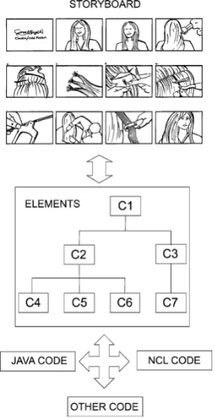
In an environment focused on generating content for iTV, a storyboard can be defined as a technique used to describe the basic sequence of scenes that best represent a TV show. This technique provides a high-level description of the ele-ments that compose each scene and the interactivity flows that arise during the software use. Although the storyboard can be considered an “informal” and “weakly structured” technique, it is used to model the presentation scenes flow (transition), the interactive effects and temporal narratives (e.g., dubbing, narration), scenes layout, and so on. The in-formation contained in a storyboard range from the list of scenes that compose the program through its draft visual-ization until the description of its contents (pictures, videos, text, graphics, animations, links [from→to]). Figure5 il-lustrates the structure of a possible storyboard. Such an ex-ample is also used to motivate the model adoption.
The problem of transforming a storyboard in a set of soft-ware elements is solved in the first part of StoryToCode. The model defines that the storyboard should be used, as a requi-site repository that must be met in order to construct a set of elements. In the current version model, this transformation is still a manual process (see Fig.6). Thus, the software project staff should use the storyboard (built at the design stage) to extract the requisites and generate an abstract representation
Fig. 5 Example of a storyboard frame
Fig. 6 A storyboard used as the repository of requisites
of all elements contained in the program scenes with their relations and interactive events. This set of elements repre-sents the second part of StoryToCode, and is presented in the following section.
3.2 Set of software elements
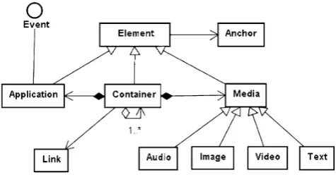
Fig. 7 StoryToCode elements hierarchy
storyboard. The StoryToCode elements hierarchy is similar to Nested Context Presentation Model (NCPM) [19] class hierarchy and can be seen in Fig. 7. To allow the specifi-cation and extension of elements in UML and also in XMI formats, the StoryToCode uses a framework named Eclipse Modeling Framework (EMF) [21] (see Fig.6).
At the root of StoryToCode hierarchy is the element “ El-ement,” whose main function is to serve as base model for creating other elements, pooling their common character-istics and behaviors. An Element is an entity that has the following attributes: a unique identifier, a descriptor (which contains the information to determine how an entity must be presented), and a list of anchors. An anchor is defined as a region (in time or space) used to mark contents of an element and to “tie” the links (Link). Anchors are represented in Sto-ryToCode by the elementAnchor. AnElementcan also be specialized in three entities: Media,Application,and Con-tainer.Mediaelements are those whose primary responsi-bility is to abstract medias during a presentation. AMedia element has attributes such as “content” and “anchors list” (inherited from Element), whose values definition are de-pendent on the dynamics of a specific program instance. The StoryToCode allows specializing aMediaelement in order to abstract the numerous media types covered in a story-board (e.g., video, image, text, and audio). TheApplication element in that hierarchy is used to define data structures of a software component, whose operations (instructions) are responsible for handling interactive events specified in a sto-ryboard. To do so, such an element needs to be specialized and each concrete element created from anApplication el-ement must meet theEventinterface. This interface should also be specialized to define what are interactivity events and how they should be treated. The focus of theEventand Applicationelements is to allow the representation of data structures typically found in software elements. These struc-tures can be directed to both business components as visual components. Thus, these software components can abstract storyboard elements and actions that arise from the use of each element, as for example, selecting buttons, displaying progress bars, displaying alerts, credit card operations, and
so on. Finally, theContaineris an element that represents a composition between Media and Application elements, whose cardinality is 1→N (one to many). It can be used to assembly storyboard elements ranging from menus, but-tons, and images, even the entire program scenes. To do so, aContainerhas as attributes: (i) a list of links between ele-ments (Link), responsible for defining a connection between an origin and a destination element, and (ii) another list of elementsContainer.
The approach used on StoryToCode model to treat soft-ware data structures represents an important difference be-tween NCPM and StoryToCode. The NCPM model does not clearly support the extension of data structures that abstract business components or even visual components. We assume that this could be done through the Script el-ement, defined in NCPM hierarchy. AScriptis an element whose function is to store a program written in any language and whose instructions (operations), when executed, gener-ate messages invoking the activation of presentation objects valid methods [19]. Thus, while a NCPMScriptis a non-extensible element with focus on the temporal/spatial (vi-sual) aspects of presentation objects, a StoryToCode Appli-cation element can be extended in order to better abstract both the visual interface as the business logic of an applica-tion.
The StoryToCode defines that each model element must be specialized to contain its own features list in order to properly abstract a storyboard. This ability to extend the model to make it adjustable to any specification regards both media as software components structuring. This capacity to describe each storyboard element in great detail is what al-lows the use of transformations to achieve a lower abstrac-tion level, which means in this model, to produce an appli-cation code for a specific context.
3.3 Code
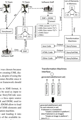
Once the elements collection is produced by the software staff and approved by the TV team, it is possible to reach the third StoryToCode stage: source code generation. This step consists of generating an application code for a specific context, using the set of generic elements generated in the previous step. For this, the StoryToCode defines a special component called transformation machine, which takes the elements collection as input and outputs the source code. Figure8shows the complete process dynamics of generating source code from storyboards on the StoryToCode model.
Fig. 8 The complete
StoryToCode process dynamics
made in UML. In fact, the XMI format was chosen because many frameworks and CASE tools allow creating UML dia-grams and exporting them to XMI. Thus, despite of using the EMF framework, the StoryToCode becomes flexible since it is possible to decide which CASE tool or framework should be used to create an element set.
After converting the set of elements to XMI format, it must be loaded into memory, and thus be used as input to a transformation machine. For this, the StoryToCode uses the JDOM library [12]. The JDOM is a Java open source API, which is based on standards SAX and DOM, used to manipulate XML documents. Thus, the JDOM allow to load into a DOM tree (in memory) the set of XMI elements and this tree is used as input to a transformation machine.
After receiving the input XMI file and loading it into memory, the software staff choose one of the available in-stances of transformation machine to generate code to a spe-cific platform. Each instance contains a set of transformation rules, based on the source (element set) knowledge, and a destination element structures (code for a specific platform). The transformation machine allows adding rules (and other important information) to enable mapping an element to a corresponding programming language source code. Thus, a transformation of a single element set can be made for dif-ferent platforms, since the transformation machine instance, which is specific to each of these platforms, is available.
Figure 9 illustrates the architecture of a transforma-tion machine. Each transformatransforma-tion machine concrete ele-ment (e.g., StoryToHTML, StoryToJava) must impleele-ment theTransformationMachineinterface, responsible for defin-ing thegenerateCodemethod and which receives as input
Fig. 9 Transformation machines architecture
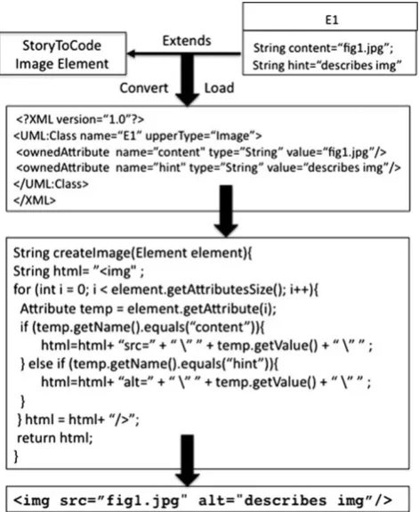
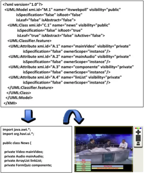
Figure10illustrates an example of a parse process where thegenerateCodemethod is used to generate a HTML im-age. Assume that E1 is part of the set of elements and that it is modeled as an extension of a StoryToCodeImagewith at-tributes: content (image file name) and hint (message that must appears when the image is selected). After convert-ing E1 to XMI and load it into memory, thegenerateCode calls the methodcreateImageusing E1 as a parameter. This method contains the rules that allow mapping E1Image ele-ment on a HTML image (img) tag. For this, the method uses a loop to go through and sort all the attributes of E1. Each attribute of E1 is mapped to the corresponding attribute in HTML:
1. content=“fig1.jpg” is mapped to src=“fig1.jpg” and
Fig. 10 Converting an Image Element to HTML image
2. hint =“describes img” is mapped to alt = “describes img”
The study case discussed in the next section shows a sum-mary of an experiment whose objective was to demonstrate the use of StoryToCode. In this experiment, two transforma-tion machine instances were implemented: one in TV con-text (JavaTV) and another on Web browser (HTML).
4 Case study
To show the viability of applying StoryToCode, a TV show (a fictitious newscast) was proposed. This show should con-tain an opinion poll to allow a viewer vote on different op-tions using the remote control or voting through Web. This opinion poll is a software component called ITVWebPoll (Interactive TV and Web Poll), which can be used in dif-ferent contexts (TV and Web).
In this show, the storyboard says that the viewer has the option of participating in an interactive opinion poll. This poll is structured into two scenes: “select option,” where the viewer can press the green button to see the opinion poll result, and “election,” which is presented when the viewer presses the yellow button. In “election” scene it is possible to vote through a menu. After each computed vote, the show presents the opinion poll partial result. Finally, if the viewer presses the red button, at any moment, the application will be terminated. The “election” scene description of this poll can be seen in Fig.5. The scenes flow to the program can be seen in Fig.11. In this flow, (1) indicates the automatic start, (2) that the viewer pressed the “view results” button, (3) that the viewer pressed the “Vote” button, (4) that the viewer se-lected one poll option and (5) that the viewer pressed the “Close” button.
The following functional requisites were extracted from the storyboard: (i) allow viewers to choose the options that suit them, without any restriction or limitation (all alter-natives should be treated in the same way), (ii) check the choice before confirming the vote, (iii) compute and execute an option chosen, (iv) show an alert to the viewers informing
Fig. 12 ITVWebPoll elements set
them that a vote has been computed, and (v) allow viewers to check results.
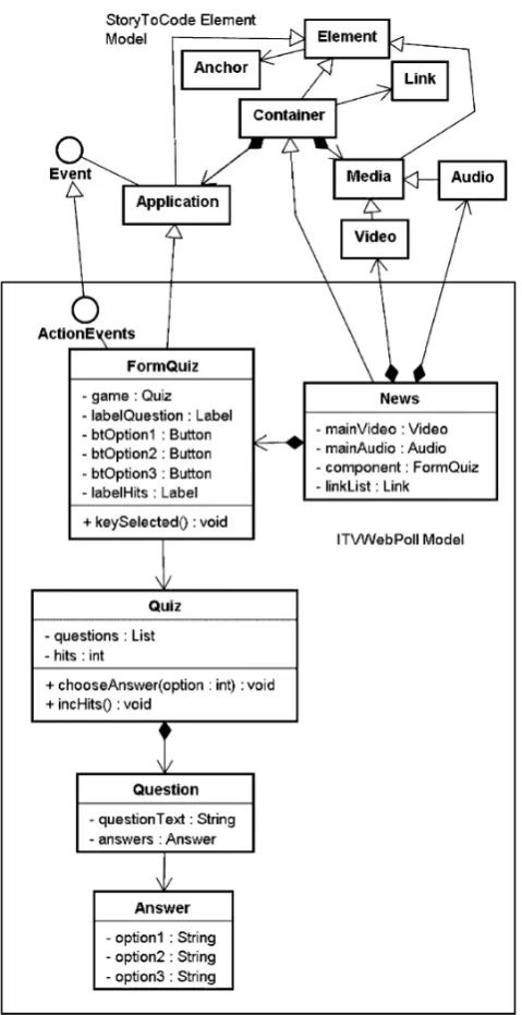
After the use of a storyboard to extract the list of func-tional requisites, it was possible to initiate the second part of StoryToCode: the creation of elements set for the ITVWebPoll. The elements set consist of:News, FormQuiz, Quiz, Question, and Answer beyond the interface Action-Eventsas can be seen in Fig.12.
TheQuiz, Question,andAnswerelements represent ab-stractions of a quiz business logic. Thus, aQuestionelement is an entity that has as main attributes the question text, and a list ofAnswerelements. EachAnswerelement has three at-tributes: two of them are false response options and the other
Fig. 13 From element set model to HTML and JavaTV
is a true one. Indeed, theQuizelement is a composition of questions (a list ofQuestionelements) and answers (Answer elements), whose main responsibility is to control the num-ber of hits (Question hitsattribute) achieved by a viewer. The FormQuizelement is a specialization of anApplicationthat abstracts the graphical interface used in the quiz. This in-terface includes two labels, responsible for displaying ques-tions and number of hits, and three buttons, which display the answer options. The main responsibility of this element is to treat the selecting one of the options event defined in the interfaceActionEventsthrough the methodkeySelected. In this method, at each time one of the radio buttons (the true option) is selected, and a hit is computed and displayed. At this point, the elements set still contains theNewselement, which is aContainerthat represents a composition of Au-dio,Video,FormQuizand a list of links (Link) required to synchronize the opinion poll elements.
Once the elements set has been defined, it was possible to start the third phase of StoryToCode. Two instances of transformation machine component have been implemented in order to make it possible to generate the ITVWebPoll source code either in TV and Web context: (i) elements set
→Java TV and (ii) elements set→HTML. These compo-nents receive as input a file in XMI format with ITVWebPoll elements. To produce this file, a CASE tool was used to convert the elements, written in UML format, into a file in XMI format. Based on the input elements file (XMI), both transformation machine components applied their rules to map elements from the source model to their target source code. Figure13illustrates some examples of mappings im-plemented in these rules.
The code generation of ITVWebPoll did not mean the end of codification work. The generated code in this StoryToCode stage represented a part of the definitive ITVWebPoll code. So, after this partial code has been gen-erated, the programming team still needed to complete the implementation work. Both planned transformations were implemented. Figure14 briefly shows the result of trans-forming a XMI file that represents theNewselement in its respective Java TV code.
5 Related work
Fig. 14 Code generation schema
a formal process in the development of software modules for such shows. Their focus is on only the construction of applications based on its visual structure. This can be seen, for example, in papers related to tools that support iTV ap-plication development.
The paper presented in [15] focuses on the development of highly interactive multimedia applications. In this re-search, an application is described as a multimedia appli-cation that typically provide a sophisticated user interface with integrated media objects. As a consequence, the de-velopment process involves different experts for software design, user interface design, and media design (the same approach is used in StoryToCode). There is still a lack of concepts for a structured development process to integrate these requirements. In this paper, the author introduces the Multimedia Modeling Language (MML), a visual modeling language supporting the design process in multimedia ap-plication development. It is part of a model-driven develop-ment approach for multimedia applications. The language is oriented on well-established software engineering concepts, in particular UML 2.0. It integrates the results of two differ-ent research lines: application-oridiffer-ented multimedia model-ing and model-based user interface development.
The paper presented in [5] focuses on the difficulties of people with little experience to learn and use, effectively, textual programming languages. The research indicates that visual programming tools may be useful to abstract the
com-plexity of such textual languages, minimizing the effort of specification. In this article, the authors present a visual ap-proach for specifying high level of spatiotemporal relations in documents Nested Context Language (NCL) [18]. The aim of this approach is to provide a visual intuitively rep-resentation to specify complex synchronization events be-tween medias.
The Composer [4] is a hypermedia authoring tool used in the encoding of interactive audiovisual program in NCL. Its main objective is to enable users to produce NCL code through visual abstractions. The hypothesis is that this ap-proach requires less specialized knowledge of NCL. To make this possible, the philosophy used by the composer is that the user who will build the program may do so through special views. It is important to highlight that these views do not represent the different levels of abstraction found in the MDA. There is no functionality to support the reuse of interactive modules generated in other contexts.
A similar description to Composer can be made to the NCL Eclipse plug-in [1]. It is an open source text editor for the NCL language integrated with the Eclipse environ-ment that also has focus on providing a tool (WYSIWYG approach) to support the generation of NCL source code. The plug-in also does not provide any functionality to sup-port the reuse of code or even the more abstract design specifications. Among the main features implemented by NCL Eclipse are: coloring XML elements and attributes, display/hide the XML elements (allowing certain elements to be hidden or displayed by the user), wizards to create sim-ple documents NCL, XML code autoformat and autocom-plete, NCL document validation, and so on.
Another plug-in associated with Eclipse, called SAGA, is presented by [17]. The SAGA is based on visual compo-nents which can be spatially arranged in the visual devel-opment environment. These components are extensions of specific libraries for iTV. The plug-in makes up a develop-ment environdevelop-ment and simulation for the Java language and aims to assist the coding of the modules to interactive digital TV programs for Ginga.
6 Conclusion
Also, it does not require a special knowledge in the systems modeling area from the participants of production process, born on the TV universe.
Despite StoryToCode prove to be adequate for the spec-ification and reuse of interactive components, it leaves two problems unresolved. The first one (P1) is associated with the extraction of requirements that are necessary for creating the set of elements. The second problem (P2) is the amount of rework required to complete the automatically generated code.
In the model, extracting the requirements from story-boards is one activity that is not automated. This activity is made solely by the team of software engineers. Automat-ing this process is still a challenge of very high computa-tional cost for computer science, because it means imple-menting aspects of human cognition in data recognition.The approach adopted in StoryToCode is traditionally used for designing systems and defines that the participation of pro-fessionals associated to the TV domain should occur only in the validation (approval) of the requirements specified (see Fig.8). This situation characterizes the P1 problem: To present the requirements in the form of a set of elements in UML hinders the understanding of TV professionals in the validation process. This causes misunderstandings between what the software engineers and TV professionals consider as a requirement for an interactive component.
The P2 problem is also associated with use of a set of elements to structure the requirements of an interactive pro-gram. In StoryToCode, it is not possible to insert instance information to the set of abstract elements generated in the second stage. The absence of this information comes as a consequence P2: increased workload to complete the gener-ated code. In StoryToCode, such information, which is es-sential in generating the code, are introduced by the pro-gramming team, after the partial generation of code for sub-sequent approval by the TV Team.
The next steps of this research include the creation of mechanisms to solve the P1 and P2 problems. This will be done through the creation of a new layer in StoryToCode. This layer will be inserted between the storyboard and the set of elements and will be built based on techniques of software prototyping to the design of interactive compo-nents. The main advantages of prototyping technique are: the closeness of the system with the needs of users, the re-duction of misunderstandings between users and develop-ers and also the reduction in development effort. Prototypes are concrete models and represent both the description of information structure as information instance that must be present in an application.
Acknowledgements This research was supported by CAPES (Project N. 23038.042785/2008-21) and FAPESB (PES0001 / 2007). The au-thors also acknowledge the participation of Flavia M.S. Nascimento who made an extensive review of this paper.
References
1. Azevedo GR, Teixeira MM, Soares Neto SC (2009) Ambiente integrado para o desenvolvimento de aplicaçes para TV digital interativa em nested context language. In: SBRC ’09: Simpósio Brasileiro de redes de computadores. SBC, pp 53–57
2. Brown AW (2000) Large-scale, component based development. Prentice Hall PTR, Upper Saddle River
3. Frankel D (2003) Model driven architecture: Applying MDA to enterprise computing. Wiley, New York
4. Guimaraes RL, Costa RMR, Soares LFG (2008) Composer: Au-thoring tool for iTV programs. In: EUROITV ’08: Proceedings of the 6th European conference on changing television environments. Springer, Berlin, pp 61–71
5. Guimaraes RL, Soares Neto CS, Soares LFG (2008) A visual ap-proach for modeling spatiotemporal relations. In: DocEng ’08: Proceeding of the eighth ACM symposium on document engineer-ing, New York, NY, USA. ACM, New York, pp 285–288 6. Jones J (2002) Dvb-mhp/java tv™data transport mechanisms. In:
CRPIT ’02: proceedings of the fortieth international conference on tools pacific, Darlinghurst, Australia, 2002. Australian Computer Society, Inc, Sydney, pp 115–121
7. Jung C-Y, Kim J-S, Yoo C-S, Kim Y-S (2006) Model of gener-ating smil document using temporal scripts of animation com-ponent. In: Computational science and its applications—ICCSA 2006. Springer, Berlin, pp 990–1000
8. Leite LEC, de Souza Filho GL, de Lemos Meira SR, de Arújo PCT, de Lima JFA, Filho SM (2006) A component model proposal for embedded systems and its use to add reconfiguration capabili-ties to the flextv middleware. In: WebMedia ’06. ACM, New York, pp 203–212
9. Lopez-Nataren C, Viso-Gurovich E (2005) An ecmascript com-piler for the .net framework. In: ENC ’05: Proceedings of the sixth Mexican international conference on computer science, Wash-ington, DC, USA, 2005. IEEE Computer Society, Los Alamitos, pp 235–239
10. Marques Neto MC, Santos CA (2008) An event-based model for interactive live tv shows. In: MM ’08: Proceeding of the 16th ACM international conference on multimedia, New York, NY, USA, 2008. ACM, New York, pp 845–848
11. Marques Neto MC, Santos CA (2009) Storytocode: Um mod-elo baseado em componentes para especificacao de aplicacoes de tv digital e interativa convergentes. In: WebMedia ’09: Simpósio Brasileiro de sistemas multimidia e Web, Porto Alegre, RS, Brazil, 2009. SBC, pp 59–66
12. Marques Neto MC, Passos C, Santos CA (2003) Tecnologias para Processamento de Documentos XML: Uma Abordagem JAVA. In: ERI ’03: III escola regional de informatica, Vitoria, ES, Brazil, 2003. SBC, pp 63–94
13. Mascarenhas F, Ierusalimschy R (2008) Efficient compilation of lua for the clr. In: SAC ’08: Proceedings of the 2008 ACM sym-posium on applied computing, New York, NY, USA, 2008. ACM, New York, pp 217–221
14. Pemberton S (2002) Xhtml 1.0: The extensible hypertext markup language, 2nd edn. World Wide Web Consortium, Recommenda-tion REC-xhtml1-20020801, August 2002
15. PleuB A (2005) MML: A language for modeling interactive multi-media applications. In: ISM ’05: Proceedings of the seventh IEEE international symposium on multimedia, Washington, DC, USA, 2005. IEEE, New York, pp 465–473
16. Rodrigues RF, Soares LF (2006) Produção de conteúdo declara-tivo para TV digital. In: SemiSH—XXXIII seminario integrado de software e hardware, Campo Grande, MS, Brazil, 2006. SBC, pp 287–300
interativas para TV digital baseado no middleware ginga. In: IX escola regional de computao Bahia—Alagoas-Sergipe, SBC, pp 1–6
18. Silva HVO, Rodrigues RF, Soares LFG, Muchaluat Saade DC (2004) Ncl 2.0: integrating new concepts to xml modular lan-guages. In: Symposium on document engineering ’04, New York, NY, USA, 2004. ACM, New York, pp 188–197
19. Soares LFG, Rodrigues RF, Saade DCM (2000) Modeling, author-ing and formattauthor-ing hypermedia documents in the hyperprop sys-tem. Multimed Syst 8(2):118–134
20. Soares LFG, Rodrigues RF, Moreno MF (2007) Ginga-ncl: the declarative environment of the Brazilian digital TV system. J Brazil Comput Soc 12:37–46
21. Steinberg D, Budinsky F, Paternostro M, Merks E, Gronback RC, Milinkovich M (2009) EMF: Eclipse modeling framework, 2nd edn. The eclipse series. Addison-Wesley, Upper Saddle River 22. Veiga EG, Tavares TA (2006) Um modelo de processo para o