ISSN: 2278-7461, www.ijeijournal.com
Volume 1, Issue 1(August 2012) PP: 01-10
1
A Design Space Exploration of Binary-Tree-Decoder For
Multi-Block- External-Memory-Controller in Multi-µc Embedded Soc
Design
Uday Arun
1, A. K. Sinha
21, 2Bharath Institute of Science & Technology, Chennai, Tamil Nadu, India
Abstract––In any Micro-Controller Embedded System the whole memory is accessed by a single Micro-Controller. It uses only a fraction of memory and rest of the memory is wasted. In addition to this the only one Micro-Controller is executing all the given set of instructions or program. In our work we have designed a Multi-Block external memory & Binary-Tree-Decoder for a Multi-Micro-Controller Embedded System so that the complete memory is divided into more than one block (in our case it is 4) and it can be accessed independently by more than one Micro-Controller. This can be done in two ways one is static memory mapping mechanisim and dynamic memory mechanisim. In static memory mapping, the Micro-Controller is able to access only a particular block of memory to which it is mapped. While in the Dynamic memory mapping, any Micro-Controller can access any block of memory. Also, the different part program is executed by different Micro-Controller parallely, which results in to speed up the execution speed of the Multi-Microcontroller system. Current embedded applications are migrating from single processor-based systems to intensive data communication requiring multi-processing systems to fulfill the real time application demands. The performance demanded by these applications requires the use of multiprocessor architecture. For these types of multiprocessor systems there is a need for developing such memory mapping mechanism which can support high speed. For selected memory mapping mechanism what should be the decoding mechanism and the controller design that gives low-power consumption, high-speed, low- area system. Our alorithtim of Binary-Tree-Decoder improves the MMSOPC embedded system design. However the designing of Binary-Tree-Binary-Tree-Decoder alorithim (for 256K memory) has not been designed by any of researcher which is presented in this work.
Keywords––SOC, MPSOC, MMSOC, MPSOPC
I.
INTRODUCTION
Current embedded applications are migrating from single processor-based systems to intensive data communication requiring multi-processing systems to fulfill the real time application demands.The performance demanded by these applications requires the use of multiprocessor architecture.For these type of multiprocessor systems there is a need for developing such memory mapping mechanism which can support high speed.For selected memory mapping mechanism what should be the decoding mechanism and the controller design that gives low power consumption, high speed , low area system. The designing of an on chip micro networks meeting the challenges of providing correct functionality and reliable operation of interacting system-on-chip components [1]. The dynamic partitioning of processing and memory resources in embedded MPSoC Architectures [3]. The idea of dynamic partitioning of memory resources is been used in designing the architecture of multi-block memory. The MPSoC design challenges, one of the key MPSoC architectural point while designing and programming is the memory access methods [20].
To acccess the multi-block memory we have used dynamic memory mapping technique and designed a controller for this external memory that is used in 8-bit Multi-MicroController-System-On-Chip[20][3].
In a multi-microcontroller SOCs there can be a possibility of two kind of memory mapping.
Static Memory mapping
Dynamic memory mapping
A. STATIC MEMORY MAPPING:
In static memory mapping, the micro-controller is able to access only a particular block of memory to which it is mapped.
Microcontroller No. Memory Block address Memory Block No.
MC01 0000-1FFF BLOCK0
MC02 2000-2FFF BLOCK1
MC03 3000-3FFF BLOCK2
2
Fig. 1 Static memory mappingB. DYNAMIC MEMORY MAPPING:
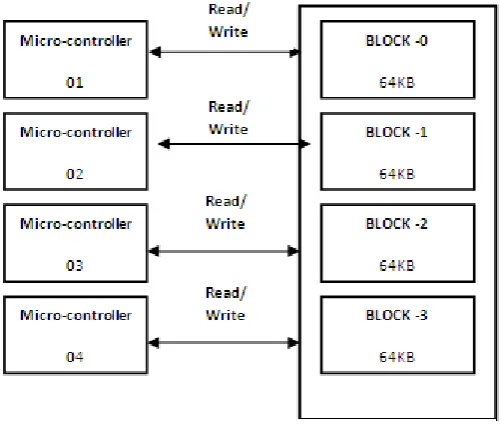
While in the Dynamic memory mapping any micro-controller can access any block of external memory, also the different program can be executed by different micro-controller parallely, which results in to high throuput & the performace of the multi-microcontroller system improves[19]. As Dynamic memory mapping gives more processing speed so we follow this technique[22]. But, this technique is very complex and requires extra hardware to implement this technique. An address decoding technique to generate memory address need to enchanced so that no extra burden on hardware.
Microcontroller No. Memory block No. Control signal Status
MC01 Block0,Block1,Block2,Block3 RD=0 & WR=1 READ
MC02 Block0,Block1,Block2,Block3 RD=0 & WR=1 READ
MC03 Block0,Block1,Block2,Block3 RD=0 & WR=1 READ
MC04 Block0,Block1,Block2,Block3 RD=0 & WR=1 READ
In the Dynamic memory mapping, any micro-controller can access any block of memory.
3
II.
MEMORIES
IN
MULTI-MICROCONTROLLER
ENVIRONMENT
There are different memory scheme available for SOCs having multiple Microcontrollers. Three of them are listed below[27].
UMA (Uniform Memory Access)
NUMA (Non-Uniform Memory Access)
COMA (Cache Only Memory Access)
CC-NUMA (Cache Coherency Non Uniform Memory Access)
CC-COMA (Cache Coherency Cache Only Memory Access)
A. UMA (Uniform Memory Access) Model:
Physical memory is uniformly shared by all the processors. All the processors have equal memory access time to all memory words, so it is called uniform memory access.
Each processor may use private cache.Multiprocessor are called tightly coupled systems, due to the high degree of resource sharing. The system interconnect takes the form of a common bus, crossbar switch or a multistage network. Synchronization and communication among processors are done through using Share variables in the common memory. When all the processors have equal access to all peripherals devices, the system is called a systematic multiprocessor. Here all the processors are equally capable of running the executive programs such as operatinsystem kernel and I/O service routines. When only one or subsets of processors are executive-capable, the system is called Asymmetric multiprocessor.
An executive or a master processor can execute the operating system and handle I/O. The remaining processors, having no I/O capability are called Attached Processors (APs) which execute codes under the supervision of the master processors.
B. NUMA (Non-Uniform Memory Access) Model:
NUMA multiprocessor is a shared-memory system where access time varies with the location of the memory word.
The shared memory is physically distributed to all processors, called local memory. The collection of local memories from a global address space is accessible by all processors. To access a local memory with a local processor is faster than to access the remote memory attached to other processors due to added array through the interconnection
Shared memory
Shared
Memory
P
1P
2P
nLM
1LM
24
network. Besides distributed memories, globally shared memory can be added to a multiprocessor system. In this case, there are three memory-access patterns:
(a) Local memory access (Fastest) (b) Global memory access.
(c) Remote memory access (slowest)
In hierarchically structured multiprocessors, Processors are devided into clusters which are itself an UMA or a NUMA multiprocessor.Clusters are connected to global shared-memory modules. All processors belonging to the same cluster are allowed to uniformly access the cluster shared-memory modules. All the clusters have equal access to the global memory.
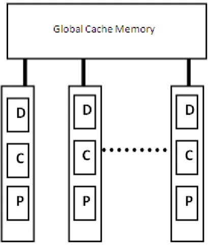
C. COMA (Cache Only Memory Access) Model:
A multiprocessor using cache-only memory assumes the COMA model.This model is a special case of a NUMA machine, in which the distributed main memoris are converted to caches.There, is no memory hierarchy at each processors node. All the caches memory is accessable from a global address space. Remote cache access is assisted by the distributed cache directories (D).
D. Other Model:
Another variation of multiprocessors is a cache-coherent non-uniform memory access (CC-NUMA) model
which is specified with distributed shared memory and cache directories.
One more variation may be a cache-coherent COMAmachine where all copies must be kept consistent.
5
III.
SOC
MODEL
AND
DESIGN
This is the generic system architecture of the Multi- microcontroller system on chip. In our project the multi block external memory is basically the integrated form of the following components:
1. MAR (Memory Address Register) 2. MDR (Memory Data Register)
3. MMBAC(Multi Memory Block Arbitration Controller)
4. BINARY TREE DECODER
5. Memory Block comparator 6. Memory of 256 Kb
In the above shown architecture the four microcontroller are connected to the memory via different controllers and buffer (register like MAR, MDR) with the help of address bus , data bus and control bus. Buses are nothing but the set of parallel wires that connect two components. In this architecture the data buses are of 8Bits, address buses are of 16Bits wide.
A. BINARY TREE DECODER
6
Fig.7. Decoding Mechanism of Binary Tree DecoderAfter Decoding Mechanism of Binary Tree Decoder, Binary Tree generation and memory address generation for all blocks of memroy follows an algortihm which is as follows:
for i in 0 to 255 loop
if conv_integer(BinaryTreeDecoder_En) = i then
--ForestTreeDecoder_Out := 16*i + conv_integer(y); ………..Old Algo. BinaryTreeDecoder_Out := 256*i + conv_integer(y); ………..……..New Algo.
B .RTL Schematic of Decoding Mechanism of Bianry Tree Decoder
Fig.8: RTL Schematic of Binary Tree Decoder (BTD)
EN7 EN6 EN5 EN4 EN3 EN2 EN1 EN0 A7 A6 A5 A4 A3 A2 A1 A0
0 0 0 0 0 0 0 0 0 0 0 0 0 0 0 0 0
0 0 0 0 0 0 0 0 0 0 0 0 0 0 0 1 1
0 0 0 0 0 0 0 0 0 0 0 0 0 0 1 0 2
0 0 0 0 0 0 0 0 0 0 0 0 0 0 1 1 3
0 0 0 0 0 0 0 0 0 0 0 0 0 1 0 0 4
. . . .
. . . .
. . . .
0 0 0 0 0 0 0 0 1 1 1 1 1 1 1 1 255
0 0 0 0 0 0 0 1 0 0 0 0 0 0 0 0 256
0 0 0 0 0 0 0 1 0 0 0 0 0 0 0 1 257
0 0 0 0 0 0 0 1 0 0 0 0 0 0 1 0 258
0 0 0 0 0 0 0 1 0 0 0 0 0 0 1 1 259
0 0 0 0 0 0 0 1 0 0 0 0 0 1 0 0 260
. . . .
. . . .
0 0 0 0 0 0 0 1 1 1 1 1 1 1 1 1 511
. . . .
. . . .
0 0 0 0 0 0 1 1 1 1 1 1 1 1 1 1 1023
. . . .
. . . .
1 1 1 1 1 1 1 1 1 1 1 1 1 1 1 1 65535
7
Fig.8: RTL schematic of integrated blockFig.9: RTL schematic of MULTI-BLOCK-EXTERNAL-Memory-Controller IN Multi-µC SOC DESIGN
C. Results
8
C.1. Design summary of Binary tree decoderC.2.Comperative Area Analysis of Binary Tree Decoder and Forest Tree Decoder
Sr. No.
Parameter
(64KB Memory Block)
Forest Tree Decoder Binary Tree Decoder Comments
1 No. of Decoder 4096 256 16times less than the
Forest Tree Decoder 2 Synthesis Time/Issues Unable to finish
synthesis, tool crashes due to requirement of large virtual memory space
Able to synthesize faster
9
C.3.Power Analysis of Binary Tree DecoderS.No. Performance metric (power)
Type Voltage
(V)
Current (mA)
Power (mW)
1 Vccint 1.8 15 27
2 Vcco33 3.3 2 6.6
Total Power 33.6
C.4. Results from X-Power summary report of the integrated design
Voltage Total Current Total Power
Vdd =3.3V, Vt =1.8V 17mA 33.6mW
IV.
CONCLUSION
Our result is tested, verified & prototped on the following environment using following Hardware & software tools & technology:
• Target Device: xc2s600e-6fg456
• On Board frequency: 50 MHz
• Test frequency: 12MHz
• Supply Voltage: 3.3 volts
• Worst Voltage: 1.4 to 1.6 volts
• Temperature: -40oC to 80oC
• Speed Grade: -6
• FPGA Compiler: Xilinx ISE 8.2i
• Simulator used: ModelSimXE-ii 5.7g
The initial implementation was based on forest tree decoder. The major enhancement done in this work is to replace Forest Tree Decoder with Area, power efficient implementation of Binary Tree Decoder. The decoding process is one of the most time consuming process, this decoding mechanism in turn makes the whole MPSOC system faster and efficient with help of multi block memory architecture. With reference to the 2d VLSI complexity model we have found that as x-axis (data lines) width is kept fixed (8 bit) and y-axis (row address of memory) height is reduced in case of binary tree decoder in comparison to forest tree decoder.So the over all area of 2D model is reduced which in turn increases the accessing speed of the multi-processor system. As the y-axis height is reduced this implies that searching time of particular memory word (8 bit here) is reduced hence accessing speed is increased. In another aspect, as the area is lesser and the power consumed is also lesser.
REFERENCES
Journals:
1. Benini,L. and De Micheli, G.,2002. Networks on Chips: A new SoC paradigm. IEEE Computer, 35(1), 2002; 70-78.
2. Beltrame,G.,Sciuto,D.,Silvano.C.,Paulin,P.and Bensoudane,E.,2006. An application mapping Methodology and case study for multi-processor on –chip architectures.Procceding of VLSI SoC 2006. 16-18 October 2006, Nice.France 146-151.
3. Xue, L.,Ozturk , O.,Li.F., Kandemir, M. and Kolcu. I.,2006.Dynamic partitioning of processing and memory resources in embedded MPSoC architectures .Proceeding of DATE 2006 ,6-10 March 2006, Munich,Germany, 690-695.
4. Benini,L. and De Micheli, G.,2006. Networks on Chips: Technology and tools. Morgan Kaufmann, San Francisco,2006,ISBN-10:0-12-370521-5.
5. Berens, F.,2004. Algorithm to system-on-chip design flow that leverages system studio and systemC 2.0.1. The Synopsys Verification Avenue Technical Bulletin 4,2,May 2004.
6. Bouchhima , A., Yoo, S. and Jerraya, A. A.,2004. Fast and accurate timed execution of high level embedded software using HW/SW interface simulation model. Proceeding of ASP-DAC 2004,January 2004, Yokohama,Japan,469-474.
7. Bouchhima, A.,Chen ,X.,Petrot, F.,Cesario, W.O. and Jerraya, A. A.,2005. A Unified HW/SW interface model discontinuities between HW and SW design .Proceeding of EMSOFT’05,18-22 september 2005,New Jersey,USA, 159-163.
8. Bouchhima, A.,Bacivarov, I.,Youssef,W.,Bonaciu, M. and Jerraya, A. A.,2005.Using abstract CPU subsystem simulation model for high level HW/SW architecture exploration.Proceeding of ASP-DAC 2005, Shanghai.China,969-972.
9. Coppola, M., Locatelli, R., Maruccia, G.,Pieralisi,L. and Scandurra, A. Spidergon,2004.
10
11. Flake, P. and Schirrmeister. F.,2007. MPSoS demands system level design automation.EDA Tech Forum,4(1),March 2007 ; 10-11.
12. Gauthier, L..Yoo. S. and Jerraya, A. A.2001. Automatic generation and targeting of application specific operating systems and embedded systems software.IEEE TCAD Journal,20, Nr. 11,November 2001.
13. Guerin,X., Popovici, K., Youssef, W.,Rousseau, F.and Jerraya, A.,2007. Flexible application software generation for heterogeneous multi-processor System-on-Chip. Proceeding of COMPSAC 2007.23-27 July 2007,Beijing, China.
14. Ha, S.,2007. Model-based programming environment of embedded software for MPSoC. Proceeding of ASP-DAC’07, 23-26 January 2007,Yokohamma, Japan, 330-335.
15. Kangas.T.,Kukkala. P.,Orsila,H. Salminen,E. , Hannikainen, M., Hamalainen, T.D.,Riihimaki,J. and Kuusilinna, K.,2006.UML-based multiprocessor SoC design framework.ACM Transactions on Embedded Computing Systems (TECS),5(2). 2006.281-320.
16. Kienhuis ,B.,Deprettere. Ed. F.,van der Wolf. P. and Vissers. K.A.,2002. A methodology to design programmable embedded systems – the Y- Chart approach .Lecture Notes in Computer Science. Volume 2268.Embedded Processor Design Challenges. Systems, Architechture.Modeling and Simulation –SAMOS 2002.Springer, 18-37.
17. Khugaut, W.,Gadke, H. and Gunzel, R. Train,2006. A virtual transaction layer architecture for TLM- based HW/SW codesign of synthesizable MPSoC. Proceedings of DATE 2006, 6-10 March 2006 .Munich, Germany.1318-1323.
18. Jerraya , A. and Wolf , W.,2005. Hardware-software interface codesign for embedded systems. Computer, 38(2), February 2005 ;63-69.
19. Jerraya , A., Bouchhima, A and Petrot, F.,2006. Programming models and HW/SW interfaces abstraction for Multi- Processor SoC. Proceeding of DAC 2006 .San Francisco.USA, 280-285.
20. Martin, G.,2006. Overview of the MPSoC design challenge. Proceeding of DAC 2006, 24-28 July 2006, San Francisco, USA, 274-279.
21. De Micheli, G., Ernst,R.and Wolf, W. Readings in hardware/Software Co-Design.Morgan KAudmann, 2002, ISDN 1558607021.
22. Popovici, K. and Jerraya ,A. Programming models for MPSoC.Chapter4 in Model Based Design of Heterogeneous Embedded Systems. Ed. CRC Press.2008.
23. Popovici,K.,Guerin, X., Rousseau, F., Paolucci, P.S. and Jerraya, A.,2008 Platform Based software design flow for heterogeneous MPSoC. ACM Jouranal: Transactions on Embedded Computing Systems (TECS),7(4),July 2008.
24. Pospiech, F.,2003.Hardware dependent Software (Hds).Multiprocessor SoC Aspects. An Introduction. MPSoC 2003. 7-11 July 2003. Chamonix. France.
25. Sarmento, A., Kriaa, L., Grasset, A., Youssef, W.,Bouchhima, A.,Rousseau,F., Cesario, W. and Jerraya, A. A.,2005. Service dependency graph, an efficient model for hardware/software interface modeling and generation for SoC design . Proceeding of CODES-ISSS 2005, New York, USA, 18-21 September 2005.
26. Schirmer, G.,Gertslauer, A. and Domer, R.,2008. Automatic generation of hardware dependent software for MPSoC from abstract specifications. Proceeding of ASP-DAC 2008, 21-24 January 2008, Seoul,Korea.
27. Van der Wolf, P. et al,2004. Design and programming of embedded multiprocessors: An interface-centric approach .Proceeding of CODES+ISSS 2004,Stockholm, Sweden, 206-217.
28. Bacivarov, I., Bouchhima, A.A.ChronoSym, 2005. A new approach for fast and accurate SoC cosimulation,
International Journal on Embedded Systems(IJES),1(1),;103-111.
29. Yoo.S. and Jerrara,A. A.,2003.. Introduction to hardware abstraction layers for SoC .Proceeding of DATE 2003, 3-7 March 2003, Munich. Germany, 336 -333-7.
30. Youssef, M., Yoo. S.,Sasongko, A., Paviot. Y.and Jerraya, A., 2004. Debugging HW/SW interface for MPSoC: Video Encode System Design Case Study. Proceedingof DAC 2004, 7-11 June 2004, San Diego ,USA,908-913.
Books:
1. Wolf and Jerraya, “MPSOC Design”, Springer
2. Marc Moonen, Francky Catthoor, “Algorithms and Parallel VLSI architectures-III, Elsevier.