Combined Antenna Diversity of Polarization Using New
Design of Pifa for X Band Applications
Zeyneb .Berkat
, Nouredine. Boukli Hacene
laborotary of telecommunication, Faculty of Technology , University Abou-Bekr Belkaid Tlemcen,13000, Algeria
Abstract
—
This paper describes the design and simulation of new combined antenna using a probe-fed Planar Inverted-F Antenna (PIFA) with rectangular patch in the same substrate operates from 9 GHz to 10.66GHz. The polarization diversity is realized by this structure, its becomes one of the most important techniques than can be used, the main reason for this conception is that the method does not require any extra bandwidth or physical separations between the antennas. The simulation allowed the characterization of the designed antenna and the computing of different antenna parameters like S11 parameters, resonant frequency, bandwidth, directivity . The combined element is analyzed and the simulation results are presented . The results are very interesting. Index Term— Pifa, axial ratio, Combined Antenna circular polarization, linear polarization, diversity of polarization.I. INTRODUCTION
In every wireless telecommunication system, antennas
are some of the most essential elements that characterize the system. Antennas are responsible for effective propagation of electromagnetic energy from transmitter to receiver through the wireless channel. Design and implementation of antennas varies from system to system, depending on the special characteristics of the antennas, such as spectrum occupancy, transmitting power level, directionality, etc. The optimum design of an antenna, to meet those characteristics, has become a great challenge, especially in new technologies [1]. The population of mobile communication systems is growing continuously. The increasing capacity issue is becoming critical because of the expansion of wireless services and the number of mobile subscribers. The methods to solve this issue include the use of dual band and polarization diversity mobile systems. Wide bandwidth, high isolation and low cross polarization are the normal requirements for mobile antenna systems[2].However while achieving multiband there could be performance degradation in the other aspects of the antenna like gain. One of the most effective ways to achieve high efficiency is to use a substrate material with a dielectric constant close to air[3].
The dielectric losses associated with the microstrip patch antennas are also set the achievable gain. Bands x (8.Ghz to 10.6 Hz) primarily used by the military. Used in radar applications including continuous-wave, pulsed, single-polarisation, dual- single-polarisation, diversity of polarization, synthetic aperture radar and phased arrays. X-band radar frequency sub-bands are used in civil, military and government institutions for weather monitoring, air traffic control, maritime vessel traffic control, defence tracking and vehicle speed detection for law enforcement[4].
Today, one of the major problems to solve in a communication between a portable unit and a base station is dealing with signal fading caused by the multi-path propagating environment. A solution consists in using some polarization or pattern-diversity technique at the terminal side of the wireless link by means of employing several antennas [5]. However, although these techniques can easily be theoretically described, implemented and controlled for a regular-sized antenna positioned over a large ground plane, the situation is somewhat different for several small antennas integrated within a communicating object[6,7].
The small devoted space for the antennas in a mobile phone or a PDA (polarization diversity antenna), the strong coupling between these radiating elements and the unintended coupling with nearby metallic components may drastically degrade the array capability. For example, pointing the main polarized beam in any wanted direction may be difficult or quite impossible to achieve[8].
II. ANTENNA CONFIGURATION AND ANALYSIS i. Antenna Geometry
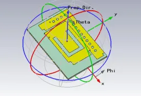
Fig. 1. Geometry of antenna combined
Inverted F Antenna (IFA) typically consists of a rectangular planar element located above a ground plane, a short circuiting plate or pin, and a feeding mechanism for the planar element. The Inverted F antenna is a variant of the monopole where the top section has been folded down so as to be parallel with the ground plane. This is done to reduce the height of the antenna, while maintaining a resonant trace length [9].
This parallel section introduces capacitance to the input impedance of the antenna, which is compensated by implementing a short-circuit stub. The stub’s end is connected to the ground plane through a via[10].
The ground plane of the antenna plays a significant role in its operation. Excitation of currents in the printed IFA causes excitation of currents in the ground plane. The resulting electromagnetic field is formed by the interaction of the IFA and an image of itself below the ground plane. Its behaviour as a perfect energy reflector is consistent only when the ground plane is infinite or very much larger in its dimensions than the monopole itself [11].
The resonant frequency of PIFA can be approximate with[11].
Fig. 2. Pifa structure
L1 + L2 = l/4 (1)
When W/L1=1 then L1 + H = l/4 (2)
When W=0 then L1 + L2 + H = l/4 (3)
Analysing the resonant frequency and the bandwidth characteristics of the antenna can be easily done by determining the site of the feed point, which the minimum reflection coefficient is to be obtained. Here, the idea of
antenna). Fig. 3 illustrates the transition structure. Coaxial cable is used for the antenna excitation.
(a)
(b)
Fig. 3.Geometry layout of antenna array (a), (b)
Present the set-up of simulation, with CST studio suite
a) Cut a slot on the top plane of PIFA to obtain the required multi band frequency
Fig. 4. Pifa with slot
b) Combined PIFA with micro strip to obtained PDA (polarization diversity antenna) characteristic.
Fig. 5. dimension of antenna combined.
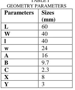
TABLE I GEOMETRY PARAMETERS
Parameters Sizes (mm) L 60
W 40
l 40
w 24
A 16
B 9.7
C 2.3
X 8
Y 3
The antenna combined polarization diversity considered for this investigation is to be designed on FR-4 substrate which has a relative permittivity
εr
of 4.4, a dielectric thickness h of 1.6 mm, a loss tangent of about 0.0010 and 0.035mm conductor thickness. Our new structure is designed to operate over the frequency range [9–10.66GHz] for X-band applications.Fig. 6. via hole dimension
The position and number of the via hole can be adjusted to find the optimal case when we used 15 via . Where d is via diameter and Y is the distance between the vias hole in this case d=1mm and Y=3mm . The following condition is required:
Y > 2d (4)
III. RESULTATS AND DISCUSSION
TABLE II
Main specification of the design
Parameters Specification (band X) F1 F2 F3
Frequency (Ghz)
9.4 9.75 10.25
S11<-10dB -15.4 -20.35 -24.75
Axial ratio (dB) 0.59<3dB 13>3dB 24.75>3 dB
Polarization Circular Linear Linear
VSWR <2 1.29 1.04 1.22
Size of antenna
60*40mm
ii. Reflection coefficients
Fig. 7. Simulated Reflection Coefficients (S11 in dB) of the Combined Antenna.
iii. Axial ratio
Fig. 8. axial ratio vs frequencies
Fig. 9. comparison with directivity in LHCP and RHCP at 9.4 GHZ
iv.VSWR
VSWR is plotted in Fig. 10. It is noted that lower reflection (VSWR<2).
Fig.10.VSWR vs frequencies
The two-element array is able to radiate different electromagnetic fields on purpose. Simulated and measured radiation patterns are presented for two phase differences. It is especially revealed that the novel structure is able to radiate
the same plane when changing the phase shift to 180°. Potential applications are polarization diversity technique.
Fig. 11. Coefficients of reflection with two phase differences
v. Directivity
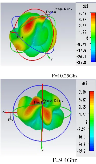
F=10.25Ghz
F=9.4Ghz
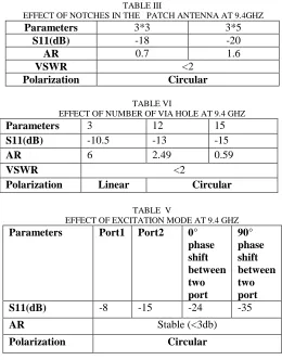
TABLE III
EFFECT OF NOTCHES IN THE PATCH ANTENNA AT 9.4GHZ
Parameters 3*3 3*5
S11(dB) -18 -20
AR 0.7 1.6
VSWR <2
Polarization Circular
TABLE VI
EFFECT OF NUMBER OF VIA HOLE AT 9.4 GHZ
Parameters 3 12 15
S11(dB) -10.5 -13 -15
AR 6 2.49 0.59
VSWR <2
Polarization Linear Circular
TABLE V
EFFECT OF EXCITATION MODE AT 9.4 GHZ
Parameters Port1 Port2 0° phase shift between two port 90° phase shift between two port S11(dB) -8 -15 -24 -35
AR Stable (<3db)
Polarization Circular
From table III and table IV, the results showed that the variation in the size of notches in the patch antenna does effect on all parameters , as shown the axial ration and return loss start to increase ,while for the AR is unstable when the size is increased , in table -5 as shown the stable axial ratio and s11 start to increase .
IV. CONCLUSION
In this paper, we described the design of a novel combined antenna with PDA characteristic able to radiate either circular or linear polarized electric fields in the azimuthal plane x bands exactly radar applications . The results of the array structure were simulated with CST which showed satisfying performance in terms of axial ratio and radiation patterns.
REFERENCES
[1] Giorgos TATSIS, Vasilis RAPTIS, Panos KOSTARAKIS “Design and Measurements of Ultra-Wideband Antenna”, Int'l J. of Communications, Network and System Sciences Vol.3 No.2(2010).
[2] Yujie Liu, Wei Tang, Yuehe Ge, Guogang Li “A Compact Wideband Dual-Polarized Printed Antenna with Coaxial Feeds for TD-SCDMA Application”, Wireless Engineering and Technology Vol.06 No.01(2015)
[3] Abbak, M , Karakus, C. ; Akduman, I..“A novel broadband and high gain antenna for GSM, UMTS, and LTE Wi-MAX applications “IEEE Transactions on Antennas and Propagation, 2010.
[4] Ming-Ju Tsai' and Nicolaos G. Alexopoulos “via hole modeling for an electromagnetically coupled patch antenna », IEEE.1994 .
[5] Tan Chee Sheng, Shaharin Anwar Sulaiman, Vinod Kumar “One-Dimensional Modeling of Hydrodynamicsin a Swirling Fluidized Bed”, IJMME-IJENS Vol:12 No:06.
[6] Ali Mehrdadian, and Keyvan Forooraghi* “design of a uwb combined antenna and an array of miniaturized elements with and without lens”, Progress In Electromagnetics Research C, Vol. 39, 37-48, 2013.
[7] Heba S.Mohammad, Heba A. Shawkey, and Adel Ezzat – ELHennawy “130 nm Flat Gain LNA for 6 - 9 GHz UWB Applications”, International Journal of Engineering & Technology IJET-IJENS Vol:14 No:06.
[8] Ayman Ayd R. Saad, Deena A. Salem, and Elsayed Esam M. Khaled "Band-notched UWB Annular Slot Antenna with Enhanced Bandwidth by using EBG Via Holes" International Journal Of Communications, Issue 3, Volume 7, 2013. [9] Gijo Augustin, Bybi P. Chacko and Tayeb A. Denidni
"A zero-Inde Metamaterial Unit Cell for Antenna Gain Enhancement" Antennas and Propagation Society International Symposium (APSURSI), 2013 IEEE pp.126- 127 July. 2013.
[10] Iulia Andreea Mocanu, Teodor Petrescu “Novel Dual Band Hybrid Rat- Race Coupler with CRLH and D-CRLH Transmission Lines”, Proceedings of the Asia- Pacific Microwave Conference 2011.
[11] R. Sanchez-Montero, S. Salcedo-Sanz and J. A. Portilla- Figueras, R. J. Langley “Hybrid Pifa- Patch Antenna Optimized B Evolutionary Programming” Progress In Electromagnetics Research, Vol. 108, 221-234, 2010. [12] S.Sai bharathwaj , K.prakash ,”Circular Polarization Dual Feed
Microstrip Patch Antenna With 3dB Hybrid Coupler For Wlan (2.4 GHz), International Journal of Engineering Science Invention, Volume2 Issue 9, pp.39-44, 2013. [13] Y.-Q. Zhang*, X. Li, L. Yang, and S.-X. Gong “dual-
band circularly polarized antenna with low wide- angle axial-ratio for tri band GPS applications”, progress in electromagnetics research c, vol. 32, 167-179, 2012. [14] Bybi P. Chacko, Gijo Augustin, Tayeb A. Denidni