JETIR1902975 Journal of Emerging Technologies and Innovative Research (JETIR) www.jetir.org 594
Design and Analysis of Lifting Hook with Different
Materials
1Pappuri Hazarathaiah, 2K.Venkateswarlu, 3M.Sreenivasulu 1Assistant Professor, 2Assistant Professor, 3Professor
1Mechanical Engineering,
1N.B.K.R.Institute of Science and Technology, Vidyanagar-524413, India
Abstract: The design of the hook is done by analytical method and design is done for the different materials like forged steel and high tensile steel. After the analytical method design and modeling of hook is done in modeling soft-ware (UNIGRAPHICS). The modeling is done using the design calculation from the modeling the analysis of hook is done in FEA software (HY-PERMESH).This result lead us to the determination of stress in existing model. By predicting the stress concentration area, the hook working life increase and re-duce the failure stress.
Keywords- Crane Hook and Finite Element Analysis (FEA)
I.INTRODUCTION
Crane hooks are the components which are generally used to elevate the heavy load in industries and constructional sites. Recently, excavators having a crane-hook are widely used in construction work sites. One reason is that such an excavator is convenient since they can perform the conventional digging tasks as well as the suspension works. Another reason is that there are work sites where the crane trucks for suspension work are not available because of the narrowness of the site. In general an excavator has superior maneuverability than a crane truck. However, there are cases that the crane-hooks are damaged during some kind of suspension works. From the view point of safety, such damage must be prevented. Identification of the reason of the damage is one of the key points toward the safety improvement. If a crack is developed in the crane hook, mainly at stress concentration areas, it can cause fracture of the hook and lead to serious accidents. In ductile fracture, the crack propagates continuously and is more easily detectable and hence preferred over brittle fracture. In brittle fracture, there is sudden propagation of the crack and the hook fails suddenly.
A lifting hook is a device for grabbing and lifting loads by means of a device such as a hoist or crane. A lifting hook is usually equipped with a safety latch to prevent the disengagement of the lifting wire rope sling, chain or rope to which the load is attached. A hook may have one or more built-in pulleys to amplify the lifting force. In 2009 Elebia presented the auto hook, a completely new concept of lifting hook. This automatic crane hook generates a magnetic field that attracts and guides the ring or the sling. The user presses a button on the remote control and the crane hook closes automatically.
A hoist is a device used for lifting or lowering a load by means of a drum or lift-wheel around which rope or chain wraps. It may be manually operated, electrically or pneumatically driven and may use chain, fiber or wire rope as its lifting medium. The load is attached to the hoist by means of a lifting hook.
The basic hoist has two important characteristics to define it: Lifting medium and power type. The lifting medium is either wire rope, wrapped around a drum, or load-chain, raised by a pulley with a special profile to engage the chain. The power can be provided by different means. Common means are hydraulics, electrical and air driven motors. Both the wire rope hoist and chain hoist have been in common use since the 1800s, however mass production of an electric hoist did not start until the early 1900s and was first adapted by Germany.
A hoist can be built as one integral-package unit, designed for cost-effective purchasing and moderate use, or it can be built as a built-up custom unit, designed for durability and performance. The built-up hoist will be much more expensive, but will also be easier to repair and more durable. Package units were once regarded as being designed for light to mod-erate usage, but since the 60s this has changed. Built-up units are designed for heavy to severe service, but over the years that market has decreased in size since the advent of the more durable packaged hoist. A machine shop or fabricating shop will use an integral-package hoist, while a Steel Mill or NASA would use a built-up unit to meet durability, performance, and repairability requirements. NASA has also seen a change in the use of package hoists. The NASA Astronaut training pool, for example, utilizes cranes with packaged hoists.
JETIR1902975 Journal of Emerging Technologies and Innovative Research (JETIR) www.jetir.org 595 manufacturing process, until it leaves a factory as a finished product, metal is handled by an overhead crane. Raw materials are poured into a furnace by crane, hot metal is then rolled to specific thickness and tempered or annealed, and then stored by an overhead crane for cooling, the finished coils are lifted and loaded onto trucks and trains by overhead crane, and the fabricator or stamper uses an overhead crane to handle the steel in his factory. The automobile industry uses overhead cranes to handle raw materials. Smaller work station cranes, such as jib cranes or gantry cranes, handle lighter loads in a work area, such as CNC mill or saw.
Almost all paper mills use bridge cranes for regular main-tenance needing removal of heavy press rolls and other equip-ment. The bridge cranes are used in the initial construction of paper machines because they make it easier to install the heavy cast iron paper drying drums and other massive equipment, some weighing as much as 70 tons. In many instances the cost of a bridge crane can be largely offset with savings from not renting mobile cranes in the construction of a facility that uses a lot of heavy process equipment. While sharing major components, overhead cranes are man-ufactured in a number of configurations based on applications.
EOT (Electric Overhead Traveling) Crane
This is most common type of overhead crane, found in most factories. As obvious from name, these cranes are electrically operated by a control pendant, radio/IR remote pendant or from an operator cabin attached with the crane itselfs.
Over head crane
This type of overhead crane has one end of the bridge mounted on a fixed pivot and the other end carried on an annular track; the bridge traverses the circular area beneath. This offers improvement over a jib crane by making possible a longer reach and eliminating lateral strains on the building walls.
II.LITERATURE REVIEW
Crane hooks are highly liable components [1] and are always subjected to failure due to accumulation of large amount of stresses which can eventually lead to its failure. To study the stress pattern of crane hook in its loaded condition, a solid model of crane hook is prepared with the help of ANSYS 14 workbench. Real time pattern of stress concentration in 3D model of crane hook is obtained. Finite Element Analyses have been performed on various models of crane hook having triangular, rectangular, circular and trapezoidal cross sections.
Strain aging embrittlement [1] due to continuous loading and unloading changes the microstructure. Bending stresses combined with tensile stresses, weakening of hook due to wear, plastic deformation due to overloading, and excessive thermal stresses are some of the other reasons for failure. Hence continuous use of crane hooks may increase the magnitude of these stresses and eventually result in failure of the hook.[2] All the above mentioned failures may be prevented if the stress concentration areas are well predicted and some design modification to reduce the stresses in these areas.
Bhupender Singh [3] worked on the solid modeling and finite element analysis of crane boom has been done using PRO/E WILDFIRE 2.0 and ALTAIR HYPER MESH with OPTISTRUCT 8.0 SOLVER Software to get the variation of stress and displacement in the various parts of the crane boom and possible actions are taken to avoid the high stress level and displacement. There are lot of applications of crane in industries and our daily life also. As it is a material handling machine, it is used for lifting loads and moves it from one place to another. In case of telescopic crane the whole weight/load is carried by its boom. Now a days, these types of cranes are commonly used due to less manufacturing cost, less space required and load can be lifted up to a maximum height very easily.
Y.Torres [4] worked to identify the causes that led to a failure of the crane hook in service. The study of the accident includes: (1) A summary and analysis of the peculiarities inherent to the standards that determine the manufacture and use of this type of device,
(2) Metallographic, chemical and fractographic analyses.
(3) Assessment of the steel mechanical behaviour in terms of Vickers hardness profile, its tensile strength and fracture energy (4). Simulation of the thermal history of the hook. The visual and microstructural inspections reveal some evidences that a weld bed was deposited on the hook surface. Several cracks grew from that area into the material. Fracture surface shows features typical of brittle failures (transgranular cleavage fracture). The unalloyed, low-carbon steel contains a relatively low aluminium (0.025 percent) and high non-combined ni-trogen (0.0075 percent) content. All the gathered evidences are in agreement with a strain-aging process triggering the embrittlement of the material, with the fracture starting from a crack generated at the heat affected zone of an uncontrolled welding of the hook.
JETIR1902975 Journal of Emerging Technologies and Innovative Research (JETIR) www.jetir.org 596 design are provided. Which supplies the clear direction for the improvement of the weak structure-strength. Key words: Hook, FEM, Statics 1
Bernard Ross [6] The catastrophic collapse of Big Blue on the Milwaukee Brewers baseball stadium retractable roof project could be the most awesome lift accident of all time. The crane, a Lampson TransiLift III with a 340 ft main boom and a 200 ft jib, was setting a 100 180 16 ft open truss panel roof section weighing close to 500 tons at a lift height of 230 ft. With 11 diesel engines, 6 miles of wire rope and 1150 ton counter weight, the 2100 ton crane was a massive machine, indeed The accident occurred during 26 mph average winds with gusts in the mid 30s. Three iron worker fatalities and hundreds-of-million dollar damages resulted from this mishap. The ensuing litigation pitted co-defendants Mitsubishi Heavy Industries, the crane lessee/operator versus Lampson, the crane designer/builder, on totally disparate theories for cause and origin of the failure
III.
F
INITEE
LEMENTA
NALYSISFinite Element Analysis (FEA) was first developed in 1943 by R. Courant, who utilized the Ritz method of numerical analysis and minimization of variational calculus to obtain approximate solutions to vibration systems. Shortly thereafter, a paper published in 1956 by M. J. Turner, R. W. Clough, H. C. Martin, and L. J. Topp established a broader definition of numerical analysis. The paper centered on the ”stiffness and deflection of complex structures”.
By the early 70’s, FEA was limited to expensive mainframe computers generally owned by the aeronautics, automotive, defense, and nuclear industries. Since the rapid decline in the cost of computers and the phenomenal increase in computing power, FEA has been developed to an incredible precision. Present day supercomputers are now able to produce accurate results for all kinds of parameters.
The finite element is a mathematical method for solving ordinary and partial differential equations. Because it is a numerical method, it has the ability to solve complex problems that can be represented in differential equation form. As these types of equations occur naturally. In virtually all fields of the physical sciences, the applications of the Finite element method are limitless as regards the solution of practical.
Design Problems
Due to the high cost of computing power of years gone by, FEA has a history of being used to solve complex and cost crit-ical problems. Classical methods alone usually cannot provide adequate information to determine the safe working limits of a major civil engineering construction or an Automobile or a Nuclear reactor failed catastrophically the economic and social costs would be unacceptably high.
In recent years, FEA has been used almost universally to solve structural engineering problems. One discipline that has relied heavily on this technology is the Automotive and Aerospace industry. Due to the need to meet the extreme demands for faster, stronger, efficient and light weight Au-tomobiles and Aircrafts, manufactures have to rely on the Technique to stay components and the high media coverage that the Industry is exposed to, Automotive and Aircraft companies need to ensure that none of their components fail, that is to cease providing the Service that the design intended.
FEA has been used routinely in high volume production and manufacturing Industries for many years. As to get a product design wrong would be detrimental. For example, if a large manufacturer had to recall one model alone due to a piston design fault. They would end up having to replace up to 10 million pistons. Similarly, if an oil platform Had to shut down due to one of the major components failing ( platform Frame, turrets, etc), the cost of lost revenue is far greater than the cost of fixing or replacing the components, not to mention the huge environmental and safety costs that such an incident could occur.
The Philosophy of FEA can be explained with a small example such as measuring the perimeter of a circle. If one needs to evaluate the perimeter of the circle without using the conventional formula, one of the approaches could be to divide the above circle into a number of equal segments. Join the beginning and end points of these segments by a straight line. Since it is very easy to measure the length of a straight line, the length of each line multiplied by the number of lines gives the perimeter of the circle. The same philosophy applies to FEA as well and we shall observe the same as we progress.
Finite element analysis was first developed for use in the aerospace and nuclear industries where the safety of structures is critical. Today, the growth in usage of the method is directly attributable to the rapid advances in computer technology in recent years. As a result commercial finite element packages exist that are capable of solving the most sophisticated prob-lems. Not just in structural analysis, but for a wide range of phenomena such as steady state and dynamic temperature distributions, fluid flow and manufacturing processes such as injection moulding and metal forming.
FEA consists of a computer model of a material or design that is loaded and analysed for specific results. It is used in new product Design, and existing product refinement. A Design Engineer shall be able to verify a proposed design, which is intended to meet the customer specifications prior to manufacturing or construction. Things such as, modifying the design of an existing product or structure in order to qualify the product or structure for a new serviced condition. Can also be accomplished in case of structural failure, FEA may be used to help determine the design modifications to meet the new condition
IV. RESULTS AND CONCLUSION
JETIR1902975 Journal of Emerging Technologies and Innovative Research (JETIR) www.jetir.org 597
Material
Young’s modulus(MPa)
Density(ton/mm
3)
Poisson’s
ratio
Forged Steel
1.2e5
7.9e-9
0.3
Wrought Iron
1.9e5
7.7e-9
0.3
Aluminum Alloy
7.5e4
2.8e-9
0.33
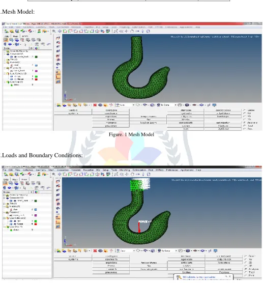
B.
Mesh Model:
Figure. 1 Mesh Model
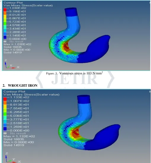
C.
Loads and Boundary Conditions:
Figure. 2 Loads and Boundary Conditions
JETIR1902975 Journal of Emerging Technologies and Innovative Research (JETIR) www.jetir.org 598 Figure. 3.
Vonmises stress is 103 N/mm
22.
WROUGHT IRON
Figure. 4. Vonmises stress is 113 N/mm
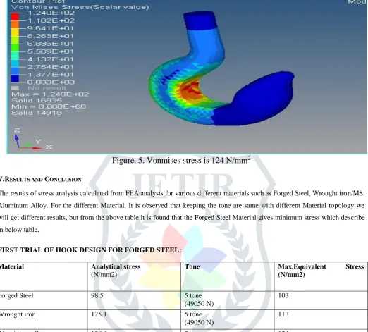
2JETIR1902975 Journal of Emerging Technologies and Innovative Research (JETIR) www.jetir.org 599
Figure. 5. Vonmises stress is 124 N/mm
2V.RESULTS AND CONCLUSION
The results of stress analysis calculated from FEA analysis for various different materials such as Forged Steel, Wrought iron/MS, Aluminum Alloy. For the different Material, It is observed that keeping the tone are same with different Material topology we will get different results, but from the above table it is found that the Forged Steel Material gives minimum stress which describe in below table.
FIRST TRIAL OF HOOK DESIGN FOR FORGED STEEL:
Material Analytical stress (N/mm2)
Tone Max.Equivalent Stress
(N/mm2)
Forged Steel 98.5 5 tone
(49050 N)
103
Wrought iron 125.1 5 tone
(49050 N)
113
Aluminium alloy 128.6 5 tone
(49050 N)
124
V. ACKNOWLEDGMENT
I sincerely express gratitude to my supervisor Prof. M.Sreenivasulu for his guidance, invaluable input , generous help , suggestions and inspiration in all stages of my work. I was introduced about very interesting topic of Design and Analysis of Crane Hook, which is of high practical importance in Automobile sector. His intellectual abilities have always rescued me in the difficult situations. It would not have been possible for me to complete this thesis without the guidance and support of him.
REFERENCES
[1] P. UDAY, S. J. REDDY, and G. SWAMYNADAN, “Finite element design and analysis of crane hook of crane hook with different cross sections,” 2015 [2] C. N. Benkar and D. N. Wankhade, “Finite element stress analysis of crane hook with different cross sections,” International
Journal For Technological Research In Engineering, vol. 1, no. 9, pp. 868–872, 2014
[3] B. Singh, B. Nagar, B. Kadam, and A. Kumar, “Modeling and finite element analysis of crane boom,” International Journal of Advanced Engineering Research and Studies, vol. 3, no. 2, pp. 306–309, 2011
[4] Y. Torres, J. Gallardo, J. Dominguez, et al., “Brittle fracture of a crane hook,” Engineering Failure Analysis, vol. 17, no. 1, pp. 38–47, 2010”
[5] Y. Huali and H. Xieqing, “Structure-strength of hook with ultimate load by finite element method “