© 2017 AJAST All rights reserved. www.ajast.net
Optimal Reactive Power Dispatch Using Chaotic Krill Herd Algorithm
R.Viola
1and A.Subramanian
21UG Scholar, Department of EEE, IFET College of Engineering, Villupuram, Tamilnadu, India. 2Professor, Department of EEE, IFET College of Engineering, Villupuram, Tamilnadu, India.
Article Received: 15 April 2017 Article Accepted: 25 April 2017 Article Published: 30 April 2017
1.INTRODUCTION
Power generation and transmission is a complex process, requiring the working of many of the power system in tandem to maximize the output. One of the main components to form a major part is the reactive power in the system. It is required to maintain the voltage deliver reactive power through the lines. Loads like motor load and other require power for their operation. To improve the performance of ac power systems, we need to manage the reactive power in an efficient way and this is known as reactive power compensation.
Need for Reactive Power Control
The main reason for reactive power control in system is: 1. The voltage regulation
2. Increased system stability
3. Better utilization of machines connected to the system 4. Reducing losses associated with the system
5. To prevent voltage collapse as well as voltage sag.
An artificial bee colony (ABC) algorithm for solving optimal power flow (OPF) problem. The objective of the OPF problem is to minimize total cost of thermal units while satisfying the unit and system constraints such as generator capacity limits, power balance, line flow limits, bus voltages limits, and transformer tap settings limits. The ABC algorithm is an optimization method inspired from the foraging behaviour of honey bees. The proposed algorithm has been tested on the IEEE 30-bus, 57-bus, and 118-bus systems [1]. The optimal power flow (OPF) problem in power system is a very large problem, which can be solved using soft computing techniques. The problem has many equality and inequality constraints. A new population based search algorithm called cuckoo search algorithm (CSA) solves the problem fast and accurate. The cuckoo search algorithm is based on the behaviour of cuckoo birds in its breeding, is formed as the mathematical formulation to solve a real world nonlinear problems. In this paper CSA algorithm is used to solve the
OPF problem[2].The Ant Colony Optimization (ACO) based Optimal Power Flow (OPF) analysis implemented using MATLAB® is applied for the Iraqi Super High (SHV) grid, which consists of (11) generation and (13) load bus connected to each other with 400-kV power transmission lines.
The results obtained with the proposed approach are presented and compared favorably with results of other approaches, like the Linear Programming (LP) method. All data used this analysis is taken from the Iraqi Operation and Control Office, which belongs to the ministry of electricity [3]. An echolocation based algorithm known as the BAT search algorithm inspired by the behaviour of bats to optimal reactive power dispatch (ORPD) problem. The minimization of active power transmission losses through controlling a number of control variables is defined as the ORPD problem. The optimal reactive power dispatch is then developed as a non-linear optimization problem in regard to power transmission loss, voltage stability and voltage profile [4]. A Genetic Algorithm (GA) - based approach for solving optimal Reactive Power Dispatch (RPD) including voltage stability limit in power systems. The monitoring methodology for voltage stability is based on the L-index of load buses. Bus voltage magnitudes, transformer tap settings and reactive power generation of capacitor banks are the control variables. A binary-coded GA with tournament selection, two point crossover and bit-wise mutation is used to solve this complex optimization problem.
2. POWER SYSTEM
IEEE 30 BUS SYSTEM: The one line diagram of an IEEE-30 bus system is shown in Fig. 2.1. The System data is taken. The generator cost and emission coefficients, transformer tap setting, shunt capacitor data are provided .The data is on 100 MVA base.
A B S T R A C T
Optimal reactive power dispatch is an important case of optimal power flow (OPF) problems. Optimal reactive power dispatch (ORPD) is necessary for secured operation of power systems with regard to voltage stability. This project is an efficient and reliable evolutionary-based approach, termed as chaotic krill herd algorithm (CKHA), to solve the optimal reactive power dispatch (ORPD) problem of power system. In the proposed CKHA, various chaotic maps are considered to improve the performance of the basic KHA. The performance of the proposed CKHA is going to examined and tested on standard IEEE-30 bus power system for the solution of ORPD problem in which control of bus voltages, tap position of transformer and reactive power sources are involved. The main objective function is minimization of total transmission power loss (P loss), total voltage deviation (TVD) and improvement of voltage stability index (VSI). The results are quite encouraging and the algorithm is found to be simple and easy to implement.
© 2017 AJAST All rights reserved. www.ajast.net Fig.2.1. Single line diagram of IEEE 30 bus system
Generating units connected to buses 1,2, 5, 8, 11 and 13.
Four regulating transformers connected between bus numbers 6-9, 6-10, 4-12 and 27-28.
Two shunt compensators are connected in bus numbers 10 and 24
The system is interconnected by 41 transmission lines.
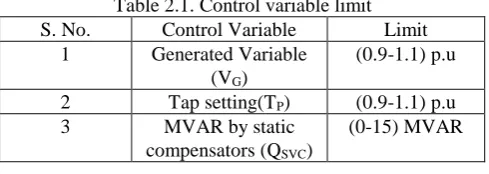
Control variable limit
The control variable limits for the Generator bus voltages, Transformer Tap Settings and VAR compensators are given below:
Table 2.1. Control variable limit S. No. Control Variable Limit
1 Generated Variable (VG)
(0.9-1.1) p.u
2 Tap setting(TP) (0.9-1.1) p.u
3 MVAR by static
compensators (QSVC)
(0-15) MVAR
Two different objective functions are considered to optimize the reactive power in the system.
The system is incorporated with the various parameters like real power, frequency, speed, etc., can be considered for the problem formulation but the voltages and reactive power as the main parameter because in distribution, the reactive power cannot be supplied fully and hence they can be rectified by using compensators.
The parameters of the voltage will be checked within the variable limit and also the tap setting of the position of transformer is also checked. This makes the system to remain in stability and also minimizes the voltage deviations in the power system.
3. KRILL HERD ALGORITHM
3.1 Herding Behaviour of Krill Swarms
This paper describes one such observation made on the Antarctic Krill species. This is considered as one of the best studied marine animal species. These krill are capable of forming large groups of swarms with no parallel orientation existing between them. Since decades, studies are carried out to understand the herding mechanism of the krill and the individual distribution of the krill among the herds. The studies made clear some of the factors in spite of some uncertainties observed. It says, the basic unit of the organization is the ‘krill swarm’. As mentioned earlier, one important factor considered here is the presence of the predator. When one krill is affected by the predator, that krill is abandoned from the herd, which in turn reduces the density of the swarm. The increase in the krill density and distance from the food is always the phenomenon or the criteria to be reached during the formation of the herds. Hence, it can be called as one multi-objective mechanism.
The optimum solution or the global minima is attained considering the two main objectives of density-dependent attraction of the krill and areas of high food concentration. The relation between the objective function and the krill position is proportionate in nature. The global minimum, or less objective function value, implies the minimum distance of a krill from the highest density and food in the solution. The objective function of the algorithm is determined with some coefficients determined after a brief empirical study. The krill individuals always try to move towards the best solution in this process.
3.2. Lagrangian Model of Krill Herding
The Lagrangian model states the objective function of the Krill Herd algorithm. The fitness function of a krill is a combination of the highest density of the krill and the distance of food from the krill. The fitness value gives the imaginary distances of the krill from the herd density and food. In a two dimensional surface, the time-dependent position of a krill is mainly influenced/controlled by the following three factors:
(i) Movement induced by other krill individuals (ii) Foraging activity
(iii)Random diffusion
3.2.1. Motion Induced by other Krill Individuals
The fitness function of the algorithm mainly depends on the density of the krill in the search space. So, it is essential to maintain a high krill density in order to achieve an optimum solution. The individuals keep on rebuilding the system maintaining this high density under the influence of the other individuals. The movement of a krill individual is mainly dependent on the neighbouring krill individuals and the mutual effects between them.
© 2017 AJAST All rights reserved. www.ajast.net = + + (1)
Where,
- Motion induced on krill individual due to the other krill individuals
- Foraging motion - Random diffusion
3.3. Features of Krill Herd Optimization Algorithm
Best optimized value.
Design of algorithm is very easy.
Concept is very easy to understand and Chaotic krill herd algorithm is faster and convergence profile
3.4. Algorithm Steps to be followed.
a)Search space identification. b)Randomized initialization. c)Fitness evaluation of agents.
d)Update S(t), best(t), worst(t)and Mi(t) for i = 1,2,. . .,N. e)Calculation of the total force in different directions. f)Calculation of motion of the particles and velocity. g)Updating agents’ position.
h)Repeat steps c to g until the stop criteria is reached.
STEP1
Initialization: initialize the parameter like generation counter, population fitness function evaluation, maximum induced speed, foraging speed and diffusion speed.
STEP 2
Fitness evaluation: Generated randomly the position set of each krill individual and evaluated the fitness function value for each krill individuals.
STEP3
While, for i=1: np do
Calculation the following motion (a)Induced motion
(b)Foraging motion (c)Physical motion Apply the genetic operator End for
M=m+1;
STEP 4
Post position of the results
4. PROBLEM FORMULATION
4.1 Problem Description
The objective function of this work is to find the optimal settings of reactive power control variables including the rating shunt of var compensating devices which minimizes the real power loss.
4.1.1. Minimization of P Loss
The general formulation of P loss minimization problem may be expressed as follows.
minimize J1(x1, x2) = minimize P Loss
2 2
1
2
cos
...(1)
LN
loss K i j i j i j
K
P
G
V V
V V
Where J1(x1, x2) is the active power transmission loss.
4.1.2. Minimization of TVD
The general formulation of TVD minimization objective may be stated as
Minimize J2(x1, x2) = minimize TVD
TVD = |……… (2)
Where J2(x1, x2) is the TVD minimization objective function, Vp is the voltage at bus p and V ref is the desired value of the voltage magnitude of the p th bus, taken as 1 pu.
4.1.3. Improvement of VSI
The general objective of VSI improvement problem may be stated as in (6) where Lk is the voltage stability indicator (L-index) of the kth node. The value of Lk may be written as.
1
( , )
...(2)
ND
sp
i i
i
VD x u
v
v
4.2. Constraints
4.2.1 Equality constraints
In (2), g is the set of equality constraints representing the load flow equations given by
1 cos( )...(3)
NB
gi Di j i j ij ij j i P P
V V Y
Y Y1
sin(
)...(4)
NB
gi Di j i j ij ij i j
Q
Q
VV Y
Y
Y
4.2.2. Inequality constraints
In set of system inequality constraints presented below:
4.2.2.1Generator constraints: For all the generator voltages (including slack bus), real and reactive power outputs (including slack bus) must be restricted within their lower and upper limits as stated in.
min max
gi gi gi
V
V
V
i=1, 2…….NG ……… (5)
min max
gi gi gi
Q
Q
Q
i=1, 2……..NG………….. (6)
4.2.2.2 Transformer constraints: Transformer tap settings must be within their specified lower and upper limits as,
max
1 1
L L
S
S
i=1, 2…….NTL………. (7)
4.2.2.3 Shunt VAR compensator constraints: Reactive
© 2017 AJAST All rights reserved. www.ajast.net max
1 1
L L
S
S
i=1, 2…….NTL………. (8)
4.2.2.4 Security constraints: These include the constraints on voltages at load buses and transmission line loadings. Each of these Constraints must be within their lower and upper operating limits, as expressed in (13) and (14), respectively
max max
i i i
T
T
T
i=1, 2……NT…. (9)
5.RESULTS & DISCUSSIONS
5.1 Numerical values
The objective of minimization of power loss is considered in this case. The optimal settings of control variables that minimize the power loss is minimum are obtained as shown in below table
Table 5.1. Optimal numerical values S.
No.
Control
variables Initial ABC KHA CKHA
1 1.05 1.1 0.9985 1.0356
2 1.04 1.0615 1.0014 1.0489
3 1.01 1.0711 0.9914 1.0258
4 1.01 1.0849 1.0019 1.0411
5 1.05 1.1 1.0145 1.02
6 1.05 0.0665 1.0207 0.9532
7 1.078 0.97 1.0187 0.9634
8 1.069 1.05 1.0149 0.9856
9 1.032 0.99 0.0341 0.9474
10 1.068 0.99 0.0139 0.0078
11 0 5 0.0081 0.002
12 0 5 0.0394 0.0136
13 0 5 0.0000 0.0398
14 0 5 0.0241 0.0285
15 0 4.1 0.0000 0.0618
16 0 3.3 0.02145 0.0143
17 0 0.9 0.0000 0.0781
18 0 5 8.1000 0.0473
19 0 2.4 0.0425 0.0156
5.2 Minimization of Objective Function
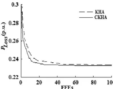
Minimizing the power loss shown by the new algorithm is better power loss very much that improves the profile of voltage stability, TVD, minimization of power loss in load buses.
Table 5.2. Minimization of objective function
S.No. Parameter Initial value CKHA
1 29.05 3.2189
2 TVD 20.44 1.3254
3 L-index 8.42 0.1436
5.3 Comparison of Basic KHA AND CKHA
Fig. 5.1 A plot (pu) for ploss minimization objective
Fig. 5.2 Plot (pu) for TVD minimization objective
Fig. 5.3 L-index (pu) for VSI improvement objective
6. CONCLUSION
© 2017 AJAST All rights reserved. www.ajast.net
REFERENCES
[1] Carpentier, J.: “Optimal power flows”, Int. J. Electr. Power Energy Syst., 1979, 1(1), pp. 3–15.
[2] Dommel, H.W., Tinney,W.F.: “Optimal power flow solutions”, IEEE Trans. Power Appar. Syst., 1968, PAS-87(10), pp. 1866–1876.
[3] Sachdeva, S.S., Billinton, R.: “Optimum network VAR planning by nonlinear programming”, IEEE Trans. Power Appar. Syst., 1973, PAS-92(4), pp. 1217–1225.
[4] Mota-Palomino, R., Quintana, V.H.: “Sparse reactive power scheduling by a penalty-function linear programming technique”, IEEE Trans. Power Syst., 1986, 1(3), pp. 31–39.
[5] Aoki, K., Fan, M., Nishikori, A.: “Optimal VAR planning by approximation method for recursive mixed-integer linear programming”, IEEE Trans. Power Syst., 1988, 3(4), pp. 1741–1747.
[6] Quintana, V.H., Santos-Nieto, M.: “Reactive-power dispatch by successive quadratic programming”, IEEE Trans. Energy Convers., 1989, 4(3), pp. 425–435.
[7] Deeb, N., Shahidehpour, S.M.: “Linear reactive power optimization in a large power network using the decomposition approach”, IEEE Trans. Power Syst., 1990, 5(2), pp. 428–438.
[8] Bjelogrlic, M., Calovic, M.S., Ristanovic, P., et al.: “Application of Newton’s optimal power flow in voltage/reactive power control”, IEEE Trans. Power Syst., 1990, 5(4), pp. 1447–14.
[9] Lu, F.-C., Hsu, Y.-Y.: “Reactive power/voltage control in a distribution substation using dynamic programming”’, IEEE Proc. Gener. Transm. Distrib., 1995, 142(6), pp. 639–64.
[10] Yan, W., Yu, J., Yu, D.C., et al.: “A new optimal reactive power flow model in rectangular form and its solution by predictor corrector primal dual interior point method”, IEEE Trans. Power Syst., 2006, 21(1), pp. 61–67.
[11] Yoshida, H., Kawata, K., Fukuyama, Y., et al.: “A particle swarm optimization for reactive power and voltage control considering voltage security assessment”, IEEE Trans. Power Syst., 2000, 15(4), pp. 1232–1239.
[12] Esmin, A.A.A., Lambert-Torres, G., de Souza, A.C.Z.: “A hybrid particle swarm optimization applied to loss power minimization”, IEEE Trans. Power Syst., 2005, 20(2), pp. 859–866.