Volume 5, Issue 8 (January 2013), PP. 62-74
Two-Layer Fuzzy Logic Based Load-Frequency
Controller for a Two-Area Interconnected Power System
Considering Nonlinearities with Super Capacitor Energy
Storage Units
V. Adhimoorthy
1, Dr.I.A. Chidambaram
21Assistant Professor, Department of Electrical Engineering, Annamalai University, Annamalainagar- India 2Professor Department of Electrical Engineering, Annamalai University, Annamalainagar - India
Abstract:- This paper proposes a sophisticated application of Super Capacitor Energy Storage (SCES) unit for the improvement of the Load-Frequency Control in a two-area interconnected power system considering Governor Dead Band (GDB) and Generation Rate Constraints (GRC) nonlinearities. In this paper, the proposed fuzzy controller, called as two layered fuzzy controller, consists of two layers. The first layer is called compensator, which is used to generate and update the reference value of Area Control Error (ACE). The second layer called feedback fuzzy logic controller, makes ACE decay to zero at steady state. The proposed two layered fuzzy controller, with the updated reference value of Area Control Error using pre-compensator ensures the ACE to zero with the inclusion of Proportional plus Integral (PI) controllers. The Integral Square Error (ISE) criterion is adopted in optimizing the PI controller gains. In addition to levelling load, the SCES is advantageous for secondary control in the power system and maintains the power quality. When an AC power system is subjected to load disturbances, considerable frequency oscillations may result to system instability. So as to ensure the system stability, the power modulation control offered by SCES is enhanced to suppress the peak value of the transient frequency deviation. Simulation results show that the proposed two layered fuzzy logic controller is not only effective in damping out the frequency oscillations, but also capable of alleviating the transient frequency swing caused by large load disturbance. Moreover, the output results obtained proves that the proposed two layered fuzzy load frequency controller provides very good transient and steady state response compared to the fuzzy controller and conventional PI controllers.
Keywords:- Load-Frequency Control, Area Control Error, Integral Squared Error criterion, Fuzzy logic controller, Two Layer Fuzzy Logic Controller, Super Capacitor Energy Storage Unit, Governor Dead Band, Generation Rate Constraints.
INTRODUCTION
Load Frequency Control (LFC) is a very important issue in power system due to the increasing load demand and results to more complicated environment which requires adequate and efficient control. Therefore the objective of LFC of a power system is to maintain the frequency of each area and tie-line power flow (among the interconnected system) within specified tolerance by adjusting the new outputs of LFC generators so as to accommodate the fluctuating load demand. A number of control schemes have been employed for the design of load frequency controllers [1] in order to achieve better dynamic performance. Among the various types of load frequency controllers the most widely conventional types used are the tie-line biased control and flat frequency control to achieve the above goals of LFC, both schemes are based on the classic controls which work on the same function made up of the frequency and tie-line power deviations. Nevertheless these conventional control systems have been successful to some extent only [2]. This suggests the necessity of more advanced control strategies to be incorporated for better control. In this aspect a better power quality intelligent controllers [2-8] be adopted replacing the conventional controllers because of their ability in ensuring fast and good dynamic response for the load frequency control problems.
dynamic performance of load-frequency control system. Moreover, the GDB has a destabilizing effect on the transient response of the system [9]. In a power system, another most important constraint on modern large size thermal units is the stringent generation rate constraint i.e. the power generation can change only at a specified maximum rate. The GRC of the system is considered as a limiter to the control system [10]. In this condition, the response will be with larger overshoots and longer settling times when compared with the system where GRC is not considered. So, if the parameters of the controller are not chosen properly, the system may become unstable. In the simultaneous presence of GDB and GRC, even with small load perturbation, the system becomes highly nonlinear and hence the optimization problem becomes rather complex [11]. Even though many control strategies have been efficiency in the design of load-frequency controller for interconnected power systems considering GDB and GRC nonlinearities [9-11] because of the future vast competitive environment, the stabilization of frequency oscillations in the interconnected power system becomes challenging. So advanced economic, high efficiency and improved control schemes are required to ensure the power system reliability.
The conventional load-frequency controller may no longer be able to attenuate the large frequency oscillation due to the slow response of the governor. A fast-acting energy storage system in addition to the kinetic energy of the generator rotors provides adequate control to damp out the frequency oscillations. The problems like low discharge rate, increased time required for power flow reversal and less maintenance requirements have led to the evolution of Super Capacitor Energy Storage (SCES) or Ultra Capacitor Energy Storage (UCES) devices for their utilization as load frequency stabilizers. Super Capacitors are electrochemical type capacitor which offer large capacitances in the order of thousands of farads at a low voltage rating of about 2.5V [12, 13]and are used to store electrical energy during surplus generation and deliver high power within a short duration of time especially during the peak-load demand period [14, 15].The energy density of Super Capacitor(SC) is 100 times larger than the conventional electrolytic capacitor and their power density is 10 times larger than the lead-acid battery. Ultra capacitors possess a number of attractive properties like fast charge-discharge capability, longer life, no-maintenance and environmental friendliness. The effective specific energy for a prescribed load can be satisfied using various SC bank configurations. The SCES will, in addition to load levelling, a function conventionally assigned to them, have a wide range of applications such as power quality maintenance for decentralized power supplies. The SCES are excellent for short-time overload output and the response characteristics possessed in the particular. The effect of generation control and the absorption of power fluctuation required for power quality maintenance are expected. However, it will be difficult to locate the placement of SCES alone in every possible area in the interconnected system due to the economical reasons. In this paper SCES unit is located in area 1 of the two-area interconnected reheat thermal power system considering GDB and GRC nonlinearities.
Fuzzy logic controllers have received considerable interest in recent years. Fuzzy based methods are found to be very useful in the places where the solution to the mathematical formulations is complicated. Moreover, fuzzy logic controller often yields superior results to conventional control approaches [2-5]. The fuzzy logic based intelligent controllers are designed to facilitate the operation smooth and less oscillatory when system is subjected to load disturbances. In this paper, the control scheme consists of two layers viz fuzzy pre-compensator and fuzzy PI controller. The purpose of the fuzzy pre-pre-compensator is to modify the command signals to compensate for the overshoots and improve the steady state error. Fuzzy rules from the overall fuzzy rule vectors are used at the first layer, linear combination of independent fuzzy rules are used at the second layer. The two layer fuzzy system has less number of fuzzy rules as compared with the fuzzy logic system. The proposed two layered fuzzy logic controllers give better simulation results which is compared with the simulation results obtained using the fuzzy logic controllers and conventional controllers. Thus the two layer fuzzy PI controller enhances an efficient way of coping even with imperfect information, offers flexibility in decision making processes
II. PROBLEM FORMULATION
The state variable equation of the minimum realization model of „
N
‟ area interconnected power system [23] may be expressed as
Cx y
d u x x
(1)
Where e(N-1) TN T T
1) -(N ei T
1 , p ...x , p ...x ] [x
x ,
n
- state vector
n
N
i
i N n
1
u[u1,...uN]T [PC1...PCN]T,N - Control input vector d d d PD PDN T N
T
N] [ ... ] ,
,...
[ 1 1
- Disturbance input vector y[y1...yN]T , 2N- Measurable output vector
Where A is system matrix, B is the input distribution matrix, is the disturbance distribution matrix,
C is the control output distribution matrix,
x
is the state vector,u
is the control vector andd
is the disturbance vector consisting of load changes. In order to ensure zero steady state error condition an integral controller may suitability designed for the augmented system along with the optimized proportional controller. To incorporate the integral function in the controller, the system Eq (1) is augmented with new state variables defined as the integral ofACEi
vidt,i1,2,...N. The augmented system of the order (N+n) may be describedd u x A x
(2)
Where n
N vdt
} } x
x
B B A C
A 0
0 0
and
0
The problem now is to design the decentralized feedback control law
ui kiT yi i1,2...N (3)
The control law in Eq (3) may be written in-terms of
v
i asN i
v k dt v k
ui i1
i i2 i , 1,2.... (4)Where
i1, i2
Ti k k
k is a two dimensional Integral and proportional feedback gain vector,
v
i is the scalar control output of area iIII. APPLICATION OF THE MATHEMATICAL MODEL OF SUPER CAPACITOR ENERGY STORAGE UNIT FOR A TWO- AREA THERMAL REHEAT INTERCONNECTED POWER SYSTEM CONSIDERING GDB AND GRC NONLINEARITIES 3. 1 Super Capacitor Energy Storage Units
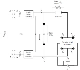
Fig 1 Super Capacitive Energy Storage Unit
A Super Capacitive Energy Storage (SCES) consists of, from circuit point of view, a super capacitor or a Cryogenic Hyper Capacitor (CHC), a Power Conversion System (PCS) and the associated protective circuitry as shown in Fig.1.The CHCs differ from the conventional capacitors in that they are multilayer ceramic capacitors with a dielectric that has its peak dielectric constant at 77 K, the temperature of liquid nitrogen. The dimensions of the capacitor are determined by the energy storage capacity required. The storage capacitor C may consists of many discrete capacitance units connected in parallel. The resistor R1 connected in parallel
the event of a converter failure. The dc breaker allows current Id to be diverted into the energy dump resistor RD
if the converter fails. Assuming the losses to be negligible, the bridge voltage Ed is given by
Ed = 2Ed0cosα – 2IdRD (5)
By changing the relative phase angle α of this pulse through a range from 0 to 180 voltage across the capacitor, Ed can be made to vary from its maximum positive value to the maximum negative value. The
voltage pulses from the firing circuits are timed to cause each SCR to begin conduction at a prescribed time. The sequence maintains a constant average voltage across the capacitor. The exact timing of the firing pulses relative to the phase of 50 Hz AC voltage determines the average dc voltage across the capacitor. Since the bridges always maintain unidirectional current and Ed is uniquely defined by α for positive and negative values, the
power flow Pd in the capacitor is uniquely determined by α in both magnitude and direction. Thus, without any
switching operation, reversibility as well as magnitude control of the power flow is achieved by continuously controlling the firing angle α. The firing angle of the converter is controlled by an algorithm determined by utility needs, but basically the control circuit responds to a demand signal for a certain power level, either positive or negative. Then based on the voltage across the capacitor, a firing angle is calculated and transmitted to the firing circuit. The response time of the control and firing circuits to a new demand signal are so short that a new firing angle may be chosen for the very next SCR to be pulsed, say within a few milliseconds. This rapid response to power demands that may vary by hundreds of megawatts is a unique capability of SCES relative to other energy storage systems such as pumped hydro, compressed air, flywheels etc. This ability to respond quickly allows the SCES unit to function not only as an energy storage unit but also as a spinning reserve and to provide stability in case of disturbances on the utility system. The reversing switch arrangement provided accommodates the change of direction of the current in the capacitor during charging (rated load period) and discharging (during peak load period), since the direction of the current through the bridge converter (rectifier/inverter) cannot change. During the charging mode, switches S1 and S4 are on and S2 and S3 are off. In
the discharging mode, S2 and S3 are on and S1 and S4 are off.
3.2 Block diagram representation of SCES unit
Fig.2 block diagram with capacitor voltage deviation feedback
The normal operating point of the capacitor can be such that the maximum allowable energy absorption equals the maximum allowable energy discharge. This will make the SCES unit very effective in damping the oscillations created by sudden increase or decrease in load. If Ed0 denotes the set value of voltage and Edmax and
Edmin denote the maximum and minimum limits of voltage respectively, then,
(6)
= (7) The capacitor voltage should not be allowed to deviate beyond certain lower and upper limits. During a
sudden system disturbance, if the capacitor voltage goes too low and if another disturbance occurs before the voltage returns to its normal value, more energy will be withdrawn from the capacitor which may cause discontinuous control. To overcome this problem, a lower limit is imposed for the capacitor voltage and in the present study; it is taken as 30% of the rated value. Initially, the capacitor is charged to its set value of voltage Ed0 (less than the full charge value) from the utility grid during its normal operation. To charge the capacitor at
the maximum rate, Ed is set at its maximum value by setting α = 0°. At any time during the charging period, the
stored energy in Joules is proportional to the square of the voltage as described.
Once the voltage reaches its rated value, it is kept floating at this value by a continuous supply from PCS which is sufficient to overcome the resistive drop. Since this Ed0 is very small, the firing angle α will be
mechanisms start working to set the power system to an equilibrium condition, the capacitor charges to its initial value of voltage Ed0. The action during sudden releases of load is similar that the capacitor immediately gets
charged instantaneously towards its full value, thus absorbing some portion of the excess energy in the system, and as the system returns to its steady state, the excess energy absorbed is released and the capacitor voltage attains its normal value. The power flow into the capacitor at any instant is
Pd = Ed Id (8)
And, the initial power flow into the capacitor is
Pd0 = Ed0.Id0 (9)
Where Ed0 and Id0 are the magnitudes of voltage and current prior to the load disturbance. When a load
disturbance occurs, the power flow into the coil is
Pd0 + ΔPd = (Ed0 + ΔEd)(Id0 + ΔId) (10)
so that the incremental power change in the capacitor is
ΔPd = (Id0ΔEd + ΔEd ΔId) (11)
The term Ed0.Id0 is neglected since Ed0 = 0 in the storage mode to hold the rated voltage at constant value.
3.3 Mathematical Model of SCES unit
Either frequency deviation or Area Control Error (ACE) can be used as the control signal to the CES unit (Δerrori = Δfi or ACEi). Edi is then continuously controlled in accordance with this control signal. For the ith
area, if the frequency deviation Δfi (i.e., Δerrori = Δfi). of the power system is used as the control signal to CES,
then the deviation in the current, ΔIdi is given by
ΔIdi = [ ][KsCESi.Δfi - Kvdi. Δ ] (12)
If the tie-line power flow deviations can be sensed, then the Area Control Error (ACE) can be fed to the CES as the control signal (i.e., Δerrori = ACEi). Being a function of tie-line power deviations, ACE as the
control signal to CES, may further improve the tie-power oscillations. Thus, ACE of the two areas are given by
ACEi = BiΔfi + ΔPtie ij ; i, j = 1, 2 (13)
Where ΔPtie ij is the change in tie-line power flow from area i to j. Thus, if ACEi is the control signal
to the SCES, then the deviation in the current ΔIdi would be
ΔIdi = [ ][ KsCESi.ΔACEi -Kvdi.Δ ]; i,j=1,2 (14)
IV.SYSTEM MODELING FOR CONTROL SYSTEM
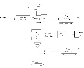
The control actions of Super Capacitor Energy Storage units are found to be superior to the action than that of the governor system in terms of the response speed against, the frequency fluctuations [15]. The SCES units are tuned to suppress the peak value of frequency deviations quickly against the sudden load change, subsequently the governor system are actuated for compensating the steady state error of the frequency deviations. Fig 3 shows the linearized reduction model for the control design of two area interconnected power system with SCES units. The SCES unit is modelled as an active power source to area 1 with a time constant TSCES, and gain constant KSCES. Assuming the time constants TSCES is regarded as 0 sec for the control design
[15]. Then the state equation of the system represented by Fig 3 becomes.
Fig. 3 Linearized reduction model for the control design
4.1 Control design of Super Capacitor Energy Storage unit
The design process starts from the reduction of two area system into one area which represents the Inertia centre mode of the overall system. The controller of SCES is designed for the equivalent one area system to reduce the frequency deviation of inertia centre. The equivalent system is derived by assuming the synchronizing coefficient T12 to be large. From the state equation of
P
T12 in Eq (15)2 1
12 12
2 T F F
PT
(16)
Setting the value of T12 in Eq (16) to be infinity yields ΔF1 = ΔF2. Next, by multiplying state equation of
2 1
and
F
F
in Eq (15) by1 1 p p
k
T
and 2 12 2 p pk
a
T
respectively, then SCES T p p p P P F k F k T 1 12
1 1
1
1 1
(17) 12 2 12 2 2 2 12 2 1 T p p p P F a k F k a T (18) By summing Eq (17) and Eq (18) and using the above relation ΔF1 = ΔF2 = ΔF
D SCES p p p p p p p p p p P C P a k T k T F a k T k T a k k
F
12 2 2 1 1 12 2 2 1 1 12 2 1 1 1 1 (19)
Where the load change in this system ΔPD is additionally considered, here the control ΔPSCES = -KSCES ΔF is
applied then. D SCES P B K A s C F (20) Where 12 2 2 1 1 12 2 1 1 1 a k T k T a k k A p p p p p p 12 2 2 1 1 1 a K T K T B p p p p
percent reduction of the final value after applying a step change ΔPD can be given as a control specification. In
Eq (20) the final values with KSCES = 0 and with KSCES0 are C/A and C/(A+KSCES B) respectively therefore the
percentage reduction is represented by
100 )
/
(C A R
B) K
+
C/(A SCES
(21) For a given R, the control gain of RFB is calculated as
(100 R)
BR A
KSCES (22)
V. DESIGN OF FUZZY LOGIC SYSTEM
Fuzzy logic systems belong to the category of computational intelligence technique. One advantage of the fuzzy logic over the other forms of knowledge-based controllers lies in the interpolative nature of the fuzzy control rules. The overlapping fuzzy antecedents to the control rules provide transitions between the control actions of different rules. Because of this interpolative quality, fuzzy controllers usually require far fewer rules than other knowledge-based controllers [16].
Fig. 4 Block diagram of fuzzy logic controller
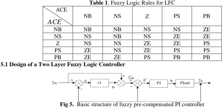
A fuzzy system knowledge base consists of a fuzzy if then rules and membership functions characterizing the fuzzy sets. The block diagram and architecture of fuzzy logic controller is shown in fig 4. Membership Function (MF) specifies the degree to which a given input belongs to a set. Here triangular membership function have been used to explore best dynamic responses namely Negative Big (NB), Negative Small (NS), zero (ZE), Positive Small (PS), Positive Big(PB). Fuzzy rules are conditional statement that specifies the relationship among fuzzy variables. These rules help to describe the control action in quantitative terms and have been obtained by examining the output response to the corresponding inputs to the fuzzy controllers. Defuzzification, to obtain crisp value of FLC output is done by centre of area method. The fuzzy rules are designed as shown in Table 1.
Table 1. Fuzzy Logic Rules for LFC ACE
.
ACE
NB NS Z PS PB
NB NB NB NS NS ZE NS NS NB NS ZE ZE Z NS NS ZE ZE PS PS ZE NS ZE PS PS PB ZE ZE PS PB PB
5.1 Design of a Two Layer Fuzzy Logic Controller
Fig 5. Basic structure of fuzzy pre-compensated PI controller
k
n i pe k TK e n
k k u
0
) ( )
( )
( (23)
Where e(k)y(k)yr(k) and ∆ e(K) = e (k) - e(k-1)
The controller output, process output and the set point are denoted as u, y and
y
r respectively. Experience-based tuning method - Ziegler-Nichols method which widely adopted [17] requires a close attention since the process has to be operated near instability to measure the ultimate gain and period. This tuning technique may fail to tune the process with relatively large dead time [17]. In order to improve the performance of PI tuning a number of attempts have been made which can be categorized into two groups: Set point modification and gain modification. The set point modification introduces new error terms
e
p
y
r(
k
)
F
p(
e
,
e
)
y
(
k
)
(24)
e
i
y
r(
k
)
F
i(
e
,
e
)
y
(
k
)
(25)The corresponding control law is given by, Where
F
p,F
i are non linear functions of e and ∆e.
k
n i i p
pe k TK e n
k k u
0
) ( )
( )
(
(26) As a special case, the set point is being modified only in proportional terms which implies
F
p= β;F
i=1 setpoint weight [18]
k
n i r
p y k y k TK e n
K k U
0 ) ( )}
( ) (
{ (27)
k
n i pe k TK e n K
k U
0
) ( ' '
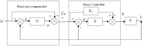
The pre-compensation scheme [18, 19] is easy to implement in practice, since the existing PI control can be used without modification in conjunction with the fuzzy pre-compensator as shown in Fig 6. The procedure of rule generation consists of two parts (i) learning of initial rules which determines the linguistic values of the consequent variables. (ii) fine tuning adjusts the membership function of the rules obtained by the previous step. The structure of the pre-compensation rule is written as If e is Le, and e is Le then C is Lc
where Le, Le and Lc are linguistic values of e, e, c respectively. Each fuzzy variable is assumed to take 5
linguistic values Le, Le, or Lc = {NB, NS, ZE, PS, and PB} this leads to fuzzy rules, if the rule base is
complete
Fig 6. Proposed two layered fuzzy logic controller The dynamics of overall system is then described by following equations
e(k)ym(k)yp(k) (28) e(k)e(k)e(k1) (29)
(k)G[e(k),e(k)] (30) Where (k) is a compensating term which is generated using a fuzzy logic schemey'm(k)ym(k)(k) (31)
e'(k) y'm(k)yp(k) (32)
used to update and modify the reference value of the output signals to damp out the oscillations. The fuzzy states of the input and output all are chosen to be equal in number and use the same linguistic descriptors as N = Negative, Z = Zero, P = Positive to design the new fuzzy rules. The fuzzy logic rules for pre- compensator are presented in Table-2.
Table 2. Fuzzy Logic Rules for Pre compensator ACE
E C
A N Z P
N N N Z
Z Z Z p
P Z P P
The second layer which is known as feedback fuzzy logic control reduces the steady state error to zero. The output of the FLC is given by
u(k)K1y,m(k)F[e,(k),e,(k)] (34)
5.2 Application of Two Layered Fuzzy Logic controller for the two- area interconnected Power System considering GDB and GRC nonlinearities withSCES units
The Linearized model of two- area reheat thermal interconnected power system with
SCES unit is shown in Fig 7.
Fig.7. Linearized model of Two Layered Fuzzy Logic Controller two- area interconnected reheat thermal power system considering GDB and GRC nonlinearities with SCES units
The objective of LFC is to re-establish primary frequency regulation, restore the frequency to its nominal value as quickly as possible and to minimize the tie-line power flow oscillations between neighbouring control areas. In order to satisfy the above requirement, the gain values of the Proportional (Kp1, Kp2) and
integral (Ki1, Ki2) integral controllers in LFC loop are to be optimized to have minimum undershoot (US),
overshoot (OS) and settling time (ts) in area frequency deviations and power exchange deviations over tie-line. In the present work, an Integral Square Error (ISE) criterion is used to minimize the objective function defined as follows [21]
(35)
VI. SIMULATION RESULTS AND OBSERVATIONS
The optimal gains of the conventional PI controller are determined on the basis of Integral Squared Error (ISE) technique by minimizing the quadratic performance index. These controllers are implemented in a two- area interconnected reheat thermal power system considering GDB and GRC nonlinearities for 1% step load disturbance in area 1 without and with SCES unit. The nominal parameters are given in Appendix. The gain values of SCES (KSCES) are calculated using Eq (22) for the given value of speed regulation coefficient (R).
The gain value is of the super capacitor is found to be KSCES = 0.67. The conventional optimum gain values of
the PI controllers are found to be KP1 = KP2 = 0.3 and KI1 = KI2 = 0.25 using MATLAB 7.01 software. Moreover
the fuzzy logic and two layered fuzzy logic controller are designed and implemented in the interconnected two area power system without and with SCES unit for 1% step load disturbance in area 1. The fuzzy rules are designed according to ACE is shown in Table 1 and 2. The comparative transient response from Fig 8 and 9, it can be observed that the oscillations in area frequencies, tie-line power deviation and control input requirements have decreased to a considerable extent for the system with the use of two layered fuzzy logic controller as compared to that of the system with using PI controller or fuzzy controller.
Moreover the Super Capacitor Energy Storage unit is located in area 1 which is made to ensure the coordinated control action along with the governor unit to enable more improvement in the inertia mode oscillations as shown in Fig11. It is also evident that the settling time and peak over/under shoot of the frequency deviations in each area and tie-line power deviations decreases considerable amount with use of
F
F
P
dt
J
t
tie
0
2 12 2
2 2 2 1
1
SCES unit. In Fig 12, it should be noted that SCES coordinated with governor unit requires lesser control effort. Fig 10 and Fig 13 shows the generation responses for the four case studies as the load disturbances have occurred in area 1, at steady state, the power generated by the generating units in both areas are in proportion to the area participation factors. From the Table-3 it can be observed that the controller design using Two layered fuzzy logic controller for two area thermal reheat power system with SCES unit have not only reduces the cost function but also ensure better stability, as they possesses less over/under shoot and faster settling time. Thus SCES unit coordinated with governor unit improves not only inertia mode but also the inter area mode oscillations effectively.
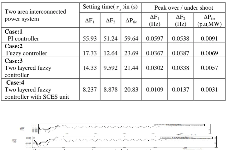
Table 3. Comparison of the system performance for the four case studies
Fig.8.Dynamic responses of the frequency deviations and tie-line power deviation of a two-area thermal reheat interconnected Power System with GDB and GRC nonlinearities Considering a step
load disturbance of 0.01p.u.MW in area 1
Fig. 9. Dynamic responses of the Control input deviations of a two-area thermal reheat interconnected Power System with GDB and GRC nonlinearities considering a step load disturbance of 0.01p.u.MW in area 1
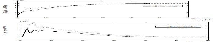
Fig 10. Dynamic responses of the required additional mechanical power generation for two-area thermal reheat interconnected Power System with GDB and GRC nonlinearities considering a step load disturbance of 0.0
p.u.MW in area 1 Two area interconnected
power system
Setting time(s)in (s) Peak over / under shoot
F1 F2 Ptie
F1
(Hz)
F2
(Hz)
Ptie
(p.u.MW) Case:1
PI controller 55.93 51.24 59.64 0.0597 0.0538 0.0091
Case:2
Fuzzy controller 17.33 12.64 23.69 0.0367 0.0387 0.0069
Case:3
Two layered fuzzy controller
14.33 9.592 21.44 0.0302 0.0338 0.0057
Case:4
Two layered fuzzy controller with SCES unit
Fig.11. Dynamic responses of the frequency deviations and tie line power deviation of a two area thermal reheat interconnected Power System considering GDB and GRC nonlinearities without / with SCES units
considering a step load disturbance of 0.01p.u.MW in area 1 using two layered fuzzy logic controller
Fig. 12. Dynamic responses of the Control input deviations of a two-area thermal reheat interconnected Power System considering GDB and GRC nonlinearities without /with SCES units considering a step load disturbance of 0.01p.u.MW in area 1 using two layered fuzzy logic controller
Fig.13. Dynamic responses of the required additional mechanical power generation of a two-area thermal reheat interconnected Power System considering GDB and GRC nonlinearities without / with SCES units
considering a step load disturbance of 0.01 p.u.MW in area 1 using two layered fuzzy logic controller
VII. CONCLUSION
A Two Layered Fuzzy logic based PI controllers were designed and implemented for a two-area thermal reheat interconnected power system with GDB and GRC nonlinearities with super capacitor energy storage device. In this, the control scheme consists of two layers viz fuzzy pre-compensator and fuzzy PI controller. Fuzzy rules from the overall fuzzy rule vectors are used at the first layer, linear combination of independent fuzzy rules are used at the second layer. The two layer fuzzy system has less number of fuzzy rules as compared with the fuzzy logic system. Simulation result ensures that the two layered fuzzy logic controllers give better simulation results when compared with the simulation results obtained using the fuzzy logic controllers and conventional controllers for the system without super capacitor energy storage unit.
Acknowledgement:
The authors wish to thank the authorities of Annamalai University, Annamalainagar, Tamilnadu, India for the facilities provided to prepare this paper.
REFERENCES
[1] Shayeghi.H, Shayanfar.H.A, Jalili.A, “Load-frequency control strategies: A state of the art survey for the researcher” Energy Conversion and Management, Vol. 50(2), pp.344-353, 2009.C.C. Lee, “Fuzzy Logic in control systems Fuzzy logic controller, Part-1”, IEEE Transactions on System, Man and Cybernetics, Vol. 20(2), pp.419-435, 1990.
[2] C.S. Indulkar and Baldevraj, “Application of fuzzy Controller to automatic generation Control”, Electric Machines and Power Systems, Vol. 23, pp.209-220, 1995.
[3] Zadeh. L.A., “Fuzzy Algorithm–Information and Control”, Vol. 12, pp.94 – 102, 1969
[4] M.K.EL-Sherbiny, G.EL-Saady, Ali M. Yousef, “Efficient fuzzy logic load frequency controller”, Energy Conversion and Management Vol.43, pp.1853-1863, 2002.
[5] H.D.Mathur, H.V.Manjunath, “Study of dynamic performance of thermal units with asynchronous tie-lines using fuzzy based controller”, Journal of Electrical Systems, Vol. 3, pp.124- 130, 2007.
[6] J.K.Kim, J.H.Park, Swale, K.P.Chong, “A Two-Layered Fuzzy Logic Controller for Systems with Dead zones”. IEEE Transactions on Industrial Electronics, Vol-41, No. 2, pp.155-166, 1994.
[7] Ahmed Rubaai, Abdul R.Ofoli, “Multilayer fuzzy controller for power networks”, IEEE Transaction on Industrial Applications, Vol. 40, No.6, pp.1521-1528, 2004.
[8] S.C.Tripathy, G.S.Hope, O.P.Malik, “Optimization of load frequency control parameters for power systems with reheat steam turbines and governor dead band nonlinearity”, IEE Proceedings, Vol. 129, Pt. C, No.1, pp.10-16, 1982.
[9] T. Hiyama, “Decentralized load-frequency control under generation rate constraints”, Electrical Engineering in Japan, Vol.102, No.4, pp.65-71, 1982.
[10] J.Nanda, M.L.Kothari and P.S.Satsangi, “Automatic Generation Control of Reheat Thermal system considering Generation Rate Constraint and Governor Dead band”, IE (I)-Journal-EL, Vol. 63, pt E.L 6, pp. 245-252, 1983
[11] Burkea, “Ultra capacitors: why, how and where is the technology”, Journal of Power Sources, ELSEVIER SCIENCE, Vol.91, pp.37–50, 2000.
[12] L.Spykerr and M.Nelmsr, “Analysis of Double-Layer Capacitors Supplying Constant Power Load”, IEEE Transactions on Aero and Electrical Systems, Vol.36, No. 4, pp.1439–1443, 2006.
[13] R.M.A.Rajakaruna, “Small-Signal Transfer Functions Of the classical Boost converter Supplied by
Ultra capacitors Banks”, IEEE conference on Industrial Electronics and Applications, pp.692–697, 2007.
[14] Duran. Gomezj, L.Omezj, N.Fnjetip and Von. Jouannea, “An approach to achieve ride-through of an adjustable speed drive with fly back converter modules powered by super capacitors”, IEEE Transactions on Industrial applications, Vol.38, pp. 514–522, 2002.
[15] Moon.G.Joo, “A method of converting conventional fuzzy logic system to two layered hierarchical fuzzy system”, IEEE International Conference on Fuzzy Systems, pp.1357-1362, 2003.
[16] CC. Hang, K.J. Astrom and WK.Ho, “Refinements of the Ziegler – Nichols tuning formula”, IEEE Proceeding, Part D, Vol.138 (2), pp.111- 118, 1991.
[17] KH.Kim, K.C.Kim and E.K.P.Chong, “Fuzzy pre-compensation of PID Controller”, IEEE Transactions on Control Systems Technology, Vol. 2, pp.406-411, 1994.
[18] J.K. Kim, J.H. Park, SW Lee and KEP Chong, “Fuzzy pre-compensation of PD controller for system with dead zones”, Journal on Intelligent fuzzy system, Vol. 1, pp.125-133, 1993.
[19] Hyun-Joon Cho, K Wang-Bo Cho, Bo-Hyeun Wang, “Fuzzy PID hybrid control: Automatic rule generation using genetic algorithms”, Fuzzy Sets and Systems, Vol. 92, pp.305- 316, 1997.
[20] Ogata Katsuhiko, Modern Control Engineering, New Delhi, India, Prentice Hall of India private Limited, 2010.
[21] I.A.Chidambaram and S.Velusami, “Design of decentralized biased controllers for load-frequency control of interconnected power systems”, Electric Power Components and Systems, Vol.33, No.12, pp.1313-1331, December 2005.
[23] Rajesh Joseph Abraham and D. Das Amit Patra, “Automatic Generation Control of an Interconnected Power System with Capacitive Energy Storage”, International Journal of Electrical Power and Energy Systems Engineering, Vol.3(1), pp. 351-356, 2010
Appendix:
(i) Data for Thermal Power System with Reheat Turbines [21].
f0 = 60 Hz, PR1 = PR2 = 2000 MW, Kp1=Kp2= 120 Hz / pu.MW, TpS1 = TpS2 = 20 sec, Tt1 = Tt2 = 0.3 sec,
Tg1=Tg2= 0.08 sec, Kr1=Kr2= 0.5, Tr1 = Tr2 = 10 sec, R1 = R2 = 2.4 Hz/p.u MW, 1=2 = 0.425 pu.MW/Hz, PD1 = 0.01 p.u MW, T = 2 sec (Normal sampling rate), T12=0.545 pu.MW/Hz
(ii) Data for Super Capacitor Energy Storage unit [12]
Kvd = 0.1 kV/kA, KO = 70 kV/Hz , C = 1 F, R = 100Ω KSCES=0.7 Hz/pu MW, TSCES =0.01 sec Author’s profiles
V.Adhimoorthy (1974) received Bachelor of Engineering in Electrical and Electronics Engineering (2002), Master of Engineering in Power System Engineering (2008) and he is working as Assistant Professor in the Department of Electrical Engineering, Annamalai University He is currently pursuing Ph.D degree in Electrical Engineering at Annamalai University, Annamalainagar. His research interests are in Power Systems, Control Systems, and Electrical Measurements. (Electrical Measurements Laboratory, Department of Electrical Engineering, Annamalai University, Annamalainagar-608002, Tamilnadu, India,[email protected]