Image Inpainting by using CDD Model for
Image Restoration
Narendra Kumar Sharma
Department of Electronics and Telecommunication Engineering
Shri Shankaracharya Technical Campus, Shri Shankaracharya Group Of Institution, Bhilai ,Chhattisgarh , India
Dr. G R Sinha
Associate DirectorShri Shankaracharya Technical Campus, Shri Shankaracharya Group Of Institution, Bhilai ,Chhattisgarh , India
Abstract- Image inpainting or image retouching is the method of filling in or repairing the missing area of an
image from the nearby pixels information by some algorithm. Its goal is to recover images with limited data loss and tries to obtain outputs of damaged area of an image in such a way that the recovered images look identical to original image. In our proposed method we will divide the damaged portion of image in the form of equal number of reference pixel according to their distribution property. Then by applying image inpainting based on CDD model we obtained an image whose quality is identical to cover image.
Keywords – CDD, partial Differential Equation, PSNR, SSIM
I. INTRODUCTION
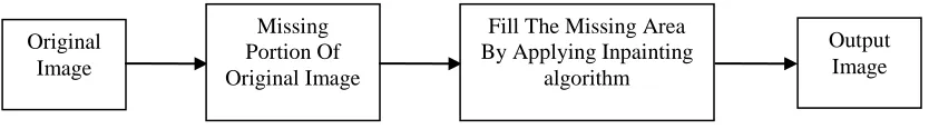
The recent development in internet technologies has made digital media much easier for access. Security issues such as data protection , modification ,forgery, interception have also reached a new level in the internet world. All these factor affect an image by damaging it or modifying it up to certain level. So to avoid this several algorithm have been proposed out of which image inpainting is one method. The main aim of this process [2] is to fill the damaged or missing part of the image based on the information from neighboring areas in such a way that it cannot be found out by an unknown person. Its application includes recovery of ancient films, object elimination in digital images, compression etc. Image inpainting is usefull in application where any modification, damaged portion of an image is unacceptable. Typical example includes biomedical field, satellite system, radar system or any other security related institution. Various methods proposed till now show satisfactory recovery of original image from damaged portion. Figure 1 shows the typical arrangement of image inpainting scheme.
Figure 1: Basic Image Inpainting Process
The rest of the paper is organized as follows. Related work is given in section II. Proposed algorithm with embedding and extraction proceudre are explained in section III. Experimental results are presented in section IV. Concluding remarks are given in section V.
II. RELATED RESEARCH WORK
Lots of research works have been done in image inapainting. The word inpainting was first introduced by M. Bertalmio et al. in 2000 in relation with image restoration as shown in figure 2(a) and figure 2(b) [1]. They suggested
Original Image
Missing Portion Of Original Image
Fill The Missing Area By Applying Inpainting
algorithm
damaged area at the pixel point [2]. This method has the drawback that it produced blur during inpainting process of large region.
Nitin Gopinath et al. given a complex diffusion based algorithm which enhanced both clarity and accuracy by changing the undesired objects from data present in the surrounding pixels [3]. Some researchers have given texture synthesis based inpainting method in which entire picture was searched for the matching neighboring pixels and used it for damaged points but when the picture is large the recovering method takes too much time [6]-[8]. Then another algorithm known as partial differential equation has introduced [10]. It s a differential equation consist of one or more variables, correlating the values of function and its derivative, but fails when missing part is big. To overcome these drawback Lixin Yin et al. has given an algorithm known as exemplar based inpainting which taken into account the isophote shape as a new factor to calculate patch priority and identical cost function [11].
In 2011 Jianbing Yang proposed Total Variant inpainting or TV model in which a precise iterative algorithm to concurrently recognized and recover missing part of an image is explained [12]. This algorithm was unable to reconstruct fractionally damaged images.
Apart from this one more method for reconstructing small area and noise in an image is proposed. Criminisi et al. suggested a approach in this area that connected structural recovery approach with the texture synthesis approach in one algorithm by calculating the advantages of both approaches [16]-[20]. They adopted the fact that the output of inpainting process rely (in general) on the order of filling-in the hole. Also roughness with respect to the structure of the manually selected damaged region is also indicated.
III. Proposed Algorithm
In 2013 Chuan Qin et al. given an algorithm for image inpainting known as curvature driven diffusion model or CDD model [13]. In this, first they applied adaptive reference pixel choosing method in which less reference pixels are chosen in the smooth region and more reference pixels are chosen in the complex region. Then pixel prediction is done by third order partial differential equation to generate inpainted image which has similar structure as cover image.
In our proposed method we have modified Chuan Qin et.al method by choosing equal number of reference pixels from both smooth and complex region. Moreover we have chosen an improved CDD (curvature driven diffusion) based inpainting model instead of partial differential equation based model. The block diagram of proposed system is shown in figure 3.
Figure 3: Block Diagram For Proposed System
2.1. Reference Pixel Choosing Method –
We Denote X(i, j) as the pixel value at the location (i, j) of the Damaged image X sized M × N. Assume that Q is a binary mask image with the similar size as the Damaged image X, which has the locations of reference pixels.
(1)
Where i = 1, 2, . . . , M; j = 1, 2, . . . , N; and μdenotes the interval between the two nearby reference pixels.Based on the above step, we modified the reference pixels according to the characteristics of the damaged image. First, for each pixel P(i, j), where μ + 1 ≤ i ≤ M − μ and μ + 1 ≤j ≤ N − μ, Q0 (i, j) can be updated into Q1(i, j) by
(2)
related to mod (i+j,µ) = 2 where µ is a function with a binary output, i.e., 1 or 0, indicating whether the input pixel X(i,j) belong either smooth or complex. The expression of the function is
E= [X (i-µ,j) + X(i+µ,j) + X(i,j-µ) + X(i,j+µ) – 4 Xmin(i,j,µ)] (4)
Where Xmax(i,j,µ) and Xmin(i,j,µ) are the maximum and minimum value in [X(i-µ,j), X(i+µ,j), X(i,j-µ), X(i,j+µ)] respectively which are nearly equal in our case, and T1 is a predecided threshold. Second, for each pixel x(i',j'), where 1≤i'≤M-µ and 1≤i'≤N-µ, the Q1(i,j) of the pixel belonging to the region i'≤i≤i'+µ, j'≤j≤j'+µ can be further mapped into Q(i,j) if its identical to Q1(i',j'), Q(i'+µ,j), Q(i',j'+µ) and Q(i'+µ,j'+µ) are all equal to 0.
(5)
where 𝜑 is also a function with binary input, i.e., 1 or 0, indicating whether or not region i'≤i≤i'+µ, j'≤j≤j'+µ belongs to the either smooth or complex region, The expression of the function 𝜑 is:
(6)
R= [P (i'-µ,j') + P(i'+µ,j') + P(i',j'-µ) + P(i',j'+µ) – 4 Pmin(i',j',µ)] (7)
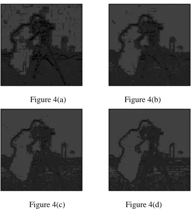
Where Xmax(i',j',µ) and Xmin(i',j',µ) are the maximum and minimum value in [X(i'-µ,j'), X(i'+µ,j'), X(i',j'-µ), X(i',j'+µ)] respectively which is nearly equal in our case, and T2 is a predecided threshold Based upon the equations and condition for reference pixels below are the output image obtained after this process is shown.
Figure 4(a) Figure 4(b)
Figure 4(c) Figure 4(d)
Figure 4 (a) shows the output image at T1 = 2and T2=20, figure 4 (b) shows the output image at T2 = 4 and T = 40, figure 4 (c) shows the output image at T1 = 6 and T2 = 60 and figure 4 (d) shows the output image at T1 =8 and T = 80.
2.1. Image Inpainting Method –
We have applied CDD (Curvature Driven Diffusion) model applied to use the curvature information of the isophotes to handle the curved structures in a better way [14].Our modified CDD model is given by:
(9)
and (.) is the divergence operator. The transfer coefficient [14] of Curvature driven diffusion model is given by equation
(10)
To increase the inpainting time we have seperated coefficient from equation (10) so that the factor
may improves the response time of inpainting process. Secondly, we have introduced mass function
which protects the corners. So the new equation for CDD model is:
(11)
In general, we choose that:
Where x(i,j) is the pixel value of any grad value (i,j)
IV. EXPERIMENT AND RESULT
Experiments were conducted on Output obtained in figure 4 (a), figure 4 (b), figure 4 (c) and figure 4 (d) for image inpainting process given section 2.2 of proposed algorithm.
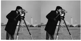
Figure 5(a): Original image (left) and image obtained after improved CDD inpainting process (right) at T1 = 2, T2= 20 (T2= 10×T1)
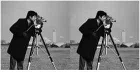
Figure 5(c): Original image (left) and image obtained after improved CDD inpainting process (right) at T1 = 6, T2= 60 (T2= 10×T1)
Figure 5(d): Original image (left) and image obtained after improved CDD inpainting process (right) at T1 = 8, T2= 80 (T2= 10×T1)
Figure 5 (a), Figure 5 (b), Figure 5 (c) and Figure 5 (d) shows the output image or prediction image generated after improved CDD inpainting process. Table I gives a comparison of value of peak to signal noise (PSNR) ratio between Chuan Qin et al. method and proposed method after inpainting process. Also from the table I we can say that our proposed method can achieve better PSNR results.
Table -1 Comparison of PSNR values for Chuan Qin et. al method and proposed method after image inpainting process for figure 5 (a)- (d)
PSNR Values at µ=4
T1 T2 Chuan Qin et al. method Proposed Method
2 20 37.06 dB 46.88 dB
4 40 33.62 dB 45.77 dB
6 60 31.29 dB 45.39 dB
8 80 29.68 dB 45.20 dB
We have also taken some more test images to calculate their PSNR value at different threshold and different values of µ, which can be analyzed from table 2, table 3, table 4and table 5.
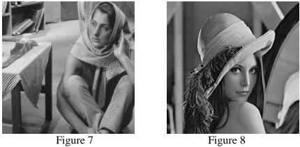
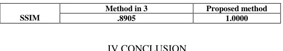
Figure 7 Figure 8
Table -2 PSNR values for proposed method after image inpainting process for different values of µ for figure 6
Threshold
T1 3 5 7 9
T2= T1×10 30 50 70 90
µ = 3 PSNR in db 44.63 43.57 43.19 43.03
µ = 4 PSNR in dB 47.34 46.17 45.70 45.50
Table -3 PSNR values for proposed method after image inpainting process for different values of µ for figure 6
Threshold
T1 3 5 7 9
T2= T1×10 30 50 70 90
µ = 3 PSNR in db 42.82 42.43 42.25 42.13
µ = 4 PSNR in dB 45 44.26 44 43.85
Table -4 PSNR values for proposed method after image inpainting process for different values of µ for figure 7
Threshold
T1 3 5 7 9
T2= T1×10 30 50 70 90
µ = 3 PSNR in db 43.87 43.57 42.19 41.03
µ = 4 PSNR in dB 46.34 45.17 44.70 43.50
Table -5 PSNR values for proposed method after image inpainting process for different values of µ for figure 6
Threshold
T1 3 5 7 9
T2= T1×10 30 50 70 90
Figure 9: PSNR values for various test images for different threshold values
We have also compared the value of the parameter SSIM (Structure Similarity Index Matrix) with the method given in [3]. The Structure Similarity Index Matrix is the method of comparison of two images or the method of measuring of image quality based on an undamaged image as reference [3]. The resultant SSIM is a decimal value between -1 and 1, and value 1
is only achievable in two same sets of information. In our case we have calculated value of SSIM for figure 4 (a), but we can calculate it for any value of T1 and T2. Table 6 gives us the comparison value for SSIM.
SSIM =
Where and are average and variance of and values respectively = (k1 L)×2 , =(k2 L)×2 where L is the dynamic range of pixel values and k1 = 0.01, k2 = 0.02.
Table 6: Comparison of Values of SSIM
SSIM
Method in 3 Proposed method
.8905 1.0000
IV.CONCLUSION
In order to enhance the recovery process of damaged images, an image inpaiting algorithm based on reference pixel choosing method of damaged image has proposed in which nearly equal number of reference pixel are chosen from damaged image. According to the pixel chosen a modified CDD based inpainting method has applied to determine the output image which is quite similar to cover image which was used before damaged. The strategy of choosing reference pixel produced greater possibility for recover of damaged image without much distortion. Experiments were conducted on some gray scale image. Figure 9 shows that the proposed scheme results in better PSNR values for different test images which in turns produced greater possibility of recovering back the undamaged image. Moreover we have also calculated and compared the value of one more parameter called Structure Similarity Index Matrix with method given in [3].
REFERENCES
[1] M.Bertalmio,G.Sapiro, V.Caselles and C.Ballester, "Image inpainting", in Siggraph 2000, Computer Graphics Proceedings, PP.417-424, ACM Press / ACM SIGGRAPH / Addison Wesley Longman, 2000.
[2] Bansi B. Thanki, “Overview of an image inpainting techniques”, International Journal For Technological Research In Engineering, vol.2 ,
issue 5, jan. 2015, pp 388-391.
[4] Weiliang Fan, Jing M. Chen, Weimin Ju, “A Pixel Missing Patch Inpainting Method for Remote Sensing Image”, International Institute for Earth System Sciences, 2011.
[5] Eman T. Hassan_, Hazem M. Abbasy, Hoda K. Mohamed, “Image Inpainting Based on Image Segmentation and Segment Classification”,
IEEE International Conference on Control System, Computing and Engineering, 29 Nov. - 1 Dec. 2013, pp 28-33
[6] Chuang Zhu, Huizhu Jia, Meng Li, Xiaofeng Huang, Xiaodong xie, “Highly Efficient Local Non-Texture Image Inpainting Based on Partial
Differential Equation”, IEEE 17th International Conference on Computational Science and Engineering, 2014, pp 803-807
[7] Abdul R. Zubair,”A Non-Iterative Automated Mechanism for Image Inpainting”, 3rd IEEE International Conference on Adaptive Science
and Technology (ICAST 2011), pp 193-199
[8] Aarti S. Deshmukh, Dr. P. Mukherji,’’Image Inpainting Using Multi resolution Wavelet Transfrom Analysis’’, International Conference
on Communication, Information & Computing Technology (ICCICT), Oct. 19-20,2012, Mumbai, India, pp 1-6.
[9] Mohammad Ali Alavianmehr, Mehdi Rezae, Mohammad Sadegh Helfroush ,Ashkan Tashk,” A lossless data hiding scheme on video raw
data robust against H.264/AVC compression”,
2nd International eConference on Computer and Knowledge Engineering (ICCKE), 2012, page 194-198.
[10] Zhongyu Xu, Xiaoli Lian, Lili Feng,’’ Image Inpainting Algorithm Based on Partial Differential Equation’’, ISECS International
Colloquium on Computing, Communication, Control, and Management,2008, page 120-124
[11] Lixin Yin, Chen Chang,’’ An Effective Exemplar-based Image Inpainting Method’’,IEEE conference on signal and image processing,
2012, pp 739-743.
[12] Jianbin Yang, ‘’ A TV-based Approach On Blind Image Inpainting’’, 4th International Conference On Image And Signal Processing, 2011,
pp 779-781.
[13] Chuan Qin,Ying-Hsuan Huang, and Li-Ting Liao,’’ An Inpainting-Assisted Reversible Steganographic Scheme Using a Histogram Shifting
Mechanism’’, IEEE Transaction On Circuits And Systems For Video Technology, Vol. 23, No. 7, JULY 2013, pp 1109-1118.
[14] Baoyong Yin, Shangping Qiao, Jiansheng Liu, Mingming Li,” The Research and Application of Digital Image Inpainting Based on
Improved CDD model”,International Journal of Computer and Information Technology, Volume 02– Issue 04, July 2013, pp 772-779
[15] Mr. Mahesh Mahajan, Mr. Praveen Bhanodia,“Image Inpainting Techniques for Removal of Object”, ICICES2014 - S.A.Engineering
College, Chennai, Tamil Nadu, India.
[16] A, Criminisi, P. Perez, and K. Toyama, "Region filling and object removal by exemplar-based image inpainting," IEEE Transactions on Image Processing, 2004, 13(9) 1200-1212.
[17] Haibin Wu ,Liquan Wang , Xiaoyang Yu , Hao Bai , Di Wu ‘’Exploration on exemplar-based encoding image inpainting of coded
structured light system’’, 6th International Forum on Strategic Technology (IFOST), 2011, volume 2, pp 1092-1095.
[18] Shu-Chiang ,Chung,Chuan-Pin Lu, Ta-Wen Kuan, Hsin-Yi Lin, ‘’ A New Approach of Image Inpainting Based on PSO Algorithm’’,
International Conference on Orange Technologies (ICOT), 2013, pp 205-209.
[19] Wu Di, Ren Li, Wu Shuang, ‘’Inpaimting Integrated with Decomposition for Image Compression’’, IEEE Advanced Information
Technology, Electronic and Automation Control Conference (IAEAC) , 2015,pp 35-38.
[20] Shyni Shajahan, “Multimode Automatic Image Inpainting”, International Journal of Scientific & Engineering Research, Volume 4, Issue 5,