International Journal of Engineering & Technology IJET-IJENS Vol:16 No:04 26
Substrate Effects on Laminated Glass Window
Kook Chan Ahn
Department of Automotive Engineering, Gyeongnam National University of Science and Technology, Jinju 52725, Korea Telp.: +82-55-751-3641, Fax.: +82 -55-751-3649
e-mail: [email protected] Abstract--Substrate effects on impact behavior of laminated
systems under small mass impact are studied by the coded simulation program. An effective and simple approach connected with a higher-order theory and a generalized power law for layered systems is conducted to analyses substrate effects on laminated glass window. The mechanical properties of the films and substrates are fixed and changed, respectively, and five combinations of substrates and films, namely, ae (=Es/Ef)=0.2, 0.5,
1, 2 and 5 are considered. Impact responses in small ratio (ae =0.2
and 0.5) are more sensitive than those of large ratio (ae =2 and 5)
laminated glass windows. And we can see that unlike results of static analysis, impact responses between interface and impacted surface in case of small ratio are subjected to more failure risk than those of laminated glass windows with large ratio in the same film thickness.
Index Term-- Substrate effect, Laminated glass window, Impacted
surface, Power law
1. INTRODUCTION
The main purpose of the film in laminated glass windows with thin film over the substrate material is to provide absorption to the impact, which puts less stress on the actual substrate. When laminated glass windows are subjected to mass impact that caused by a sufficient heavy and fast impactor, it will break. However, unlike the homogeneous medium that fails in a brittle manner, layered systems can reduce the number of dangerous flying fragments as many fragments will be adhered by the film layer.
The dynamic behaviors of the layered systems under impact loading have been studied in terms of analytical and numerical works [1-3]. However, when a thin film is deposited on a substrate, the deformation and stress field in the resultant laminated glass windows becomes more complex. The Hertz contact law is no longer valid in defining the load-depth response for the indentation of laminated glass windows. It is considered that the critical indentation depends on the mechanical properties of both film and substrate, such as the ratio of the elastic modulus of substrate to that of film, ae
(=Es/Ef). And a detailed study of the influence of the ratio of
the elastic modulus on the film and substrate effects would be very powerful tool for determining the mechanical properties of substrates. For this research, a simple and powerful finite element model connected with Kurapati’s generalized power law is employed to investigate for the substrate effects on laminated glass windows under small mass impact. In other words, the dynamic responses such as history of contact force, energy, strain and stress during impact are obtained and compared with each other among five combinations of
2. NUMERICAL SIMULATION
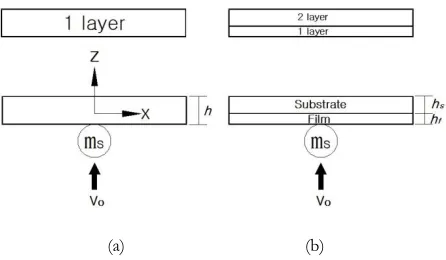
To analysis dynamic behaviors of this laminated glass window, an effective and simple finite element method in conjunction with Sun’ theory [4] and Kurapati’s power law [5] is suggested. Fig. 1 shows schematic diagram of homogeneous medium and laminated glass window. For contact force and indentation relation, Kurapati’s power law using a wide range of film/substrate properties is given as follows
F=CEs (1)
Where F is contact force, δ the indentation, and CEs contact
stiffness. C and p are material constant and power, respectively.
(a) (b)
Fig. 1. Schematic diagram of homogeneous medium and laminated glass window.
It is assumed that a steel ball of diameter 6.35mm impactor and initial impact velocity 10m/s is impacted at the centre of model. The size of model is 100x600mm, film thickness hf=0.4mm and substrate thickness hs=4mm. The mechanical
properties of the film are fixed with elastic modulus, Ef=10GPa. By changing the mechanical properties of the
substrates, various film and substrate combinations (ae=0.2,
0.5, 1, 2, 5) with different ae (=Es/Ef) are considered. The
substrate can be either stiffer (ae>1) or weaker (ae<1) than the
film depending on the value of ae.
Further similar theoretical backgrounds were described in detail in author’s papers [1-3]
3. RESULTS AND DISCUSSION
Fig. 2 depicts the histories of contact force and deflection for laminated glass windows with various ratios of the elastic modulus of substrate to that of film ae. From Fig. 2, the
International Journal of Engineering & Technology IJET-IJENS Vol:16 No:04 27 1.81kN (8μs), 1.68kN (10μs), 1.33kN (15μs) and 0.89kN
(25μs) after the initial impact, respectively. Fig. 3 shows the relation of maximum contact force, contact duration and ratio of elastic modulus of laminated glass windows. From Figs. 2 and 3, it can be seen that the maximum contact force and the deflection in ae=0.2 laminated glass window are much
larger than that of ae=5.0 laminated glass window, whereas
the contact duration in ae=0.2 is much smaller than that of in
ae=5.0. That is, we can see that the harder the material
property of substrate in respect to that of the film (in other words, the softer the material property of film in respect to that of the substrate) is at the same film/substrate thickness, the smaller the maximum contact force and deflection become, but the larger the contact duration becomes.
(a)
(b)
Fig. 2. Histories of (a) contact force and (b) deflection of laminated glass windows.
Fig. 3. Relation of max. contact force, contact duration and ratio of elastic modulus of laminated glass windows.
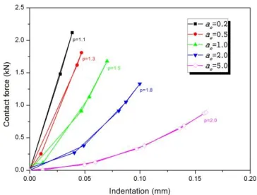
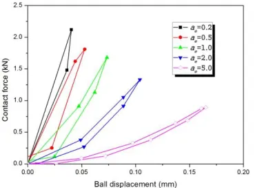
Fig. 4. Relationship of contact force and indentation of laminated glass windows.
Fig. 4 depicts the relationship of contact force and indentation at laminated glass windows. The contact force considers to approach to elastic in the unloading process after it passes the maximum value in the loading process. All of the work done by the impactor on the system in the loading process is the kinetic energy. It can be seen that the corresponding power p=1.5 of ae=1.0 like homogeneous
system (n=1.5) calculated by a power law is consistent with the Hertzian contact law but p=1.1, 1.3, 1.8 and 2.0 of this systems not consistent from Fig. 4. Results of contact stiffness and power by the present study are shown in Table 2. We can see that the larger the value of ae is, the smaller the
International Journal of Engineering & Technology IJET-IJENS Vol:16 No:04 28 Table I
Results of contact stiffness and power by Eq. (1).
System Film/Substrate
Ratio of elastic modulus (ae=Es/Ef)
0.2 0.5 1.0 2.0 5.0
Contact stiffness (CE2,
N/mmp)
0.756E 5
0.948E 5
0.970E 5
0.783E 5
0.347E 5
Power (p) 1.1 1.3 1.5 1.8 2.0
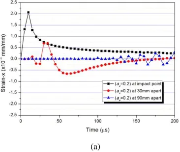
Fig. 5 depicts the dynamic strain histories at the points (0, 30, 90mm apart from the centre) on the surface S3, which is opposite to the impacted surface in the homogeneous medium and laminated glass windows at velocity 10m/s. The strains in the homogeneous medium are larger than those of laminated glass window during the impact event because the film has less stiffness than substrate. In Fig. 5.(a), the first dynamic strain responses of homogeneous medium at 30mm and 90mm apart from the impact point occur at around 9μs and 27μs after the initial impact, respectively. From these results of the dynamic strain responses, the transverse wave velocity becomes 3,333m/s. The transverse wave velocity of homogeneous medium with a single layer by wave propagation theory is 3,394m/s. From this comparison, the present program can be verified by good coincidences between each other. From Fig. 5(b), transverse wave velocity of laminated glass windows with multiple is predicted 375m/s because the first dynamic strain responses at 30mm and 90mm apart from the impact point occur at around 80μs and 240μs after the initial impact, respectively. We can predict that transverse wave velocity of homogeneous medium is much faster than that of laminated glass windows [6].
(a)
(b)
(c)
Fig. 5. The dynamic strain histories of (a) ae=0.2, (b) ae=1.0 and (c) ae=5.0 laminated glass windows at each point on surface S3.
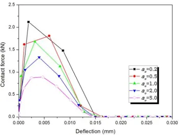
Fig. 6 depicts the relation of contact force and deflection curves on the homogeneous medium and laminated glass windows. It shows that the thickness of substrate at identical film thickness affects so much on the relation of contact force and deflection but the thickness of film at identical substrate thickness has no significant effect, and the maximum deflection does not occur at the maximum contact force. It shows a typical wave-controlled impact that the contact force and deflection are never in phase.
Next, Fig. 7 shows these results for impactor velocity and energy histories in two systems. The velocity and energy at the time zero are the initial velocity and energy at which the impactor hits the target. Velocity curves of Fig. 7(a) decrease and take negative values and remain constant by time. These negative values represent rebound velocity of the impactor. Minimum kinetic energy occurs when velocity is zero in Fig 7(b). The lowest tip of the curve depicts minimum kinetic energy and the end of curve that remains constant depicts the rebound energy at these curves. And, the energy difference between initial energy and rebound energy becomes absorbed energy by target as shown in results of Ref. [3].
International Journal of Engineering & Technology IJET-IJENS Vol:16 No:04 29 the smaller the absorbed energy become. In addition, the
thickness of film at identical substrate thickness does not affect so much on the rebounded and absorbed energies.
Fig. 6. Relationship of contact force and deflection of laminated glass windows.
(a)
(b)
Fig. 7. The (a) velocity and (b) energy histories of laminated glass windows.
Fig. 8. Relationship of energy and ratio of elastic modulus ae of laminated glass windows.
Fig. 9 depicts relationships of contact force and ball displacement of homogeneous medium and laminated glass windows. The rigid impactor hitting the deformable target involves loading and unloading processes. The product of contact force by displacement is the energy of the impactor, thus, the area under these closed curves represents the loading and unloading energy phase, respectively. If energy loss is negligible, the area under the loading curve represents the initial energy (Ei), which is the same as the kinetic energy
at the start of impact. The area under the unloading curve represents the rebound energy (Er). The absorbed energy (Ea)
absorbed during the impact is Ei minus Er and is depicted in
the loop area of the contact force- displacement curve. It may be concluded that the existence of film thickness between homogeneous medium and laminated glass window has significant effect but the thickness of film in layered system does not affect so much on the absorbed energy of target like dynamic characteristics.
Figs. 10 shows the dynamic stress histories through each layer for homogeneous medium and laminated glass windows at impact point and 30mm apart from impact point. S2 and S1 represent the impacted surface of homogeneous medium and laminated glass windows, respectively. S2 in laminated glass window means surface on the substrate and S3 the opposite surface of impact in two systems as shown in Fig. 1. Stresses on the impacted surface S1 of laminated system approach to zero and is smaller than those on the substrate surface S2. Therefore the interface is prone to more failure risk than the other layer.
International Journal of Engineering & Technology IJET-IJENS Vol:16 No:04 30 advances damage from surface S1 to S3 rapidly, as shown in
Ref. [3].
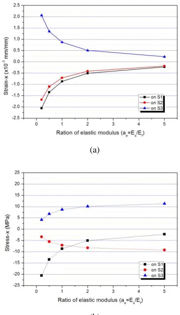
Fig. 12 shows relation of strain and stress verse ratio of elastic modulus ae on each layer of homogeneous and
laminated systems, respectively. When ratio of elastic modulus ae increases under 2.0, strain on surfaces S1 and S2
increases, whereas on surfaces S3 decreases. And, also, when ratio of elastic modulus ae under 2.0 increases, stress on
surfaces S1 and S3 increases but on surfaces S2 decreases. Hence, it can be seen that strain and stress occurred by small mass impact depends on ratio of elastic modulus under ae=2.0 but above ae=2.0 does not affect so much on dynamic
behaviors.
Fig. 9. Relationship of contact force and ball displacement of laminated glass windows.
(a)
(c)
Fig. 10. Dynamic stress histories through the layer of (a) ae=0.2, (b) ae=1.0 and (c) ae=5.0 laminated glass windows on each surface at impact
point.
(a)
(b)
International Journal of Engineering & Technology IJET-IJENS Vol:16 No:04 31
(a)
(b)
Fig. 12. Relationship of (a) strain and (b) stress and ratio of elastic modulus ae on each layer of laminated glass windows.
4. CONCLUSION
A simple and powerful finite element method for dynamic behaviors of laminated glass windows considering substrate effects is simulated. The mechanical properties of the films and substrates are fixed and changed, respectively, and ae =0.2,
0.5, 1, 2 and 5 are considered. Impact responses in small ratio (under ae =2.0) are more sensitive than those of large ratio
(above ae =2.0) laminated systems. And, we can see that
unlike results of static analysis, impact responses between interface and impacted surface in case of small ratio are subjected to more failure risk than those of laminated systems with large ratio in the same film thickness. In other words, it can be seen that strain and stress occurred by small mass impact depends on ratio of elastic modulus under ae=2.0 but
above ae=2.0 does not affect so much on dynamic behaviors.
REFERENCE
[1] Ahn, K. C., “The Dynamic Effect of PVB Interlayer Thickness on Laminated Glass Window”, Int. J. of Engineering & Technology IJET-IJENS, 15(5), pp. 33-40, 2015.
[2] Kim, B. H., Lee, W. B., and Ahn, K. C., “Dynamic Response of Homogeneous and Film/Substrate Systems Subjected to Low Velocity Impact”, Int. J. of Engineering & Technology IJET-IJENS, 15(6), pp. 1-10, 2015.
[3] Lee, T. H., Ahn, K. C., and Kim, B. H., “The Effects of Film/Substrate Properties on Impact Behaviour of Layered Systems”, Int. J. of Engineering & Technology IJET-IJENS, 16(1), pp. 1-8, 2016.
[4]Sun, C. T., and Huang, S. N., “Transverse Impact Problems by Higher Order Beam Finite Element”, Computers & Structures, 5, pp. 297-303, 1975. [5]Kurapati, S.N.V.R.K., Lu, Y. C., and Yang, F., "Indentation
Load-Displacement Relations for the Spherical Indentation of Elastic Film/Substrate Structures”, CMC (Computers, Materials & Contina), 20(10), pp. 1-17, 2010.