Abstract— This research investigated the flow and convective heat transfer characteristics of an impinging synthetic jet with different excitation modes. The synthetic air jet was generated by a vibrating membrane which pushed out the air from the cavity through the exit nozzles with oscillatory motion. The main purpose of this synthetic jet was to create vortices pair to come out from nozzle which will accelerate the heat transfer process occurring at the impinged wall. This heat transfer enhancement principles became the basis to simulate an alternative cooling system to substitute the conventional fan cooling in electronic devices due to its advantage for having a small form factor and low noise. The investigation combined computational and experimental works. The model was simulated to examine the distribution of heat flow on the impinged walls using a turbulent model of k-ω SST. Meshing order was elements Tet/Hybrid and type Tgrid and the number of grid was more than 230 000 in order to ensure detail discretization and more accurate calculation results. In the experiment, sinusoidal and triangular waveform were generated with a function generator to oscillate the membrane. The frequency of membrane vibration were 80 Hz, 120 Hz, 160 Hz and the velocity amplitude was 1 m/s. Some results indicated significant influence of the excitation waveform to the rate of heat transfer obtained.
Index Term— heat transfer, impinging wall, synthetic jet, sinusoidal wave, triangular wave
I. INTRODUCTION
Devices that work based on electricity share one common thing i.e. heat generation. Currently, most common method to overcome this heat is by using cooling devices such as fans and heat sinks. However, the size of electronic devices are getting smaller. Conventional fans have limitation in their dimensions, because the fans operate based on electromagnetic principle which require a minimum space in order to assemble the coil. A synthetic jet is a new technology developed in order to replace fan technology for cooling
This work was supported by RUUI-2010 research grant under contract no. 2604/H2.R12/PPM.00.01/2010/ University of Indonesia.. a Dr. Harinaldi is with the Department of Mechanical Engineering Faculty of Engineering University of Indonesia, Depok, Jawa Barat, 16424, Indonesia (Phone:+62-21-7270032;Fax:+62-21-7270033;e-mail:[email protected]).
b Mr. Damora Rhakasywi is a PhD student at the Department of Mechanical Engineering Faculty of Engineering University of Indonesia;
e-mail: [email protected]
c Mr. Rikko Defriadi is a Master degree student at the Department of Mechanical Engineering Faculty of Engineering University of Indonesia;
e-mail: [email protected]
purpose. It allows cooling effect to perform in a small-size electronic devices and it also has a good efficiency. A synthetic jet works as a jet of vortex generated by the continuous vibration of a diaphragm strong enough to produce flow separation at the outlet of its cavity.
The synthetic jet technology has been developed in many ways in order to find its best performance. Travnicek and Tesar [1] studied synthetic jet characteristic based on its mass transfer effect generated by its flow. They used an impinging method of synthetic jet made of a loud speaker with 100 mm diameters. The loud speaker was mounted to a nozzle in order to generate a vortex. The experiment was conducted with different kind of excitation, such as a high and low frequency. The results concluded that the low excitation tend to make more vortex than the high one. Another investigation conducted in a 2D-computational field using impinging synthetic jet method was done by Jagannatha, et.al [2]. An User Defined Function (UDF) was used to represent the fluctuating velocity of the membrane since the synthetic jet membrane has two phase i.e. suction and discharge. This UDF accurately represented the membrane velocity profile with a positive value (discharge) and negative value (suction).
Heat transfer is a very important aspect in synthetic jet technology since the generated vortices tend to take away the heat. Zhou and Ming [3] conducted an experiment to determine the heat transfer coefficient of an impinging synthetic jet. The investigation used particle image velocimetry, hot-wire anemometer, and infrared camera. The results indicated that the jet exit orifice produced a pair of vortexes that split and join together on a regular basis to form a stable jet in a wide range slots of the channel near the exit hole. Impinging synthetic jet as a promising technology for electronics cooling applications was recently studied focusing on the distribution of heat transfer and flow characteristics from jet sprayed on the surface by blowing with jet diameter of 1-6 mm at the Reynolds number of 1100-4900 [4]. The results obtained showed an agreement between measured average and fluctuating heat transfer distributions and local acceleration. The turbulence intensity along the heated surface tend to increase and support the surface heat transfer when mixing in the wall jet increased and finally split into small-scale turbulence. Travnicek and Tesar [5] suggested that the basic goal in convective transport is to bring the cooling fluids as near as the wall and the synthetic jet impinging method are
Flow and Heat Transfer Characteristics of an
Impinging Synthetic Air Jet under Sinusoidal
and Triangular Wave Forcing
Harinaldi
a, Damora Rhakasywi
band Rikko Defriadi
caffected by the actuator geometry, such as the cavity and the nozzle.
Mostly electronic devices are mounted inside a casing. Chaudhari, et.al [6] conducted an experiment to see the synthetic jet characteristic over a closed environment. In their experiment a ducting system was used in order to make the closed environment. The ducts were mounted on top and below the synthetic jet. There was also a heated block attached in some parts of the lower ducting which was aimed to observe the synthetic jet effect. The result indicated that the synthetic jet could be used in the closed environment, but the suction process tend to retake the heated air that accumulates in the closed environment.
Meanwhile, subsequent investigations by the numerical solution to simulate the model of 3-D impinging synthetic jet have also been carried out by some previous researchers. Gerty et al. [7] conducted computational studies and showed that for power dissipations of 5 W in each area of 27 mm x 38 mm, the velocity field of the active heat sink based of a new air flow design produced thermal resistance of approximately 60% and could reduce thermal resistance by 20%. The results proposed an important design consideration to prevent component failure due to overheating and to improve operational reliability with optimum performance. In this case the synthetic jet model proposed was analyzed by an unsteady solution using Reynolds Average Navier-Stokes (RANS) equations. Another numerical work was conducted by King and Jagannatha [8] on the cooling of electronic devices that deal with the increased heat load associated with higher manufacturing process. In this study, they used OpenFOAM in which the mesh motion was facilitated by applying the appropriate boundary conditions for the displacement at each boundary. The model utilized a two-dimensional synthetic jet with k-ω SST turbulence model to calculate the flow turbulence. Some comparisons of the heat transfer between sinusoidal and non sinusoidal operation showed higher heat transfer about 5 to 10 percent higher for non-sinusoidal results for the range of parameters investigated in this study. In order to define a better waveform forcing on a synthetic jet, statistical analysis using ANOVA method was conducted and the results indicated that each waveform was contributing different effect in synthetic jet effectiveness [9].
In the present work a comprehensive study was done by computational and experimental method on an original design of synthetic jet actuator that operate based on membrane made of piezo material to move the air with the vibrations that occur in this membrane. The main focus of the study was to characterize the convective heat transfer of an impinging flow configuration in a more realistic condition for an application of cooling an electronic device.
II. METHODS
A model of an originally designed synthetic jet actuator (SJA) was used and its detailed dimension is shown in Fig. 1. The arrangement comprises a piezoelectric membrane that is set in motion back and forth forcing fluid inside the cavity to flow through a nozzle which located at the bottom of synthetic
jet. In its inward motion, the membrane imparts the ejected air of high-speed into the surrounding fluid while the retreating membrane draws fluid back from the surroundings into the cavity. The membrane operation over one cycle depends on the selected frequency. The jet delivers very high net outflow of fluid momentum, consequently very intense cooling rates while having no net change of fluid mass within the cavity.
(a)
(b)
Fig. 1. Synthetic jet physical model (dimension in cm) (a) synthetic jet actuator and heat sink arrangement (b) synthetic jet actuator detail
The present investigation was done comprehensively by computational and experimental works in order to elucidate the fundamental mechanism of a synthetic jet in enhancing the cooling effect over a microelectronic component model. The detail of each works are describe in detail as follows.
A.Computational Work
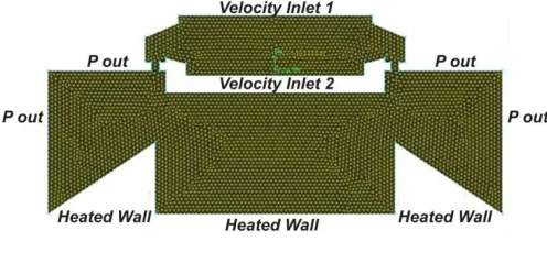
Fig. 2. Computational Domain
The solver software was used to complete the analysis of heat flow field in the synthetic turbulent jet applied a mathematical model of k-ω SST (Shear Stress Transport ). The model use 2D Double Precision model. The SST k-ω model is similar to the standard k- ω model, but includes the following refinements: (i) the standard k-ω model and the transformed k-ε model are both multiplied by a blending function and both models are added together. The blending function is designed to be one in the near-wall region, which activates the standard k-ω model, and zero away from the surface, which activates the transformed k-ε model, (ii) the SST model incorporates a damped cross-diffusion derivative term in the ω equation, (iii) the definition of the turbulent viscosity is modified to account for the transport of the turbulent shear stress and (iv) the modeling constants are different [10]. The SST k-ω model has a similar form to the standard k- ω model as expressed in equations (1) and (2).
~k
i k k
i j j
k
k ku k G Y S
t x x x
(1)
( ) i
i j j
u G Y D S
t x x x
(2)
where the constants :
As the working fluid, air was assumed to be isothermal and incompressible. The thermodynamic properties of air were taken to be at 30 oC under standard atmospheric conditions. The heated wall at the bottom of the domain, where the jet impingement occurs, was maintained at an isothermal temperature of 60 oC. The boundaries on either side of the actuator were treated as constant static pressure outlets with a pressure of one atmosphere. The other details of computation conditions are listed in Table I.
The movement of the diaphragm was modeled with a user defined function that incorporated dynamic layering technique [11]. Segregated solution method with implicit solver formulation was used as the solution algorithm while the
second order discretization schemes were employed for density, momentum, pressure, turbulence kinetic energy, specific dissipation rate and energy.
TABLE I
COMPUTATION CONDITION
In this study, the jet flow occurs in oscillatory manner within a confined region. It is predicted that turbulence would be induced in some regions of the domain while the flow would mostly remain under laminar conditions indicated by low values of the Reynolds number encountered. The parameters used in the simulation include the model settings, fluid properties, and the value of boundary condition.
The iteration was conducted using 1 second of time size. And the time step for iteration is 10, 50 and 120. And the operating condition was 27oC and using 9.81 m/s2 at Y- axis as the gravitational acceleration. The initial (t = 0) position of the diaphragm was taken to be at the bottom of the cavity. The diaphragm motion was assumed to mimic piston movement within a cylinder, which was expressed in (3) for sinusoidal wave and (4) for triangular wave.
0 sin 2
VV A f t (3)
0 2 2
0,1,2,...
sin 2 1 2
8 1 2 1 A A A ft V V A
(4)where A is the maximum velocity (velocity amplitude) generated by the movement of the diaphragm inside the cavity and t is the operational time. Under these conditions, the unsteady, Reynolds-averaged Navier-Stokes equations within the solution domain were solved along with the energy equation for a range of operating conditions.
B.Experimental Work
Experimental work was carried out by measuring the temperature at the heat sink using a digital thermometer with measurement accuracy 0.05 oC in an experimental arrangement as shown in Fig. 3. The heat sink used for the experiment had a circular form with 32 fins, 11 cm of diameter and 5 cm of height. The heat sink was made of cylindrical aluminum which was shaped by using material removal methods. Heat source was obtained from the heater mat placed at the bottom of the heat sink, and it was set to 60
open conditions at ambient temperature of 30 oC More than 7000 individual data were recorded for each measurement run which give estimated statistical uncertainty of 1%. The sinusoidal and triangular wave forcing were generated by a sweep function generator with the frequency of 80 Hz, 120 Hz and 160 Hz using maximum signal setting at 28.8 Volt.
Fig. 3. Experimental Set-up
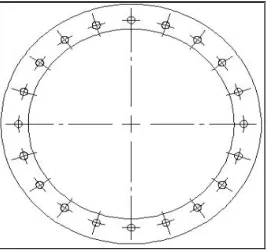
The impinging synthetic jets module used in this study were constructed in the form of a symmetric cylinder cavity with membranes at the top and bottom. The membrane pushed the air inside the cavity to escape into the surrounding air through exits nozzle. The synthetic jet casing was made of nylon material because it was easy to shape and has a good insulator properties. Fig. 4 shows the synthetic jet bottom area which has 20 channels of flow passage. The distance between the channel was 9 mm and the channel diameter was 2 mm.
Fig. 4. Bottom part of synthetic jet actuator
III. RESULTSANDDISCUSSION
A. Instantaneous vorticity contours
Using Eq.(3) and Eq. (4), the UDF model for synthetic jet velocity inlet profile can be acquired by substituting frequency of 80 Hz, 120 Hz, and 160 Hz. The simulation is time dependent because the wave has oscillated velocity. In order to simplify the simulation the flow is examined at the condition of inward motion of the membrane. As shown in Fig. 5, the inward motion amplitude occurs when the signal is at 1/(4x) second where x is the frequency.
Fig. 5. Scheme of waveform for synthetic jet forcing
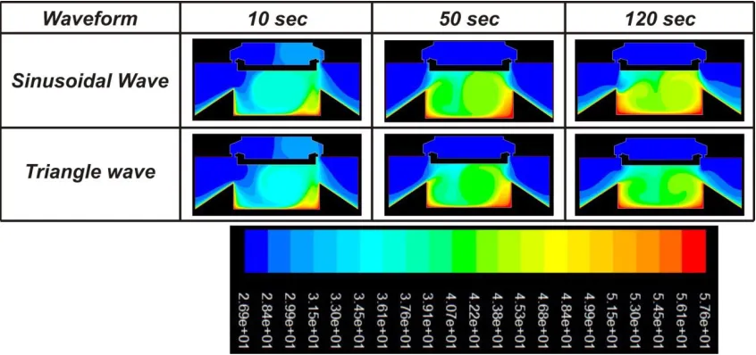
Fig. 6 show a typical vorticity field at some instantaneous times when the synthetic jet is actuated with sinusoidal and triangular wave forcing at 80 Hz. The vorticity magnitude is always changing from time to time. The difference of the magnitude is influenced by the unsteady flow generated by the vibration of the membrane. Movement of the membrane is influenced by the frequency and amplitude values. As indicated in Fig. 6, at 10 seconds after the oscillatory forcing being applied, the vortices start to come out from the cavity through the nozzles and entering the channel space between the synthetic jet module and the heated wall. A closer look at those contours indicates that with a triangular wave forcing the vorticity is larger in magnitude than that produced by a sinusoidal wave. The vorticity is influenced by the sudden enlargement of the channel at the cavity outlet. At 50 second, it can be seen that higher vorticity isformed around the edge for both case of wave mode of forcing. Further at 120 second, the vorticity at both of cases are decreasing significantly.
From this simulation it can be figured out that the generated vortices from the synthetic jet forced by those two different wave mode provides a potential influence to the process of heat transfer in the heat sinks. The vortices can accelerate the process of convective heat transfer that occurs in the channel space between the heat sink and the synthetic jet module.
B.Instantaneous velocity contours
Fig. 6. Instantaneous vorticity contours within solution domain during one diaphragm cycle (1/s) excited at 80 Hz
Fig. 7. velocity magnitude contours within solution domain during one diaphragm cycle (m/s) excited at 80 Hz
C.Instantaneous air temperature contours
Fig. 8 shows the temperature distribution under the influence of impinging synthetic jets at 80 Hz some instantaneous times. The temperature distributions of the heat sink fluctuate following the oscillatory movement of the piezoelectric membrane and as the time proceeds, the temperature is rising. The figure indicates that there is some natural convection occurs due to heated air at the center of the space between the heat sink and the synthetic jet module. Then, the heated air is rising and blown by the synthetic jet air. The air flows smoothly and takes the heat away along the passage of the heat sink which has a drafted shape. In case of sinusoidal wave forcing, Fig. 8 shows that significant temperature decrease occurs during the period from 10 second to 120 second which indicates a good cooling effect. Observation on temperature distribution variation of closer time interval implies that natural convection process also takes place in combinations with the synthetic jet blowing that enhance the cooling process. This coupling effect is more profound in case of the sinusoidal wave forcing. On the other hand with the triangular wave forcing, in first 10 second the heated air enters the cavity of synthetic jet actuator so that the temperature has not much decreased as time proceeds. In this case, the air heated by natural convection is rising into the synthetic jet actuator and being sucked into the cavity that makes the air which is then blown back already contains some heat in it. The heat is then absorbed back by the heat sink, instead of being removed by synthetic jet blows.
D.Experimentally Measured Temperature
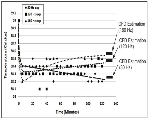
The measurement results of heat sink temperature obtained in an open space conditions within time period of 120 minutes are described in Fig. 9 for the case of sinusoidal wave and Fig. 10 for the case of triangular wave excitation.
Fig. 9. Time history of heat sink temperature under synthetic jet blowing with sinusoidal wave forcing
Fig. 10. Time history of heat sink temperature under synthetic jet blowing with triangular wave forcing
It is clear that the waveform and frequency plays important roles in synthetic jet cooling in both forcing modes of current study. Initially, the synthetic jet is able to reduce the temperature of heat sink. However, as the time progress the heat sink temperature is rising and achieve its constant condition after some period of time. In the figures it is also shown the computational prediction of the stable temperatures of the heat sink. From Fig. 9 and 10 it is obvious that increasing the frequency of oscillation will retard the cooling effect. An excitation with lower frequency will make a lower stable temperature of heat sink. This results seems to be caused by a mechanism in the interaction between membrane oscillation and flow inertia. When the oscillatory membrane move faster up and down in the cavity the air flow cannot perfectly follow the movement due to its inertial effect so that the synthetic jet produce less effective cooling effect. Further indicated at Fig. 10, a not preferred situation with regards to cooling purpose occurs in case of excitation with triangular wave at 160 Hz which make the heat sink temperature rise even slightly higher to its initial condition after a long time operation of the synthetic jet actuator. Here, it seems that the air flow imposes an obstruction effect to the membrane so that it does not have sufficient power to push the air out. Moreover, the sensitivity of varying frequency of excitation to the cooling effect is more significant when forcing the synthetic jet actuator with triangular wave.
Based of the measured temperature, the heat trasfer coefficient can be evaluated as follow:
s j
Q h
A T T
(5)
where Q is the heat transfer rate from the heat sink (W) to the ambient air. Tsis the heat sink temperature (oC) at its constant
state. Tj is ambient temperature (oC) at the measurement
from a heater mat placed at the bottom of the heat sink, then the heat transfer rate can be calculated by conduction formula:
Q = kA T dx
(6)
where k is the thermal conductivity of the heat sink material (W/mK). A is the heat sink total area (m2). T is the heat sink temperature change (oC) and dx is a total effective length (m) of heat sink.
Applying equations (5) and (6) and measured temperature, the calculation results of heat transfer coefficient are shown in Fig. 11 and 12 which describe the time history of heat transfer coefficient during time period of 120 minutes.
Fig. 11. Convective heat transfer coefficient under synthetic jet blowing with sinusoidal wave forcing
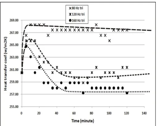
Fig. 12 Convective heat transfer coefficient under synthetic jet blowing with triangular wave forcing
As shown in Fig. 11, in case of forcing with sinusoidal wave the heat transfer coefficients for all frequency of excitation are rising and being relatively constant after some times (about 5 minutes). On the other hand, the heat transfer coefficient with the triangle wave forcing tend to decrease after achieving its maximum value as shown in Fig. 12. This tendency is more significant at higher frequency of excitation. Even at 160 Hz, after about 20 minutes the heat transfer rate is less than its initial condition. It indicates that after some period of giving cooling effect to the heat sink, the synthetic air jet create opposite effect of imposing heating to the heat sink. As discussed before it seems that the air flow imposes an obstruction effect to the membrane so that it does not have sufficient power to push the air out. Hence, instead of blowing low temperature air, the synthetic jet actuator discharges heated air which is drawn back to the cavity at the previous suction phase. The above results indicates that for a heat removal the sinusoidal forcing is more effective than the triangular forcing.
If compared the results of the work conducted by Zhou and Ming [3] especially to the obtained heat transfer coefficient, this prototype has achieved better cooling effect. Zhou and Ming’s study reported a maximum heat transfer coefficient of 95 W/m2K while in the present study the maximum heat transfer coefficient achieved is more than 267 W/m2K.
IV. CONCLUSION
An investigation on the flow and heat transfer characteristics of a synthetic jet generated by using sinusoidal and triangular waveform has been analyzed. A comprehensive study has been done by computational and experimental method on an original design of synthetic jet actuator that operate based on membrane made of piezo material to move the air with the vibrations that occur in this membrane. The oscillation frequency in synthetic jet which describes the number of suction and discharge stroke of the membrane in the cavity in a second obviously plays important role in the heat transfer process. Forcing the synthetic jet with both waveforms at lower frequency will give more remarkable cooling compared to forcing at higher frequency. Furthermore, with regard to cooling purpose, the sinusoidal forcing is more effective for heat removal than the triangular forcing.
Current achievements of the work suggest some improvements need to be address for the future work to develop a synthetic jet with a higher cooling efficiency. These improvements include the asymmetrical cooling effect due of the random effect from the air that blown by the membrane, the actuator range from the heat source, and the possibility of using the different signal wave for the lower and upper membrane.
ACKNOWLEDGMENT
The authors thank to Mr. Kenfery and Mr. Edward for helping the set up of experimentation.
REFERENCES
[2] D. Jagannatha, R. Narayanaswamy, and T.T Chandratilleke, ”Performance Characteristics of A Synthetic Jet Module For Electronic Cooling,” 10th Heat Transfer Conference in International Symposium On phase Change, UK, 2007
[3] Z.J. Zhou and T.X. Ming, ”Experimental Study on Flow and Heat Transfer Characteristics of Synthetic Jet Driven by Piezoelectric Actuator,” Springerlink, vol.50, no.2, pp. 221-229, 2007
[4] A.McGuinn, T. Persoons, P. Valiorgue, T.S. O’Donovan and D.B. Murray, ”Heat Transfer Measurements of an Impinging Synthetic Air Jet With Constant Stroke Length,” The 5th European Thermal Sciences Conference, The Netherlands, 2008.
[5] Z. Travnicek and V. Tesar, ”Pulsating and Synthetic Impinging Jets,”
Journal of Flow Visualization, vol. 8, no. 3, pp.201-208, 2005. [6] M. Chaudhari, B. Puranik, and A. Agrawal, ”Heat Transfer Analysis in a
Rectangular Duct Without and With Cross Flow and an Impinging Synthetic Jet,”. IEEE, vol.33, no.2, pp. 488-49, 2010.
[7] D.Gerty, D.W. Gerlach, Y.K. Joshi, and A.Glezer, ”Development of a Prototype Thermal Management Solution for 3-D Stacked Chip Electronics by Interleaved Solid Spreaders and Synthetic Jets,”
Therminic, EDA Publishing, 2007
[8] A.J.C. King and D. Jagannatha, ”Simulation of Synthetic Jets With Non-Sinusoidal Forcing Functions for Heat Transfer Applications”. 18th World IMACS/MODSIM Congress, Cairns Australia, pp. 1732-1738, 2009.
[9] P. Mane, K. Mossi and R. Bryant, “Synthetic jets with piezoelectric diaphragms,” Smart Structures and Materials 2005: Active Materials: Behavior and Mechanics, edited by William D. Armstrong, Proceedings of SPIE, vol.5761, pp. 233-243, 2005.