International Journal of Engineering & Computer Science IJECS-IJENS Vol:12 No:06 5
Smart Control Techniques based Economic Power
Generation Scheduling
Nadjamuddin Harun *, Tajuddin Waris *, Syafaruddin *,
Takashi Hiyama
**Abstract-- The study aims to gain the benefit of using fuzzy logic system for the economic the scheduling of power generation by means the minimum of the generation cost. The input pattern of the proposed fuzzy logic control is derived from LaGrange method. The fuzzification process ends up with single input and single output system that are valid for all variables. The initial condition of the case power system is analyzed using Newton-Raphson load flow method and the input-output characteristic equations determined by the Least S quare method. The target of generation scheduling is all the thermal power plants connected in the S outh-Sulawesi interconnected system, Indonesia. The simulation results showed increasing in the operational cost efficiency from low to peak loading. In addition, the results related to operational cost and total cost efficiency using this smart control technique are averagely of 4,675.75 Rp/MWh and 23.4 %, respectively; that means better than the merit loading as the conventional technique used in the region.
Index Term-- S mart control, fuzzy logic system, La Grange method, Newton-Raphson method, least-square method, economic scheduling.
I. INTRODUCTION
For the economical operation of power system, the unit generation scheduling is one of the important considerations. It is due to the electrical characteristics of each gen erators connected in the system are different and the variation in load profile is random. In fact, the operation of these generators should be in synchronism and the minimu m cost of total generation must be ach ieved. Fo r this reason, the control to schedule the amount of power generation on each unit is required. This kind of mechanis m needs the e xce llent manage ment of electrica l power system operation for the
optimization purpose (1). In case of thermal power p lant, the
level of minimu m cost can be reached by only imple menting smart scheduling in the corridor of a llo wable electrica l energy quality. It means that while the load profile is difficult to predict and the unit generator should run, the coordinated power output control is very important to ensure the balance between the generation and load for the sake of nomina l frequency system. Due to the variety of daily load, it is necessary to know which generator should be start -up and shut-down in the economic po int of v iews and what is the order. The p rocedure to have proper decision in this problem is
* Department of Electrical Engineering of Universitas Hasanuddin, 90245 Tamalanrea-Makassar, Indonesia
** Department of Computer Science and Electrical Engineering of Kumamoto University, 2-39-1 Kurokami, Kumamoto 860-8555, Japan
commonly operated by the unit commit ment controlled by
different intelligent control technique approaches (2).
Following this condition, the automatic generation control should be developed under steady state point of view. One of the reasonable solutions for the optimized scheduling is the smart control technique by means of fuzzy logic control system. Again, that the fuzzy logic can be useful for the process of uncertain data input, imp recision output and proven to be easy and cheap in the imple mentation level. The application of fuzzy logic control for the economic scheduling of power system is continuously received more
attention (3). One of the reasons of using this method is the
capability to reach the ma ximu m efficiency operation o f power system as a part of our main goal. The economic scheduling is important in all powe r system to gain revenue of our early investment of the system. The achievement in ma ximu m effic iency will reduce the generation cost in kWh in the customer and utility’s side and the cost and of course to reduce the total fuel consumption.
In the economic operation of power system, it can be divided into two ma in considerations. The first one is related to the minimu m cost of power production and the next one is re lated to the min imu m loses in the transmission line. The minimu m cost generation is pretty close to the minimu m fuel cost consumption needed for the overall operation o f system. Fo r this reason, the economic scheduling focuses on the coordinated electric ity production cost of all generators.
Conversely to the minimu m losses during power
transmission, it is highly depending on how the power flo w controlled in the system. Both the economic scheduling and minimu m losses proble ms can be solved conventionally using optima l power flow progra m, where the parameters can be automatically controlled to meet the allowab le marg in of system while minimizing the specific objective function. The classical approach of the econo mic scheduling is to distribute the capacity of the most economic generation unit. In this case the transmission losses are represented by the output function and the variety of generation units. In comparison, the min imu m cost and power delive ry are obtained by scheduling all generator units usin g optima l
power flow based smart control technique (4).
Nowadays, the interconnected operation of power systems is inevitable for the reasons of stability, continuity in power supply within economic consideration. The economic scheduling within interconnected system using sma rt control
technique provide the automatic generation
control to
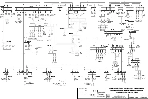
Fig. 1. Single line diagram of our case study system
loading functions as unit commit ment to determine which generator should run and how much the capacity shou ld be generated based on the priority table. This table is made according to the operation cost of each generator per energy generation. The cheapest one is the most priority options. However, with the comple xity of power system increases with the e xistence of independent power producers, the me rit loading is not suitable anymore. One of the ma in constraints in the interconnected system is the highly fluctuated load that must be followed by optimal powe r dispatch. Consequently, the optima l powe r flow changes to minimise the MW output and needs rescheduling. There so many optimization techniques deal with optimal power flo w problem; for instance based dynamic progra mming, linearization as well non-linear approaches and intelligent control.
In this work, the fuzzy logic control system is utilized for smart scheduling of generator systems. The reason for taking the fuzzy logic control technique is to reduce deviation between load and generation under uncertainty condition of power system operation. If the prop osed method is properly worked out, then load distribution by unit generations can be exactly balanced and consequently affected the nominal frequency system stability, reduced
fuel consumption and power losses of system in broad term.
II. CASE STUDY AND PROPOSED SM ART CONTROL
SYSTEM S
Now, we have the good background to understand the economical scheduling that needs the load distribution between generators. For e xa mple , the total output of two generators should balance with load share so that the incre mental fuel cost of one generator is higher than the others. Consequently the load is transferred fro m the higher cost generator to the lower one. Reducing load fro m one unit of generation with high incre mental cost will reduce significant operational cos t of system. The load transfer process is continuously worked until the incre mental cost of
both generators is equal (6). This approach is also suitable for
the system with more than two generators. The point is the economic load sharing between generators must follo w criteria that all units of generator should be operated in the equal incre mental fuel cost. When the incremental fuel cost and all units of generator operate almost linear with assumption of output power in the allo wable range, the
calculation can be much easier (7). For this reason, there
are two considerations for economical scheduling for each
unit of generations, i.e the assumption that the total
output of generator is varied and calculation of the
incremental fuel cost including the characteristic
International Journal of Engineering & Computer Science IJECS-IJENS Vol:12 No:06 7
TABLE I
THERMAL UNIT AVAILABLE IN THE CASE STUDY SYSTEM
Sector
/branch Generation Unit
No. of unit
Output power (MW)
Installed Delivered
Tello, 30 kV
Steam thermal-2 Gas thermal WESTCAN Gas thermal ALSTHOM Diesel MIRRLES 1 1 1 2 12.50 14.47 21.35 5.68 11.5 12.5 15.0 3.0 Tello, 150 kV Diesel MITSUBISHI Diesel SWD Gas thermal GE-1 Gas thermal GE-2
1 1 1 1 12.6 12.4 33.4 33.4 10.5 10.5 33.0 33.0
The proposed of smart controlled system is imp le mented in e lectrica l power system in South Sula wesi, Indonesia. The system consists of 7 centres of power plants with 23 generators, 20 load centres and 27 power transmission lines to connect between the power plant and load centres as shown in Fig. 1. The focus of scheduling is on the non-private therma l power plants, which their capacities
shown in Table I. The system is recognized la rge in the region but the operation procedure still follows the conventional one; i.e by the order of cost of generation fro m
cheapest to the most e xpensive one. This proble m t ries to be solved using smart control technique by means fu zzy logic controller. For this work, the comp lete in formation about the electrica l powe r systems in the region, such as sin gle line diagra m includ ing data transmission system, data of therma l power plant and power flow analysis under several loading condition is modelled in the Matlab simulation environment. To determine the in itia l condition of the system o r norma l
operation, the power flo w progra m based on
Newton-Raphson method is run under several scenarios of loading conditions. The results of this simulat ion as the initia l condition is the voltage, power loses and the phase angle. Based on this information, then we determine the input-output characteristic equation for every generator unit based on the operational cost of generator using Least Square method. The operational cost consists basically of fixed and variable costs. The variable cost is the function of the generator output as shown in Table II. The variable costs can be calculated using input-output characteristics of generator using second order polynomial equation.
The unit commit ment of generation can be expressed as
the optima l decision re lated to the scheduling of start-up and shut-down of the therma l unit in order to reduce the generation cost as long as the reserved margin is enough to
TABLE II
DATA INP UT-OUTP UT OF THERMAL UNIT P LANT IN SOUTH-SULAWESI,INDONESIA
Generation Unit Input Output (MW)
NHR Litre/hour Rp/hour Steam thermal-2 (MFO) 0.446
0.414 0.398 0.375 1282.25 2380.5 3432.75 4312.5 512,900 952,200 1,373.100 1,725,000 2.875 5.75 8.625 11.5 Gas thermal WESTCAN (HSD) 0.878
0.68 0.49 0.452 2743.75 4250 4593.75 5650 1,646,250 2,555,000 2,756,250 3,390,000 3.125 6.25 9.375 12.5 Gas thermal ALSTHOM (HSD) 0.757
0.52 0.442 0.427 2838.75 3900 4972.5 6405 1,703,250 2,340,000 2,983,500 3,843,000 3.75 7.5 11.25 15 Gas thermal GE-1 (HSD) 0.585
0.42 0.359 0.332 4826.25 6930 8885.25 10956 2,895,750 4,158,000 5,331,150 6,573,600 8.25 16.5 24.75 33 Gas thermal GE-2 (HSD) 0.559
0406 0.357 0.329 4611.75 6699 8835.75 10857 2,767,050 4,019,400 5,301,450 6,514,200 8.25 16.5 24.75 33 Diesel MITSUBISHI (MFO) 0.291
0.281 0.225 0.265 763.875 1475.25 1771.88 2782.5 305,550 590,100 708,752 1,113,000 2.625 5.25 7.875 10.5 Diesel SWD (MFO) 0.302
0.292 0.231 0.264 792.75 1533 1819.13 2772 317,100 613,200 727,652 1,108,800 2.625 5.25 7.875 10.5 Diesel MIRRLES (MFO) 0.351
support the system. The p roble m is the wide deviation between the fluctuated load and the generation unit coming to the system. The refore, we need to take some assumptions,
such as the load is constant in one period of time as results
from load estimation, transmission losses is ignored and thermal power reserve has been scheduled. Following these assumptions, the minimization of objective function of unit commitment in terms of fuel cost and start-up cost can be formulated as:
N H SCost H G t F
Cost i i
N H J i i ..., , 2 , 1 ), )} ( { cos ( 1 1
(1)
where Cost is the total cost in one period of time, FCosti is the cost
of generation of unit Gi in hour time H, SCosti is the cost during
start-up generation of unit Gi, while N and J is the time interval
(period).
With constraint criteria, the balance between generation and load is obtained as follows.
J i iN
H
H
L
H
G
1...,
,
2
,
1
;
)
(
)
(
(2) where Gi(H) is total power generation of unit Gi in hour time H andL(H) is the load power consumption during H period. The margin of generation capacity is defined as:
N
H
P
P
P
min
iH
max;
1
,
2
,
...,
(3) where Pm in is the minimum generation capacity of unit i, Pm ax is themaximum generation capacity of unit i and PiH is the power
generated of unit i in hour time H.
M eanwhile, the margin of spinning reserve is defined as follows:
J i iHN
H
H
R
H
L
S
P
1 max...,
,
2
,
1
;
)
(
)
(
(4)where SiH is the status of unit i (either ON or OFF), R(H) is the
allowable power reserve in hour time H and L(H) is the load in hour time H.
According to the unit commitment objective function in (1), it is necessary to determine the fuel cost Fcost(H,J) in all operating
conditions as representation of the total cost. This fuel cost is determined by economic operation of on-line units at J condition in time hour H. The objective function to minimize this fuel cost is expressed as:
J
i i i
G
F
J
H
Cost
1)
(
)
,
(
(5) where Fi(Gi) is the fuel cost of unit i and usually expressed inquadratic equation as:
i i i i i i
i
G
a
G
b
G
c
F
(
)
(
)
2
(6) with the constraints are shown in (2) and (3). In this respect, the Lagrange method is enough to give solution for the problems mentioned above.For scheduling purpose with m order of generation unit, Eq. (6) is the objective function that needs to be minimised in this proposed work and the equation is modified into:
m m m m m
m
a
P
b
P
c
F
2
(7)where m is the order of plant mth; am, bm and cm are the constant
characteristic of each generator, Pm is the total output of generator
and the Fm is the variable cost.
In addition, the calculation of Incremental Fuel Rate (IFR), Net Heat Rate (NHR) and efficiency for the system can be solved using the following equations:
) / (litre MWh dp
dH IFR
i i
(8)
In order to determine the heat rate and the fuel consumption for thermal power plant, we need to use the equation of Net Heat Rate (NHR) as follows:
)
(
/
MW
Output
hour
litre
Input
NHR
(9)It can be seen from eq. (9) that NHR is basically similar to the efficiency calculation shown in (10):
%
100
x
Input
Output
Efficiency
(10) Conventionally, the heat rate ratio is inversely proportional to the fuel efficiency consumption. For this reason, the lower heat rate represents the higher efficiency of fuel consumption (8). Themaximum efficiency can be reached at the total output generator in our system around 116.5 M W, which requires fuel efficiency consumption for about 31%. The demand of fuel for specific generation output can be easily converted into Rupiah/M Wh (note: Rupiah= Indonesian currency). In this respect, the load distribution amongst generator is equivalent to the increase or decrease in the total cost. Therefore, the incremental fuel cost can be obtained from the slope input-output curve between two unit generators. It means that the increase in fuel cost consumption is the differential function of fuel cost at certain generator to the total output (9). The increase in fuel cost consumption at definite output power can be considered as the additional cost in Rp/hour for every 1 M W. The complete data input-output of thermal power plant in the case study system is available in Table II.
Implementing the Eq. (7) into the case study system is very important. Based on the characteristic of each unit of generator, it is obtained the input-output equations for 8 different types of thermal generation unit exist in the system, including the fuel cost and incremental fuel cost. These equations are tabulated in Table III.
Then, the generation units can be grouped based on the voltage level connection and the thermal type. Therefore, the cost equivalent of input-output related to the fuel cost and incremental fuel cost following Table III above is summarized in Table IV.
International Journal of Engineering & Computer Science IJECS-IJENS Vol:12 No:06 9
Fig. 2. Schematic diagram of developed fuzzy logic control system
SWD a re a lways operated during peak load; therefore they have me mbership degree of 1 in fuzzy logic control, means not the target for the schematic control development.
Based on the optimal scheduling results in Table V, the load range can be determined and considered as the input variable for the set of developed fuzzy system. However, the
optimized result cannot still guarantee the economic generation in overall operation conditions. Therefore , the optimization results using Lagrange method is just some kind of pattern for the smart control of fuzzy logic system.
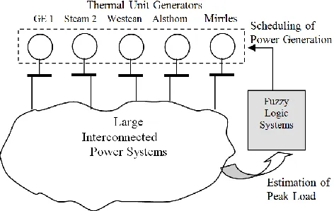
The developed fuzzy logic control system has structure with single input and single output (SISO). The schemat ic diagra m can be seen in Figure 2. The input variable is the therma l load information supplied load by 5 units of therma l
generator;Gas thermal GE-1, Stea m therma l-2, Gas therma l
WESTCAN, Gas therma l A LSTHOM and Diesel MIRRLES, while the output variable is the economic dispatched load supplied by these units. The peak load information fro m the load center is obtained and processed by implication rules. Only 5 units of thermal generator is optimized in this respect due to the other 3 units is constantly supply during peak load.
TABLE III
INP UT-OUTP UT EQUATIONS INCLUDING FUEL AND INCREMENTAL FUEL COSTS OF THERMAL UNITS
Generation Unit Input-output equation (Hi) in Litre/hour Fuel cost equation (Fi) in (Rp/hour) Incremental fuel cost (IFC) (Rp/MWh)
Steam thermal-2 Gas thermal WESTCAN Gas thermal ALSTHOM Diesel MIRRLES Diesel MITSUBISHI Diesel SWD Gas thermal GE-1 Gas thermal GE-2
43.125+447.8P -6.6087P2 1480.1+470.2P -11.5P2
2050.3+190.1P +6.6P2 61.3125+174.5P +41.33P2 484.3438+99.4807P +10.8588P2 439.0250+135.8526P +7.7141P2
2772+251.6P -0.1P2 2450.3+263P -0.2P2
17250+179120P -2643.5P2 888060+282120P -6900P2 1230180+114060P +3960P2
24525+69800P +16532P2 193738+39792.3P +4343.52P2
175610+54341P +3085.64P2 1663200+150960P -60P2 1470180+157800P -120P2
17920-5287P 282120-13800P
114060+7920P 69800+33063P 39792.3+8687.04P
54341+6171.28P 150960-120P 157800-240P
TABLE IV
EQUIVALENT EQUATIONS OF FUEL COST AND INCREMENTAL FUEL COST
Thermal type and location Fuel cost equation (Fi) in (Rp/hour) Incremental fuel cost (IFC) (Rp/MWh)
Tello 150kV, Gas thermal Tello 150kV, Diesel Tello 30kV
3198360+153240P -40P2 362225.2+48298.32P +40P2 381800.1+359755P -4757.38P2
153240-80P 48298.32-3608.09P
359755-9514.76P
TABLE V
ECONOMIC DISPATCH OF THERMAL UNITS USING LAGRANGE METHOD
Load
Gas thermal, 150 kV Diesel, 150kV Tello, 30kV
GE-1 GE-2 Mitsubishi SWD Steam thermal-2
Gas thermal WESTCAN
Gas thermal ALSTHOM
Diesel MIRRLES 124.00
122.50 114.75 107.00 99.25 91.50 90.00
33 33 33 30.7592 23.0738 15.3885 13.901
33 33 33 33 33 33 33
10.5 10.5 10.5 10.5 10.5 10.5 10.5
10.5 10.5 10.5 10.5 10.5 10.5 10.5
11.5 11 7.747 5.5004 5.4842 5.468 5.4425
12.5 12 10.98 9.606 9.59 9.5745 9.5489
10 8.5 6.01 4.64 4.623 4.607 4.5815
Fig. 3. Smart control technique of fuzzy logic system (SCT –FL)
Fig. 4. Membership functions of input variable
TABLE VI
LINGUISTIC VARIABLES AND MEMBERSHIP FUNCTION FOR INP UT DATA VARIABLE
No Linguistic variables LOW (MW)
MED (MW)
HIGH (MW)
1 NSMALL 90 91.5 99.25
2 SMALL 91.5 99.25 107
3 MEDIUM 99.25 107 114.75
4 BIG 107 114.75 122.5
5 P BIG 114.75 122.5 124
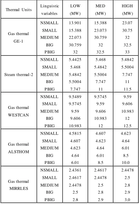
TABLE VII
LINGUISTIC VARIABLES AND MEMBERSHIP FUNCTION FOR OUTP UT DATA VARIABLE OF THERMAL UNITS
Thermal Units Linguistic variables
LOW (MW)
MED (MW)
HIGH (MW)
Gas thermal GE-1
NSMALL SMALL MEDIUM
BIG P BIG
13.901 15.388 22.073 30.759 32
15.388 23.073 30.759 32 32.5
23.07 30.75 32 32.5
33
Steam thermal-2
NSMALL SMALL MEDIUM
BIG P BIG
5.4425 5.468 5.4842 5.5004 7.747
5.468 5.4842 5.5004 7.747 11
5.4842 5.5004 7.747
11 11.5
Gas thermal WESTCAN
NSMALL SMALL MEDIUM
BIG P BIG
9.5489 9.5745 9.59 9.606 10.983
9.5745 9.59 9.606 10.983 12
9.59 9.606 10.983
12 12.5
Gas thermal ALSTHOM
NSMALL SMALL MEDIUM
BIG P BIG
4.5815 4.607 4.623 4.64 6.01
4.607 4.623 4.64 6.01 8.5
4.623 4.64 6.01 8.5 10.0
Gas thermal MIRRLES
NSMALL SMALL MEDIUM
BIG P BIG
2.4361 2.4617 2.4478 2.5 2.8
2.4617 2.4478 2.5 2.8 2.9
2.4478 2.5 2.8 2.9 3.0
It is we ll known that a fu zzy logic controlle r is a c losed circ le system; means there is not operator in any parts of controlled circ le system as shown in Fig. 3. Basically, the output variable is feedback to the input signal through process in the sensor system and then to be compared with reference value. If the error is high, the input variables of
system (E) should be mapped into fuzzy singleton in the
linguistic parts contains fuzzification interface (FI).
Furthermore, this process is continued to decision ma king
logic (DML) that should produce fuzzy conclusion as the
control action. This action is basically obtained by
evaluating number of fuzzy rules (k nowledge base) for each
fuzzified input. In the output part, defuzzificat ion interface
(DFI)is a part ofthe last step to draw the fuzzy conclusion.
This part includes giving heavy and combination of several fuzzy set that giving crisp fuzzy singleton fro m each output.
The detail e xplanation about the fuzzy design system is explained as follows.
The fu zzy control system design fo llo ws three important stages, i.e fu zzification, fu zzy inference, defuzzification stages. In the beginning in the fuzzificat ion stage (initia l strategy), the me mbership function of input and output variable are made overlap. This is to ensure that all crisp values are inc luded in the e xisting sets and to make possible that more than one rule involved in determin ing output. In this case, we comb ine the triangle shape and half-trapeziu m to represent the input variable. There are five fu zzy
variables, i.e NSMA LL, SMA LL, M EDIUM、BIG and
PBIG as linguistic variable for input-output data. The input me mbe rship degree is utilized as functional defin ition where
a trapeziu m shape is considered for the 1st and nth
me mbe rship function and a triangle shape is for the 2ndto
(n-1)th me mbe rship function. For instance, the nth
me mbe rship function is a triangle function that consists of a,
b and c values, represents as LOW, M EDIUM, and HIGH
values. The LOW value fro m the (n-1) me mbership function
must take the MEDIUM va lue fro m the (n-2) me mbership
function, as well as the HIGH va lue must take M EDIUM
value fro m n me mbership function. In th is respect, the
MEDIUM va lue is HIGH va lue fro m me mbership function
(n-2) and could also be a LOW value fro m n me mbership
value. This approach can be seen in Fig. 4.
It is necessary to bring our approach to our study system in the case of controlling the output of therma l generator. In this case, the objective function that needs to be optimized is the cost generation function within constraint function of electrica l load balanc ing supplied fro m a ll therma l generator
units. Following the assumption in Fig. 4, the linguistic
variable for input me mbership function is defined from the
International Journal of Engineering & Computer Science IJECS-IJENS Vol:12 No:06 11
TABLE VIII
IF-T HEN RULES FOR THERMAL GENERATION OP ERATION CONTROL
IF Load THEN Thermal P ower P lant VERY LOW NSMALL
LOW SMALL
MEDIUM MEDIUM
HIGH BIG
VERY HIGH P BIG
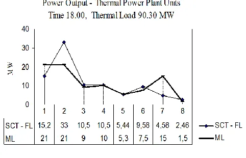
Fig. 5. Smart control technique of fuzzy logic system (SCT –FL) Descriptions:
1 = GE-1, 2 = GE-2, 3 = MIT SUBISHI, 4 = SWD, 5 = Steam thermal-2, 6 = WEST CAN, 7 = ALSHT OM,
8 = MIRRLES
the linguistic variable for output membership function defined by five thermal units, such as Gas thermal GE-1, Stea m
therma l-2, Gas therma l W ESTCAN, Gas therma l
ALSTHOM and Gas thermal MIRRLES is shown Table VII. In the fuzzy inference stage or coordination strategy, it is
important to calculate the fire strength that ma kes it possible for the case study system by means to provide and fulfill determined rules. The rules obtained for th e thermal generation operation control shown in Tab le VIII. Fina lly, in the the defuzzificat ion stage, it needs to convert the linguistic variab les to numerical variables (crisp value) of the output variables. In th is case, the method of Center of
Area (COA) or centre of gravity is defined for the
defuzzificat ion stage. The general equation for the defuzzificat ion stage using COA method is stated in (11) as
follows:
M
k R k
M
k R k k
z
z
z
z
1 1
)
(
*
)
(
(11)
where R(zk) is the centre of gravity of each output
me mbe rship function, zk is the respective output variable
and z is the output signal.
The results for these approaches make the output generation can be optimized within minimu m cost during load change period.
III. SIM ULATION RESULTS AND DISCUSSION
Practica lly in our case study system like other power systems, the load profile always fluctuates. In fact, it is difficult to predict the a mount of load changes due to some unknown factors. In order to ma intain the frequency stability, it is necessary to have coordinated output power control to balance between the load and generation. In this point, economic generation scheduling needs to be performed using fuzzy logic systems. The economic scheduling application itself involves the analysis procedure based on the electric ity data input and the generation characteristics (10).
It has been mentioned in the previous section that our study is focused on the non-private thermal powe r plants interconnected in the South Sulawesi System. Currently, we
have total of 8 units therma l powe r p lants, specified by their fuel types, i.e Gas thermal GE-1 (HSD), Gas thermal GE-2 (HSD), Diesel MITSUBISHI (M FO), Diesel SW D (MFO), Steam thermal-2 (MFO), Gas therma l WESTCAN (HSD), Gas therma l A LSTHOM (HSD), Diesel MIRRLES (MFO). The complete data can be seen in Table II previously. The price for different type of fuels in the running year found
that HSD (High Speed Diesel) is Rp. 600.00/liter and MFO
(Marine Fuel Oil) is Rp. 400.00/liter. The other characteristics of the systems are the thermal units of GE-2, MITSUBISHI and SWD must generate power at the ma ximu m rate during peak load time . For th is reason, these three units are not using our proposed smart control systems. The typical peak load period analysed in this study fro m 6 p.m. to 8 p.m. within the range of load for therma l generation is between 90.3MW and 120.3MW.
The generation scheduling using proposed smart control at 6 p m is shown in Fig. 5. The total heavy load which must be supplied by all thermal power plants are 90.3 MW, comprises of GE-1 is 15.2 MW, GE-2 is 33MW, MITSUBISHI is 10.5 MW, while 10.5MW for SW D; 5.44 MW for Stea m therma l- 2; 9.58 MW for WESTCAN; 4.58 MW for ALSTHOM and 2.46 MW for MIRRLES. In this figure a lso, we can also obtain the load distribution of each generator using the me rit loading approach. In general, the fuzzy log ic control system can provide ma ximu m load
distribution better than using the conventional method.
The arrangement of generation scheduling uses smart
The strength point of the smart control load distribution results is coming fro m the input pattern created by La Grange method. Th is method is again helping us to select automatically the therma l plant units with certain heavy load that must be giving priority. La Grange function is necessary to establish the required condition for an extre me value of the objective function, to add the constraint function related to the objective function after constraint function has been mu ltip lied by an undetermined mu ltip lie r. If the total therma l load reaches the set point between 90.3MW and 120.3MW, the optimal scheduling control for all e xisting therma l units operate. As results, at 6p m, the gas therma l unit GE-1, which connected to 150 kV and it has capacity of 33MW contribute power supply to the system of 1 5.2MW. The ma ximu m a mount of powe r supply for control actions is designed based on the input pattern derived fro m La Grange method. The method gives limitation to the highest generation level of 33 MW for load capacity between 114.75MW and 124MW, while the lowest of 13.9MW for load capacity of 90MW. The steam thermal-2 of 30 kV, 11.5MW is able to supply power of 9.58, which very close to the ma ximu m rating output. In this case, the limitat ion of control for load range is set ma xima lly at 11.50 MW in the load capability of 124 MW and min ima lly at 5.44MW for load capacity of 90MW. The same approach for gas thermal WESTCAN, 30 kV is able to supply power generation of 9.58MW. The limitation of this unit is 12.5MW for the highest load capability of 124 MW and 9.54 fo r the lowest for load capacity of 90 MW. In case of gas thermal unit A LSTHOM, 30 kV supplies 4.58 MW with capacity 10 MW. Control range for this unit is 4.58MW and 10MW for load capac ity of 90MW and 124MW, respectively. The diesel unit of MIRRLES, 30 kV supplies 2.46 MW. This unit is the lowest capacity (3 MW) in the system, but it can contribute power generation at peak load with output control limitation from 2.43MW to 3 MW.
The next scenario is the result of scheduling control for
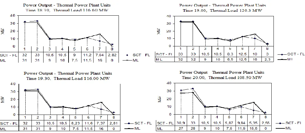
another period between 6.30p m and 8p m. The load distribution for econo mic scheduling of each generation units is shown in Fig. 6. During the observed time period , the power generation is mostly supply at 7pm (e xcept, the steam therma l unit 2 produce high at 6.30p m for about 9). The gas thermal GE-1 is 33MW, W ESTCA N is 12.5MW, ALSTHOM is 10MW and MIRRLES is 3MW. The cause for these conditions is the highest thermal load ca me to the system at 7p m; therefore most therma l units produce power on their ma ximu m capac ities with output control comes fro m set pattern. Again, the proposed method (SCT-FL) can show much better improve ment in terms of ma ximu m powe r generation achieved during certain periods of time compared with the merit loading methods.
In terms of optimization and operational cost related to the effic iency using sing SCT-FL Techniqueis shown in Table IX. It can be seen that our proposed method results is not far fro m the results using merit loading approach. Meanwhile, there is significant improve ment in terms o f operational cost efficiency using fuzzy log ic system based economic scheduling control. This cost efficiency is obtained from the fuel cost equation in Rp/hour for each unit, where init ially forming input-output equation in Liter/hour, then processed using the Least Squared method. The equation resulted from this approach is then multip lied with fuel price fo r each unit. Finally, there is increasing effic iency between 16 and 28 percent during the period of peak loading in the system.
Thermal plant scheduling cons ists of 5 units, two units are using MFO fuel (Stea m therma l unit 2 and MIRRLES), while others consume HSD fuel (GE-1, W ESTCA N and ALSTHOM). In the lowest load thermal (90.3MW), a lmost each thermal unit operated far fro m their capacity, such as GE-1 supplies 15.2MW fro m its capacity of 33MW; the therma l unit-2 supplies 5.44MW fro m its capacity of 11.5MW. On the other hand, for power generation units which use MFO fuel (steam therma l unit 2 and MIRRLES)
Fig. 6. Load distribution on thermal plant units time between 6.30pm and 8pm for every 30 minutes using smart control fuzzy logic system (SCT-FL) and merit loading methods
Descriptions:
International Journal of Engineering & Computer Science IJECS-IJENS Vol:12 No:06 13
TABLE IX
OP TIMIZATION RESULTS AND OP ERATIONAL COST EFFICIENCY USING FUZZY LOGIC SYSTEM SMART CONTROL TECHNIQUE
Load (MW)
Operational Cost (Rp./MWh) Cost Efficiency
Scheduling (ML)
Optimization
(SCT-FL) (Rp/MWh)
P ercentage (%)
90.30 210,142.90 206,760.86 3,382.04 16.094 116.60 197,157.21 191,560.23 5,596.98 28.388 120.30 195,157.41 192,111.52 3,302.90 16.902
116.00 198,176.99 192,567.54 5,609.45 28.305 108.50 201,170.98 195,683.59 5,487.39 27.277
produce less power. These factors cause low operational cost effic iency to about 16%. Meanwhile, when the load therma l reaches 116.6MW, the overall system yields the highest operational cost efficiency of 28.4%. The highest effic iency achievement is due to the contribution of each generating units operate at their ma ximu m capacity, especially for generation unit based MFO fue l. In this case, the big load must be supplied automatically fro m each unit following the output scheduling control. In addition, Tab le IX p rovides the information about the minimu m cost generation after imple menting the smart control technique. Again, our proposed method can offer a meaningfu l
effic iency in terms of operational cost of therma l generator units the case study system.
IV. CONCLUSION
This paper has investigated the important feature of fuzzy logic control system for economic scheduling of powe r system in South Sulawesi, Indonesia under norma l loading conditions. The simulat ion results showed increasing in the operational cost effic iency fro m lo w to pea k loading. In addition, the results re lated to operational cost and total cost effic iency using this smart control technique are averagely of 4,675.75 Rp/MWh and 23.4 %, respectively; that means better than the me rit loading as the conventional technique used in the region. In the end, we can see that the fu zzy logic control system is simple r, more accurate and can be automatically scheduled to achieve economical scheduling, compared to that of conventional method based graphical analysis and analytics, such as merit loading technique.
REFERENCES
(1) C.A. Roa-Sepulveda, M. Herrera, B. Pavez-Lazo, U.G. Knight, A.H. Coonick, ‘Economic dispatch using fuzzy decision trees’, Electric Power Systems Research, 66(2), 2003, pp. 115-122 (2) C. Srinivasa Rao, S. Siva Nagaraju, P. Sangameswara Raju,
‘Automatic generation control of TCPS based hydrothermal system under open market scenario: A fuzzy logic approach’, International Journal of Electrical Power & Energy Systems, 31(7–8), 2009, pp. 315-322
(3) İlhan Kocaarslan, Ertuğrul Çam, ‘Fuzzy logic controller in interconnected electrical power systems for load-frequency control’, International Journal of Electrical Power & Energy Systems, 27 (8), 2005, pp. 542-549
(4) M.K. El-Sherbiny, G. El-Saady, Ali M. Youse,’ Efficient fuzzy logic load–frequency controller’, Energy Conversion and Management, 43(14), 2002, pp. 1853-1863
(5) A. Demiroren, E. Yesil , ‘Automatic generation control with fuzzy logic controllers in the power system including SMES units’, International Journal of Electrical Power & Energy Systems, 26(4), 2004, pp.291-305
(6) Dusmanta Kumar Mohanta, Pradip Kumar Sadhu, R. Chakrabarti, ‘Fuzzy reliability evaluation of captive power plant maintenance scheduling incorporating uncertain forced outage rate and load representation’, Electric Power Systems Research, 72 (1), 2004, pp. 73-84
(7) F. Cziesla, G. Tsataronis, Iterative exergoeconomic evaluation and improvement of thermal power plants using fuzzy inference systems’, Energy Conversion and Management, 43 (9-12), 2002, pp.1537-1548
(8) A. Sanchez-Lopez, G. Arroyo-Fiqueroa, A. Villavicencio-Ramirez, ‘Advanced Control algorithms for steam temperature regulation of thermal power plants’, International Journal of Electrical Power & Energy Systems, 26(10), 2004, pp.779-785
(9) Ilhan Kocaarslan, Ertugrul Cam, Hasan Tiryaki, ‘A fuzzy logic controller application for thermal power plants’, Energy Conversion and Management, 47 (4), 2006, pp.442-458
(10) A.L. Elshafei, K.A. El-Metwally, A.A. Shaltou, ‘A variable-structure adaptive fuzzy-logic stabilizer for single and multi-machine power systems’, Control Engineering Practice, 13(4), 2005, pp. 413-423
Nadjamuddin Harun is a professor in Department of Electrical Engineering of Universitas Hasanuddin, Indonesia. His current research interests mainly in economic dispatching, economic scheduling , steam thermal power generation and application of fuzzy logic controller.
Tajuddin Waris is lecturer and researcher in power system area in Department of Electrical Engineering, Universitas Hasanuddin, Indonesia
Syafaruddin
received his B.Eng degree in Electrical Engineering from Universitas Hasanuddin, Indonesia, in 1996, M.Eng degree in Electrical Engineering from University of Queensland, Australia, in 2004 and D.Eng degree from Kumamoto University, Japan in 2009. He was working in Kumamoto University as a visiting assistant professor for Graduate School of Science and Technology. His research interests include distributed generation planning, maximum power point tracking control of photovoltaic system, power system real-time simulation and neuro-fuzzy logic control application in power system.
Takashi Hiyama received his B.E., M.S., and