e-ISSN: 2278-067X, p-ISSN: 2278-800X, www.ijerd.com
Volume 11, Issue 03 (March 2015), PP.17-25
Methods for Reducing the Activity Switching Factor
Antony Johnson Chenginimattom, Don P John
M.Tech Student, Met’s School Of Engineering, Calicut Univrsity, Kerala, India. Assist. Professor, Met’s School Of Engineering, Calicut Univrsity, Kerala, India.Abstract:- Multiplexing parallel busses into serial links has been proposed for its advantages such as reducing inter connect area, coupling capacitance and crosstalk. But serialization increases bit transition which increases the activity switching factor and power dissipation. Many coding schemes have been proposed to optimize the activity switching factor which is a result of increased number of bit transitions. This paper compares some of the techniques which are used to reduce the activity switching factor and the power dissipation. This paper gives an overview of the bus invert coding, the weight based bus invert coding, the partial bus invert coding, the serialized low energy transmission coding, the transition inversion coding, and the embedded transition inversion coding. The advantages and disadvantages of each technique are compared and the best among them is found to be embedded transition inversion coding.
Keywords:- activity switching factor, word length.
I.
INTRODUCTION
With the advancement of technology, continues scaling of silicon technology became popular which made way for system on chip design to be practical. With the advent of technology the use of system on chip design has increased drastically. The system on chip design has gained mass acceptance in the field of large scale design. The system on chip design deals with the integration of millions of transistors into a single chip.
The two main constraints for the system on chip design process are the limited area of the chip in which the system have to be implemented and the power dissipation parameter. The designers then had a task ahead them which was to find a trade-off between these factors and come up with an optimized scenario where the area can be reduced along with the power dissipation parameter. They proposed many alternatives for solving the same and one among them was to multiplex parallel busses into serial links.
The process of multiplexing parallel busses into serial links deals with the replacement of parallel busses which occupy larger area by serial links. The serialization process reduces inter connect area, coupling capacitance and crosstalk which was a cause of concern in parallel buses. But still there are certain parameters associated with the serialization process like the activity switching factor and the power dissipation that has to be addressed while multiplexing the parallel busses into serial links before it can be implemented in the system on chip design. The activity switching factor and the power dissipation increases during the process of serialization. The activity switching factor tends to increase with the increase in bit transitions. This paper compares some of the most popular techniques developed by various scientists for addressing the increase in activity switching factor and the power dissipation due to the same.
II.
COMPARED TECHNIQUES
This paper compares some of the techniques which are used to reduce the activity switching factor and the power dissipation. In this chapter we discuss about the bus invert coding, the weight based bus invert coding, the partial bus invert coding, the serialized low energy transmission coding, the transition inversion coding, and the embedded transition inversion coding.
A. Bus Invert Coding
There are several steps involved in the bus invert coding technique, they are
Computing the Hamming distance-The Hamming distance gives the information about the intensity by which the present bus value and the next data value differ. Hamming distance is computed. The number of bits by which the present bus value and the next data value differ is calculated using the Hamming distance. The present invert bus value is also counted as a bit.
The term n stands for the word length. Now the hamming distance measure is compared with the word length by two (n/2).
If the hamming distance is greater than the word length by two (n/2) then the invert bus value is set as “1”. When the invert bus value is “1” then the next bus value will be equal to the inverted next data value.
If the hamming distance is smaller than the word length by two (n/2) then the invert bus value is set as “0”. When the invert bus value is “0” then the next bus value will be equal to the next data value.
The bus value will be then transmitted over to the receiver side.
At the receiver side the data is demodulated according to the state of the invert line. The invert line gives information about whether the data is inverted or not.
The set of bits that are shown below (a) are a random set of bits that are to be transmitted through a set of bus lines. The bus invert coding method is implemented on them so as to reduce the activity switching factor. On applying the bus invert coding an extra bus called the invert bus is used. The sequences (b) are obtained on applying bus invert coding method.
D0: 1000010011011000 D1:1000010101101100 D2:0110010100010011 D3:1111000011000010 D4:0001100001110010 D5: 0101010110011001 D6:1100111000101001 D7:1100010110010010
D0: 1000000100110101 D1: 1000000010000001 D2: 0110000011111110 D3: 1111010100101111 D4: 0001110110011111 D5: 0101000001110100 D6: 1100101111000100 D7: 1100000001111111 Inv: 0000010111101101
(a)Random set of bits to be transmitted (b) Set of bits on applying bus invert coding.
B. Weight Based Bus Invert Coding
The weight based bus invert coding technique is an advanced bus invert coding technique. The weight based bus invert coding technique aims to reduce the number of ones being transmitted through a bus. The weight based bus invert coding technique reduces the number of bit transitions. The weight based bus invert coding is similar to the bus invert coding method. The term data value corresponds to the information bit or the data bit to be transmitted, the term bus value corresponds to the information or the data through the bus and the term weight of data (w) which corresponds to the number of ones in a data value sequence. As in the bus invert coding technique here in the weight based bus invert coding technique we use an extra bus which is called the invert bus. The invert bus either have a value ”0” which means the bus value will be equal to the data bit or a value “1” which means that the bus value will have a compliment value of the data bit. The value of the invert line is transmitted to the receiver side at all instances.
There are several steps involved in the weight based bus invert coding technique, they are
Compute the weight of the data sequence (w)-The weight of the data sequence is computed. The weight of the data sequence is nothing but the number of ones in the sequence. The weight based bus invert coding technique reduces the number of ones through the bus.
The term n stands for the word length. Now the weight of the data sequence is compared with the word length by two (n/2).
If the weight of the data sequence is greater than the word length by two (n/2) then the invert bus value is set as “1”. When the invert bus value is “1” then the next bus value will be equal to the inverted next data value.
If the weight of the data sequence is smaller than the word length by two (n/2) then the invert bus value is set as “0”. When the invert bus value is “0” then the next bus value will be equal to the next data value.
The bus value will be then transmitted over to the receiver side.
The set of bits that are shown below (a) are a random set of bits that are to be transmitted through a set of bus lines. The weight based bus invert coding technique is implemented on them so as to reduce the activity switching factor. On applying the weight based bus invert coding technique an extra bus called the invert bus is used. The sequences (b) are obtained on applying weight based bus invert coding method.
D0: 1000010011011000 D1:1000010101101100 D2:0110010100010011 D3:1111000011000010 D4:0001100001110010 D5: 0101010110011001 D6:1100111000101001 D7:1100010110010010
D0: 0100000011001000 D1: 0100000101111100 D2: 1010000100000011 D3: 0011010011010010 D4: 1101110001100010 D5: 1001000110001000 D6: 0000101000111001 D7: 0000000110000011 Inv: 1100010000010000
(a)Random set of bits to be transmitted (b) Bits on applying weight based BI coding.
C. Partial Bus Invert Coding
The partial bus invert coding technique is an advanced bus invert coding technique. The partial bus invert coding technique aims to minimize the number of buses involved in bus coding. The partial bus invert coding technique enhances the reduction of overhead and also reduces the number of bit transitions. The term data value corresponds to the information bit or the data bit to be transmitted, the term bus value corresponds to the information or the data through the bus. As in the bus invert coding technique here in the partial bus invert coding technique we use an extra bus which is called the invert bus. The invert bus either have a value ”0” which means the bus value will be equal to the data bit or a value “1” which means that the bus value will have a compliment value of the data bit. The value of the invert line is transmitted to the receiver side at all instances.
There are several steps involved in the partial bus invert coding technique, they are
Computing the Hamming distance-The Hamming distance gives the information about the intensity by which the present bus value and the next data value differ. Hamming distance is computed. The number of bits by which the present bus value and the next data value differ is calculated using the Hamming distance. The present invert bus value is also counted as a bit.
The term n stands for the word length. Now the hamming distance measured is compared with the word length by two (n/2).
If the hamming distance is smaller than the word length by two (n/2) then the invert bus value is set as “0”. When the invert bus value is “0” then the next bus value will be equal to the next data value.
If the hamming distance is greater than the word length by two (n/2) then the invert bus value is set as “1”. It’s at this phase the partial bus invert coding technique differs from the conventional bus invert coding technique. In partial bus invert coding technique only m bits out of n are inverted so that the total number of transitions is reduced leaving the rest n-m bits un-inverted.
The bus value will be then transmitted over to the receiver side.
At the receiver side the data is demodulated according to the state of the invert line.
The invert line gives information about whether the data is inverted or not.
Let the set of buses be denoted as B throughwhich n number of bits are to be transmitted. In partial bus invert coding technique the set of bus B is partitioned into two sub buses. The partitioning is done based on the behaviour of patterns transmitted through them. The bus B is partitioned into a selected set of sub buses denoted as S with m number of bits and a set with the rest of the sub buses denoted as R with n-m number of bits. The selected sub buses S with m number of bits have higher transition correlation and higher transition probability. The sub buses denoted as R with n-m number of bits are the remaining bus lines. They have low correlation and have lower transition probability. Inverting the sub buses denoted as R with n-m number of bits may increase the transition activity. Hence in partial bus invert coding technique only the sub buses S with m number of bits are inverted. The bus invert coding is applied partially only on the selected sub buses S with m number of bits. On applying the partial bus invert coding technique the hardware overhead and the number of transitions has reduced further.
D. Serialized Low Energy Transition Coding
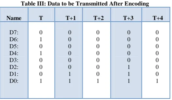
energy is achieved by minimizing the number of bit transitions through a bus and by minimizing the number of ones being transmitted through a bus. In SILENT coding scheme the parallel data bits on different buses are encoded and then serialized before transmission. The XOR operation is employed to encode and decode the data in the SILENT coding scheme. During the encoding process the present data bit and previous data bit is give as the inputs to a XOR gate. The output from the XOR gate is the encoded data bit. This process is done on all bit sequence to be transmitted. Once encoding is done the bit sequence is serialized and transmitted. The example shown below shows how the number of transitions and the number of ones through the bus are reduced using the SILENT coding.
Table I: Data to be Transmitted
Name T T+1 T+2 T+3 T+4
D7: D6: D5: D4: D3: D2: D1: D0: 0 1 0 1 0 0 0 1 0 1 0 1 0 0 1 0 0 1 0 1 0 0 1 1 0 1 0 1 0 1 0 0 0 1 0 1 0 1 0 1
Table II: Serial data without encoding
Time Serial data
no of transitions T T+1 T+2 T+3 T+4 0 0 0 0 0 1 1 1 1 1 0 0 0 0 0 1 1 1 1 1 0 0 0 0 0 0 0 0 1 1 0 1 1 0 0 1 0 1 0 1 5 7 7 5 7
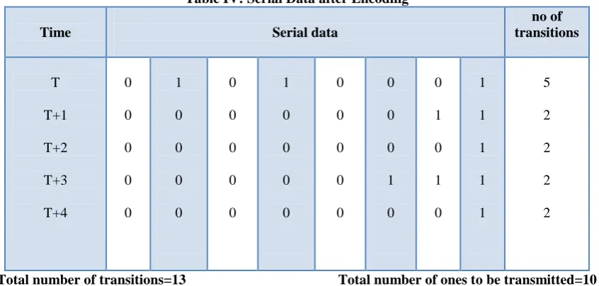
Total number of transitions=31 Total number of ones to be transmitted=17
Table III: Data to be Transmitted After Encoding
Name T T+1 T+2 T+3 T+4
Table IV: Serial Data after Encoding
Time Serial data
no of transitions
T
T+1
T+2
T+3
T+4
0
0
0
0
0
1
0
0
0
0
0
0
0
0
0
1
0
0
0
0
0
0
0
0
0
0
0
0
1
0 0
1
0
1
0 1
1
1
1
1
5
2
2
2
2
Total number of transitions=13 Total number of ones to be transmitted=10
Once the data bits are received at the receiver, deserialization process is done. Now in order to retrieve the original data bits from the sender an XOR operation is employed. The presently received bit which is the encoded bit along with the previously decoded bit is given as the inputs to an XOR gate. The output of the gate gives the original data from the sender.
E. Transition Inversion Coding
The transition inversion coding (TIC) scheme aims to reduce the number of transitions in a bit stream to be transmitted through a bus. The transition inversion coding scheme reduces the energy consumption by reducing the total number of bit transitions and also reduces the activity switching factor. The total number of bits in a bit stream is referred to as the word length of a bit stream and is denoted as W. The term threshold value denoted as N corresponds to a value equal to the word length by two (N=W/2). The transition inversion coding scheme uses an extra indication signal called as transition inversion information indication bit denoted as
Bex. The transition inversion information indication bit is transmitted through a bus called the transition
inversion indication bus.
The transition inversion indication bit will either be a “0” or a “1”. When the data bits in the bit stream are inverted so as to reduce the number of bit transitions the value of the transition inversion indication bit is set as “1” and when data bits in the bit stream are not inverted the value of the transition inversion indication bit is set as “0”.
The transition inversion indication bit value is transmitted at all instances. The transition inversion indication bit is utilized at the receiver to reproduce the original signal from the sender.
There are several steps involved in the transition inversion coding, they are
The number of transitions in a given bit sequence is calculated.
The term W stands for the word length. Now the number of transitions calculated is compared with the threshold value (N) whose value is word length by two.
If the number of transitions is smaller than the threshold value (N) then transition inversion information indication bit denoted as Bex is set as “0”. When the as transition Bex is “0” then the bus value will be
same as the data value which means the data is not inverted.
If number of transitions is larger than the threshold value (N) then transition inversion information indication bit denoted as Bex is set as “1”. When the as transition inversion information indication bit (Bex)
is “1” then the bus value will be the inverted data value which means the data is inverted.
The transition inversion information indication bit (Bex) is transmitted over to the receiver side.
At the receiver side the data is demodulated according to the value of Bex. The invert line gives
F. Embedded Transition Inversion Coding
The embedded transition inversion (ETI) coding scheme is proposed to solve the issue of the extra indication bit. This scheme eliminates the need of sending an extra bit by embedding the inversion information in the phase difference between the clock and the data.
When there is an inversion in the data word, a phase difference is generated between the clock and data. Otherwise, the data word remains unchanged and there is no phase difference between the clock and the data. This ETI coding scheme reduces transitions compared with the other coding schemes. The receiver side adopts a phase detector (PD) to detect whether the received data word has been encoded or not. The embedded transition inversion coding employs hogge phase detector.
The word length is defined as the number of bits in a data word and is denoted as W. The term threshold value denoted as N corresponds to a value equal to the word length by two (N=W/2). A transition is defined as a bit changing from zero to one or from one to zero. For example, the bit stream “0100” has two transitions while “0101” has three transitions. When the number of transitions in a data word exceeds the threshold N, the bits in the data word should be encoded. Otherwise, the data word remains the same. This method checks every two-bit in the data word as shown in Figure 1.
Every two bit in the serial stream is combined as a base to be encoded. When the number of transitions in a data word is less than N, b1b2 remains unchanged. Otherwise, the inversion coding and the phase coding are
performed. For the phase coding, the inversion information is embedded in the phase difference between the clock and the encoded data.
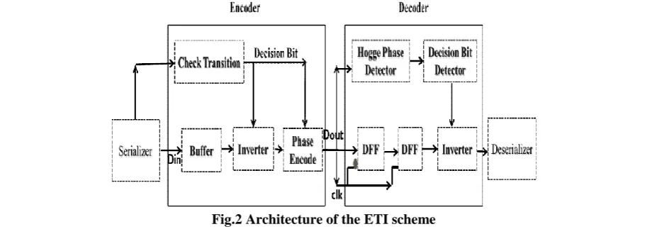
Fig .1 ETI coding scheme for one serial link
The overall architecture of the ETI scheme is shown in Figure 2. The architecture of the ETI scheme has two blocks they are an encoder block and a decoder block. The ETI encoder part decides whether the encoding process or the inversion process is necessary for a particular bit sequence with the help of the check transition block and then produces a decision bit as shown in the figure 2. The decision bit can be either “0” or “1”. If the decision bit is “0” then the input data along with the clock is transmitted to the receiver side.
If the decision bit is “1” then the input data is given to the invert block and the data and clock is made to be out of phase with each other at the phase encoder block. Then the along with the clock is transmitted to the receiver side. In the embedded transition inversion coding scheme ETI decoder part decides whether the encoding process or the inversion process has occurred for a particular bit sequence by using a hogge phase detector. With the help of a hogge phase detector the decision bit is reproduced at the receiver bit as shown in the figure 2. The decision bit can be either “0” or “1”. If the decision bit is “0” then the input data was not encoded at the time of transmission. If the decision bit is “1” then the input data was encoded at the time of transmission.
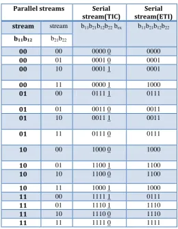
Table V: All Combinations Of Two Bit Streams For The Tic And Eti Coding Schemes
All the possible combinations of a two bit sequence for the transition inversion coding (TIC) scheme and embedded transition inversion (ETI) coding scheme is shown in Table V. The TIC coding uses an extra bit when compared to the ETI scheme. The total number of bits required to be transmitted is reduced in ETI scheme. The energy dissipation is also reduced as the bit transitions are reduced.
III.
RESULT AND DISCUSSION
The Table VI gives an overall idea about what we have come across in this paper. The different coding schemes and the main theory behind each scheme are mentioned in the table. The number of buses required by each coding scheme is given in the table. The coding scheme with the best results is found to be the embedded transition inversion coding.
Parallel streams Serial stream(TIC)
Serial stream(ETI) stream stream b11b21b12b22 bex b11b21b12b22
b11b12 b21b22
00 00 0000 0 0000
00 01 0001 0 0001
00 10 0001 1 0001
00 11 0000 1 1000
01 00 0111 1 0111
01 01 0011 0 0011
01 10 0011 1 0011
01 11 0111 0 0111
10 00 1000 0 1000
10 01 1100 1 1100
10 10 1100 0 1100
10 11 1000 1 1000
11 00 1111 1 0111
11 01 1110 1 1110
11 10 1110 0 1110
Table VI: Comparison Table comparing the important aspects in the Coding Schemes
Coding Scheme Overview on Coding Scheme
Number of buses for N
bits
Power Dissipation(PD)
Comparison to Un-encoded data
Bus Invert Coding Encoded using Hamming distance of data bits
N+1 PD reduces by 50%
Wight Based Bus Invert coding Encoded using Weight of data bits number of 1’s
N+1 PD reduces by 63%
Partial Bus Invert Coding Encoded Partially based on Hamming distance
N+1 PD reduces by 71.8% SILENT Coding Scheme Encoding and decoding using a
XOR operation
N+1 PD reduces by 77%
Transition Inversion Coding Encoding based on the relation between number of transitions and threshold value
N+1 PD reduces. The Transitions reduces by 31.8% Embedded Transition Inversion
Coding
Encoding based on the relation between number of transitions and threshold value and using a phase encoder
N More efficient than the other schemes. PD and transitions reduces
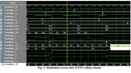
The simulation screen shot of ETI coding scheme is show in Figure.3. The bit combinations are encoded as shown in table V for each corresponding input. The decoding process of the ETI coding scheme is also depicted in the screen shot provided.
Fig .3. Simulation screen shot of ETI coding scheme
IV.
CONCLUSIONS
REFERENCES
[1]. M. R. Stan and W. P. Burleson, “Bus-invert coding for low-power I/O,” IEEE Trans. Very Large Scale Integr. (VLSI) Syst., vol. 3, no. 1, pp. 49–58, Mar. 1995.
[2]. R. B. Lin and C. M. Tsai, “Weight-based bus-invert coding for lowpower applications,” in Proc. Int. Conf. VLSI Design, Jan. 2002, pp. 121–125.
[3]. Y. Shin, S. I. Chae, and K. Choi, “Partial bus-invert coding for power optimization of application-specific systems,” IEEE Trans. Very Large Scale Integr. (VLSI) Syst., vol. 9, no. 2, pp. 377–383, Apr. 2001.
[4]. K. Lee, S. J. Lee, and H. J. Yoo, “SILENT: Serialized low energy transmission coding for on-chip interconnection networks,” in Proc. IEEE Int. Conf. Comput.-Aided Design Conf., Nov. 2004, pp.448– 451.
[5]. R. Abinesh, R. Bharghava, and M. B. Srinivas, “Transition inversion based low power data coding scheme for synchronous serial communication,” in Proc. IEEE Comput. Soc. Annu. Symp. VLSI Conf., May2009,pp.103–108.
[6]. Ching-Te Chiu, Wen-Chih Huang, Chih-Hsing Lin, Wei-Chih Lai, and Ying-Fang Tsao, “Embedded Transition Inversion Coding With Low Switching Activity for Serial Links,” in Proc. IEEE Workshop Signal-Process.Syst.Conf.,Oct-2013,.pp.4408–41.
[7]. H. Kuo, W. B. Wu, Y. J. Wu, and J. H. Lin, “Serial low power bus coding for VLSI,” in Proc. IEEE Int. Conf. Commun., Circuits Syst.,Jun. 2006, pp. 2449–2453.
[8]. S. Zogopoulos and W. Namgoong, “High-speed single-ended parallel link based on three-level differential encoding,” IEEE J. Solid-State Circuits, vol. 44, no. 2, pp. 549–558, Feb. 2009.
[9]. S. R. Sridhara and N. R. Shanbhag, “Coding for reliable on-chip buses: A class of fundamental bounds and practical codes,” IEEE Trans. Comput.- Aided Design Integr. Circuits Syst., vol. 26, no. 5, pp. 977–983, May 2007.