DEVELOPING THE STEAM TURBINE BLADES
BY USING VARIOUS MATERIALS INSTEAD
OF EXISTING ONE AND CONDUCTING THE
STRESS ANALYSIS
Silambarasan.M
1and Arivazhagan.K
2I. INTRODUCTION
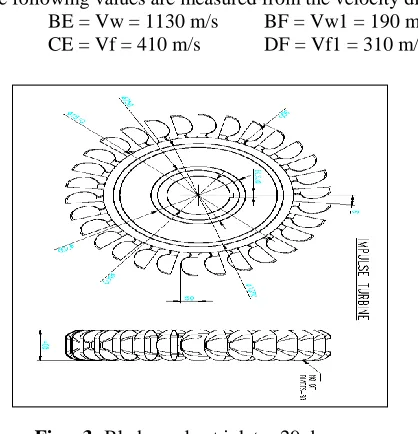
A steam turbine is a prime mover in which rotary motion is obtained by the gradual change of momentum of the steam. In a steam turbine the force exerted on the blades is due to the velocity of the steam. This is due to the fact the curved blades by changing the direction of steam receive a force or impulse. The action of steam in this case is said to be dynamic. Thus the dynamical pressure of steam rotates the vanes, buckets or blades directly. The turbine blades are curved in such a way that the steam directed upon them enters without shock though there is always some losses of energy by the friction upon the surface of blades. In general a steam turbine essentially consists of a following two parts.
NOZZLE
The nozzle in which the heat energy of high pressure steam is converted into kinetic energy. So that the steam issues from the nozzle with a very high velocity.
BLADES
The blades which change the direction of steam issuing from the nozzle so that a force acts on the blades due to change of momentum and propel them. Thus the basic principle of operation of a steam turbine is the generation of high velocity steam jet by the expansion of high pressure steam and then conversion of kinetic energy so obtained into mechanical work on rotor blades. Some aspects of the steam turbine cycle employed in such plants are also included. Sometimes the major role of a steam plant is to supply process steam and electric power is only a by-product or vice versa. Unlike power plant turbines the low output industrial turbines can be made smaller in size by increasing the rotational speeds. In doing so they may require reduction gear boxes for certain applications. Fig -1: Layout of Steam Power Plant.
1
Assistant Professor, Department of Mechanical Engineering Shreenivasa Engineering College, Dharmapuri, Tamilnadu, India
2
Assistant Professor, Department of Mechanical Engineering Shreenivasa Engineering College ,Dharmapuri ,Tamilnadu, India
International Journal of Latest Trends in Engineering and Technology
Vol.(8)Issue(2), pp.358-366
DOI: http://dx.doi.org/10.21172/1.82.049
e-ISSN:2278-621X
Abstract- A steam turbine is a prime mover in which rotary motion is obtained by the gradual change of
momentum of the steam. In a steam turbine the force extracted on the blades is due to the velocity of the steam. This is due to the fact the curved blades by changing the direction of the steam receive a force or impulse. The action of steam in this case is said to be dynamic. As a consequence of the significant amount of time spent away from the design point, the result of negligible pressure drop across the rotor is no longer valid and an appreciable axial force is present. Finite element stress analysis results must also be evaluated, but the fact that stress analysis is so much more. It may be noted that, considering the thermal analysis carried out on the different materials which shows the heat losses due to transfer must be less so that total heat is fully converted to mechanical energy; this may causes the increases in percentage of output power.II. LITERATURE SURVEY
G.G.sozhamanan, S.Balasivanandhaprabhu, V.S.K. Venkatagalapathi
.
Conventional stir casting process hasbeen employed for producing discontinuous particle reinforced metal matrix, composites for decades. The major problem of this process is to obtain sufficient wetting of particle by liquid metal and to get a homogenous dispersion of the ceramic particle. In the present study, aluminum metal matrix composites were fabricated by different processing temperatures with different holding time to understand the influence of process parameters on the distribution of particle in the matrix and resultant mechanical properties. The distribution is examined by micro structure analysis, hardness distribution and density distribution. Aluminum metal matrix composites (MMCs) with Al-7075 matrix reinforced with Al2O3 particulates were prepared by liquid metallurgy route of stir casting. A 2-level factorial design of experiments (DOE) was used to study the influence of process parameter like size and weight fraction of reinforcement, sintering temperature and sintering time on micro hardness and impact strength of the composites. Mathematical model were developed to investigate which parameter significantly affects the selected mechanical properties. The results of the study indicate the both micro – hardness and impact strength Al-7075/ Al2O3 composites are affected by individual parameters as well as their 2-factor interaction. These models can be used to select the optimum process parameter for obtaining composites possessing desired hardness and impact strength within the range of experimental frame work. However, more detailed investigation undertaken by the authors to gain a deeper insight into the behavior of these composites.
Aluminum alloy-based metal matrix composites (AMMCs) have been by now established them as a suitable wear resistant material especially for sliding wear applications. However, in actual practice engineering components usually encounter combination of wear type. An attempt has been made in the present paper to highlight the effect of dispersing sic in 2014 base alloy adopting the liquid metallurgy root on different modes like sliding, abrasion, erosion and combination of wear mode like cavation erosion, erosion abrasion, sliding abrasion and the results obtained compared with the base alloy. It is found that there are a no of contributing factors for the resulting wear and all are not necessarily derogatory in nature. The limits within which the AMMCs can exhibit superior performance over the base alloy have been discussed. Worn surfaces and the subsurface studies have been out to understand the mechanism of material removal and role the different contributing factors to material removal. Wear mechanism that have been prevalent have been suggested and the possibility of making wear resistant components from MMCs is discussed based on the experimental results obtained.
III. AIMS AND SCOPE OF WORK
It is an important loss in both the impulse and reaction turbines, which occurs when the steam glides over the blades. This loss takes place due to friction of the surface of blades. As a result of the blade friction the relative velocity of the steam is reduced while gliding over the blade. Moisture loss is a loss in both the turbines which takes place due to moisture present in the steam. This loss occurs when the steam passing through the lower stages, becomes wet. The velocity of water particles is less than that of steam. As a result of this the steam has to drag the water particles, which reduce the kinetic energy of the steam.
The ultimate purpose of this study is to reduce the losses by replacing the different materials for blades of Impulse turbine with for Therefore, as the starting point, it was decided to use four different materials for turbine blades. The blades were manufactured using FDM Rapid prototyping machine using materials like austenitic alloy, Titanium alloy, Plastic Reinforced Carbon and 304 stainless steel. Before going for this type of manufacturing technique, a detailed stress, thermal and fatigue analysis was carried out for above mentioned materials. This paper reports the findings of those analyses, which provided the base for the manufacture of blades.
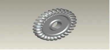
Fig – 2: Blades
IV. DESIGN OF BLADE MATERIALS
4.1 SPECIFICATIONS OF IMPULSE TURBINE
a. Rated Power = 75 KWb. Rated Speed = 2400 rpm
c. Steam Flow Rate = 1500 Tonnes/Hr d. Type = Impulse
e. No of Stages = Single
f. Temperature of Steam = 537° C g. Ampient Temperature = 40° C
The given data for calculating the velocity and driving force of the wheel is given as follows.
Velocity of the steam = 1200 m/s Nozzle angle = 20 degree Blade velocity = 375 m/s Blade velocity coefficient = 0.75 Mass flow = m = 0.5 kg/s
First of all draw a horizontal line and cut off AB equal to 375 m/s to some suitable scale representing the velocity of the blade. Now at b draw a line BC at an angle of 20 degree and cut off BC equal to 1200 m/s to the scale to represent the velocity of steam jet entering the blade.
The following values are measured from the velocity diagram. BE = Vw = 1130 m/s BF = Vw1 = 190 m/s CE = Vf = 410 m/s DF = Vf1 = 310 m/s
Fig – 3: Blade angle at inlet = 29 degree. Fig – 4: Velocity diagram for impulse turbine
4.2 PROPERTIES OF THE BLADE MATERIALS
Table -1: Mechanical properties
Mechanical Properties
Austenitic Alloy
Titanium Alloy
Plastic Reinforced
Carbon
304 Stainless
Table -2: Thermal properties
V. FINITE ELEMENT ANALYSIS
Finite Element Analysis (FEA) is a computer-based numerical technique for calculating the strength and behavior of engineering structures. It can be used to calculate deflection, stress, vibration, buckling behavior and many other phenomena. It also can be used to analyze either small or large- scale deflection under loading or applied displacement. It uses a numerical technique called the finite element method (FEM). The primary unknowns in this structural analysis are displacements and other quantities, such as strains, stresses, and reaction forces, are then derived from the nodal displacements.
5.1. Modeling linear layered shell
The Part Modeling Help introduces you to the terminology, basic design concepts, and procedures that you must know before you start building a part. Part Modeling shows you how to draft a 2D conceptual layout, create precise geometry using basic geometric entities, and dimension and constrain your geometry. You can learn how to build a 3D parametric part from a 2D sketch by combining basic and advanced features, such as extrusions, sweeps, cuts, holes, slots, and rounds. Finally, Part Modeling Help provides procedures for modifying part features and resolving failures.
Fig – 5: Modelling linear layered shell
The Finite Element Method (FEM) is a reliable numerical technique for analyzing engineering designs. FEM replaces a complex problem with many simple problems. It divides the model into many small pieces of simple shapes called elements. Elements share common points called nodes. The behavior of these elements is
well-TENSILE STRENGTH
(Pa)
758XE+6 220XE+6 120XE+6 505XE+6
Thermal Properties
Austenit ic Alloy
Titaniu m Alloy
Plastic Reinforced
Carbon
304 Stainless Steel
THEMAL CONDUC-TIVITY (W/m-K)
17.3 7.10 24.3 16.2
SPECIFIC HEAT
the X, Y, and Z directions. These are called degrees of freedom (DOFs). Analysis using FEM is called Finite Element Analysis (FEA).
5.2. Static Analysis
A static analysis result of structural displacements, stresses and strains and forces in structures for components caused by loads will give a clear idea about whether the structure or components will withstand for the applied maximum forces. If the stress values obtained in this analysis crosses the allowable values it will result in the failure of the structure in the static condition itself. To avoid such a failure, this analysis is necessary. The strength and stiffness properties of the glass/epoxy composite are used for the Analysis.
VI. METHODOLOGY
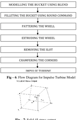
Fig – 6: Flow Diagram for Impulse Turbine Model
Fig – 7: Solid 45 stress output
The following figure shows the imported model of the impulse turbine model. PLOTTING STAGE = LINE
TOLERANCE USED = 0.0001
SOLVER TYPE = FRONTAL SOLVER
6.1
. Meshing Using Ansys
In preparing the model for analysis, Ansys subdivides the model into many small tetrahedral pieces called elements that share common points called nodes. A typical piece (element) is shown in the figure.
Type of mesh = global Element size = 0.5 Mode of mesh = volume Key points = all
MODELLING THE BUCKET USING BLEND
FILLETING THE BUCKET USING ROUND COMMAND
PATTERING THE WHELL
EXTRUDING THE WHEEL
REMOVING THE SLOT
CHAMFERING THE CORNERS
following figure shows the final results of structural analysis for different materials like austenitic alloy, titanium alloy, plastic reinforced carbon and 304 stainless steel.
Fig – 8: Meshing using ansys
VII. RESULT & DISCUSSION
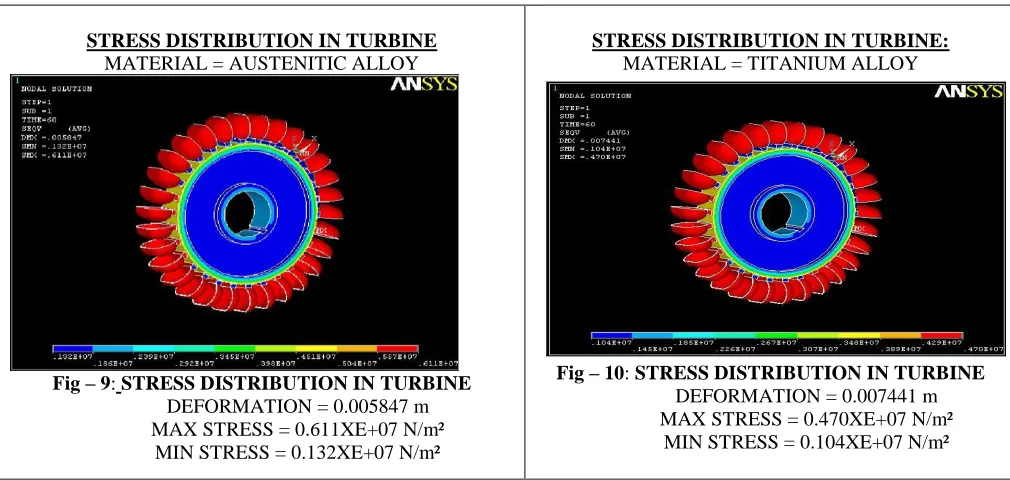
STRESS DISTRIBUTION IN TURBINE
MATERIAL = AUSTENITIC ALLOY
Fig – 9: STRESS DISTRIBUTION IN TURBINE
DEFORMATION = 0.005847 m MAX STRESS = 0.611XE+07 N/m²
MIN STRESS = 0.132XE+07 N/m²
STRESS DISTRIBUTION IN TURBINE:
MATERIAL = TITANIUM ALLOY
Fig – 10: STRESS DISTRIBUTION IN TURBINE
DEFORMATION = 0.007441 m MAX STRESS = 0.470XE+07 N/m²
The following figure shows the thermal distribution in the turbine for different blade materials like austentic alloy, titanium alloy, plastic reinforced carbon and 304 stainless steel.
7.1. Austenitic Alloy:
TOTAL HEAT FLOW RATE:
HEAT FLOW RATE = (hPKA) 0.5 x tan h (ml)
Where, h = heat transfer coefficient (442 W/m²-K) P = perimeter of bucket (m)
A = area of bucket (m²)
K = thermal conductivity of material used (W/m-K) M = mass transfer rate (kg/s)
L = length the bucket.
m = (hP/KA) m = (442x89.844/17.3x.0592)0.5 m = 196.61 kg/s
HEAT FLOW RATE = (hPKA) 0.5 x tan h (ml)
= (442x89.844x17.3x0.0592)0.5 x tan h (196.61x2.2) = 201.66 Watt
7.2 TITANIUM ALLOY:
TOTAL HEAT FLOW RATE:
Where m = (hP/KA) 0.5 = (442x89.844/7x.0592) 0.5 = 309.56 kg/s
HEAT FLOW RATE = (hPKA) 0.5 x tan h (ml)
= (442x89.844x7x0.0592) 0.5 x tan h (309.56x2.2) = 59.632 Watt 7.3 PLASTIC REINFORCED CARBON:
TOTAL HEAT FLOW RATE:
Where m = (hP/KA) 0.5 = (442x89.844/24.3x.0592) 0.5= 170.52 kg/s
HEAT FLOW RATE = (hPKA) 0.5 x tan h (ml)
= (442x89.844x24.3x0.0592) 0.5 x tan h (170.52x2.2)= 239.01 Watt 7.4 304 STAINLESS STEEL:
TOTAL HEAT FLOW RATE:
Where m = (hP/KA) 0.5 = (442x89.844/16.2x.0592) 0.5= 208.54 kg/s
HEAT FLOW RATE = (hPKA) 0.5 x tan h (ml)
= (442x89.844x16.2x0.0592) 0.5 x tan h (208.54x2.2)= 190.14 Watt. TABULATIONS:
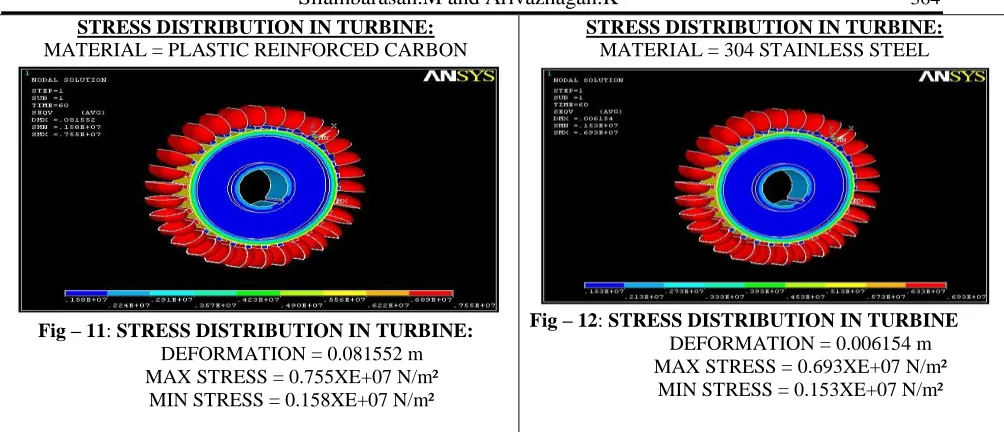
MATERIAL = PLASTIC REINFORCED CARBON
Fig – 11: STRESS DISTRIBUTION IN TURBINE:
DEFORMATION = 0.081552 m MAX STRESS = 0.755XE+07 N/m²
MIN STRESS = 0.158XE+07 N/m²
MATERIAL = 304 STAINLESS STEEL
Fig – 12: STRESS DISTRIBUTION IN TURBINE
DEFORMATION = 0.006154 m MAX STRESS = 0.693XE+07 N/m²
FATIGUE RESULT TABULATION:
THERMAL RESULT TABULATION
CONCLUSIONS
These show satisfactory order of results in approximating the nominal stresses in the blade due to the axial and tangential loading cases. Thus, having confirmed the range of stresses we would expect from ansys calculations, we can be confident in the finite element results.
From the results of the finite element analysis it is clear that a sizeable factor of safety is available with respect to this design stress, even when the correction factor is taken into account.
Generally, the dominant force in this stress analysis is the tangential force, but at the lower deformation, the most important force is in fact the axial load. All things being equal, one would generally expect the axial load on an impulse turbine to be small, since the impulse turbine at its design point does not experience an appreciable pressure drop across the rotor (in fact a slightly negative degree of reaction might not be unexpected).
But the max equivalent stress is induced in the titanium alloy blade material is less when compared to the other materials. But maximum stress is induced in the plastic reinforced carbon material. So that the life of the turbine blade may decreased.
When concentrating on the deformation graph comparison, the materials austenitic alloy and titanium alloy will produce the same deformation as compared to the 304 stainless steel. But the plastic reinforced carbon will produce the more deflection under tangential and axial load.
Material
(n/m²) (n/m²) (m)
Austenitic Alloy 0.611XE+07 0.132XE+07 0.005847
Titanium Alloy 0.470XE+07 0.104XE+07 0.007441
Plastic Reinforced Carbon 0.755XE+07 0.158XE+07 0.081552
304
Stainless Steel 0.693XE+07 0.153XE+07 0.006154
MATERIAL FOS
Austenitic Alloy 8.516
Titanium Alloy 4.79
Plastic Reinforced Carbon 1.657
304 Stainless Steel 3.506
Material Austenitic Alloy Titanium Alloy Plastic Reinforced
Carbon 304 Stainless Steel
Heat flow rate
As a consequence of the significant amount of time spent away from the design point, the result of negligible pressure drop across the rotor is no longer valid and an appreciable axial force is present. Finite element stress analysis results must also be evaluated, but the fact that stress analysis is so much more.
It may be noted that, considering the thermal analysis carried out on the different materials which shows the heat losses due to transfer must be less so that total heat is fully converted to mechanical energy; this may cause the increase in percentage of output power. In this analysis, Titanium alloy blade material provides the less heat losses compared to other materials. But in this case of plastic reinforced carbon material is considerably very high due to its high thermal conductivity. From the analysis the materials like austenitic alloy and titanium alloy produces the better structural and thermal behavior than the existing material.
REFERENCES
[1] Khaleeq, H.B. (2000). "Design analysis of 0.6m Impulse Turbine with fixed guide vanes for wave energy conversion". Proceedings of 4th Sir Bernard Cross land Symposium, 6-7 December 2000.
[2] SM YAHYA 1994, Turbines, Compressors And Fans ,Second Edition,Tata Mc Graw Hill,1983.SS [3] R C Sachdeva 1994 , Fundamentals of engineering heat and mass transfer , New Age India Co.,
[4] Ilaakker, A., Khaleeq, H.B., and Setoguchi, T., (2000a). "Performance comparison of 0.3m and 0.6m Impulse turbine with fixed guide vanes - Part I". Proceedings of the 4 'h European Wave Energy Conference, Aalborg, Denmark.
[5] RS Khurmi, JK Gupta, A Text Book Of Thermal Engg., S Chand And Co publications. 1994.