MEMBRANE BIO-REACTOR
Prashanth N11. INTRODUCION
Waste water contains about 0.5% solid impurity (includes dissolved, suspended and volatile impurities) by weight. The presence of these impurities is highly dangerous for daily consumption and drinking purposes. Therefore to remove these harmful impurities and bring water to standards as mentioned in IS: 10500 of the Indian standard. Also industrial effluents containing toxic chemicals are released into water bodies thereby increasing the need for advanced treatment.
1.1 What is a membrane?
A membrane is defined as a material that forms a thin wall capable of selectively resisting the transfer of different constituents of a fluid and thus effecting a separation, of the constituents. Thus, membranes should be produced with a material of reasonable mechanical strength with a high degree of selectivity. The optimal physical structure of the membrane material is based on a thin layer of material with a narrow range of pore size and a high surface porosity. This concept is extended to include the separation of dissolved solutes in liquid streams and the separation of gas mixtures for membrane filtration.
1.2 What is a bio-reactor?
Bioreactors are reactors that convert or produce materials using functions naturally endowed to living creatures. Reactors using immobilized enzymes, microorganisms, animal, or plant cells and those applying new methodologies such as genetic manipulation or cell fusion are typical bioreactors. Bioreactors differ from conventional reactors as living organisms present in the reactors
1Department of Civil Engineering Sathyabama University, Chennai, Tamil Nadu, India
DOI: http://dx.doi.org/10.21172/1.73.540 e‐ISSN:2278‐621X
operate under milder conditions of temperature and pressure. The ranges of operating conditions within bioreactors are usually determined by the biocatalyst (organism) and are usually small.
1.3 What is a membrane bio-reactor?
MBRs are suspended growth activated sludge treatment systems that rely upon membrane filtration for liquids/solid separation prior to discharge of the treated effluent, thereby replacing the solids separation function of the secondary clarifier.
1.4 Classification of membrane’s.
The typical membranes can be classified based on the following criteria’s,
The driving force used for the separation of impurities, such as pressure, temperature, concentration gradient, partial pressure, electrical potential etc.
The structure and chemical composition,
The mechanism of separation,
The construction geometry of the membrane.
1.5 MAIN DESIGNS AND CLASSIFICATION OF MBR
MBR applications for wastewater treatment can be classified into four groups, namely:
1. Extractive Membrane Reactors
2. Bubble-less Aeration Membrane Bioreactors
3. Recycle Membrane Reactors
4. Membrane Separation Reactors
The main designs for MBR plants are,
The membranes can be submerged directly in the bioreactor.
Submerged in multiple side tanks with a constant recirculation of water.
II METHODOLOGY
A typical water treatment under this process has to undergo a pre-screening or Pretreatment- involves primary clarification or screening with 0.5 – 3 mm screens to remove large particles and debris. The addition of coagulant may be needed to condition the filter cake and improve flux. This thereby reduces the load and pressure of the succeeding processes. After the pretreatment process the water sample is collected in sludge tanks.
pure water. This membrane with help of slight pressure removes pure water from the tank. This removal is a continuous process which supplements the bacterial action in the tank. On reaching complete purification, due to the absence of food the micro-organisms start to perish. These can be taken out separately and can be reactivated by anaerobic process and can be re-used without loss in efficiency.
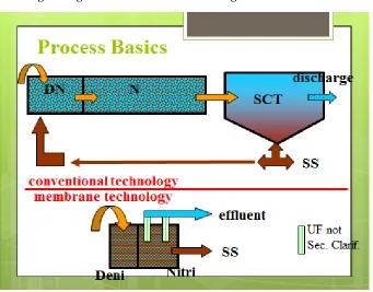
Fig 2.1 Figure shows the two main designs of an MBR Plant
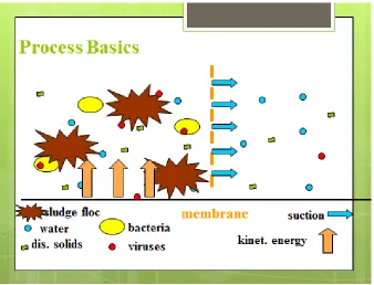
Fig 2.3 Diagrammatic explanation of the process of a membrane.
Fig 2.4 comparison between conventional, conventional with activated sludge and MBR techniques.
III. RESULTS AND DISCUSSIONS
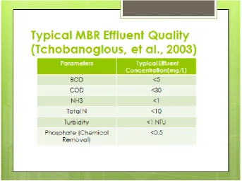
Fig 3.1 tabulation of the effluent quality of the treated wastewater by MBR technique. Most membrane filtration processes require quite a high Trans membrane pressure in order to produce an acceptable permeate flow rate. By contrast, the membrane bioreactor operates with a low differential, of about 0.5 bar. This can be provided by a vacuum pump, sucking on the permeate discharge line, through a receiver, or by the hydrostatic head of a deep bioreactor tank, or by a low level of pressurization of this tank. An MBR is capable of removing suspended solids to levels of below 5 ppm and BOD to below 10 ppm (and much better in some cases), which figures are comfortably below the current 20/30 requirements for marine and watercourse discharges. By careful choice of membranes a membrane bioreactor system can retain chlorine resistant pathogens such as Cryptosporidium and Giardia. The longer sludge retention times permit the reduction of molecules difficult to biodegrade, such as detergents. With proper system design nitrogen and phosphorus contents can also be significantly reduced.
Flux Rate – depends on waste water characteristics. Flux rate have impact on membrane life and cleaning frequency. Standard flux rate ranges between 50 and 200 L/m2h. Equalization basin is needed if the flux rate is inadequate. (Rate at which membrane takes in water).
Substrate and Solids Removal – the treatment by MBR process leads to a 100% removal of suspended solids. It is suited for high strength waste water with COD and BOD loads up to 13,000 mg/L and 6,500 mg/L respectively (Scott and Smith, 1996). COD removals ranging from 89 to 97% have been reported (Pankhania et al., 1999; Scott and Smith, 1996; Rosenburger et al., 2002; Xing et al., 2000; Xing et al., 2001). Further investigation revealed that the majority of COD removal occurred in the bioreactor with the membrane separation contributing 8 to 12% of the total removal (Xing et al., 2000; Xing et al., 2001).
3.2 Advantages of MBR technology
Secondary clarifiers and tertiary filtration processes are eliminated. Thereby reducing plant footprint. In certain instances, footprint can be further reduced because other process units such as digesters or UV disinfection can also be eliminated/minimized (dependent upon governing regulations).
No reliance upon achieving good sludge settle ability, hence quite amenable to remote operation.
Can be designed with long sludge age, hence low sludge production.
Produces a MF/UF quality effluent suitable for reuse applications or as a high quality feed water source for Reverse Osmosis treatment. Indicative output quality of MF/UF systems include SS < 1mg/L, turbidity <0.2 NTU and up to 4 log removal of virus (depending on the membrane nominal pore size). In addition, MF/UF provides a barrier to certain chlorine resistant pathogens such as Cryptosporidium and Giardia.
IV. CONCLUSION
1. Full-scale MBR provide a superior effluent quality compared to conventional methods. 2. The final effluent can meet the requirements of the Urban Wastewater Directive 91/271/EEC
even for P.E. >100,000 with disposal to sensitive recipients (TN <10 mg/l, TP < 1mg/l). 3. Final effluent conforms to the microbiological requirements for bathing waters (Directive
76/160/EEC), without the need for further disinfection with chlorine or ozone. 4. Enhance reuse options of secondary effluent.
However:
1. The stricter microbiological criteria for agricultural reuse are not met and further disinfection is required.
2. Main barrier to their wider full-scale adoption is the high operational cost and the lack of economies of scale.
V REFERENCES