Implementation Of Double Closed-Loop Control
System For Unmanned Ground Vehicles
Thin Thin Soe, Hla Myo Tun
Abstract: The research work focuses on issues of vehicle modeling incorporating wheel-terrain interaction and low-level control design taking into account uncertainties and input time delay. Addressing these issues is of significant importance in achieving persistent autonomy for outdoor UGVs, especially when navigating on unprepared terrains. The vehicle is driven in the skid-steering mode, which is popular for many off-road land vehicle platforms. In this research work, a comprehensive approach is proposed for modeling the dynamics of UGV. The approach considers the difference in speed between two outputs of the differential and the turning mechanism of the vehicle. It describes dynamics of all components in the vehicle driveline in an integrated manner with the vehicle motion. Given a pattern of the throttle position, left and right braking efforts as the inputs, the dynamic behavior of the wheels and other components of the UGV can be predicted. For controlling the vehicle at the low level, PID controllers are firstly used for all actuators. As many components of the vehicle exhibit nonlinearities and time delay, the large overshoots encountered in the outputs can lead to undesirable vehicle behaviors. To alleviate the problem, a novel control approach is proposed for suppression of overshoots resulting from PID control. As a result, the proposed approach can improve significantly system robustness and reduce substantially step response overshoot. Notably, the design is generic in that it can be applied for many dynamic processes. Knowledge of the interaction between the UGV and the terrain plays an important role in increasing its autonomy and securing the safety for off-road locomotion. The novel interaction model takes into account the relationship between normal stresses, shear stresses, and shear displacement of the terrain that is in contact with the wheels in deriving the three-dimensional reaction forces. Finally, all modeling and control algorithms are integrated into a unique simulator for emulating the vehicle mobility characteristics. In particular, the wheel’s slip and rolling resistance can also be derived to provide useful information for closed-loop control when the UGV is navigating in an unknown environment.
Index Terms: Double closed-loop control strategy, UGV, Autonomous Vehicle, MATLAB, Stability Analysis.
————————————————————
1
I
NTRODUCTIONAUTONOMOUS vehicle technology is rapidly developing, but the fundamental difference between human controlled (manned or tele-operated) and automatically guided vehicles remains is the ability of humans to diagnose and adapt to changing or unexpected operating conditions versus the relative rigidity of autonomous controllers. For this reason, most high-speed UGV research to date has focused on operations in relatively benign environments, namely paved roads, open tracks, and relatively smooth open fields or has been restricted to low-speeds. Many large scale off-road autonomous navigation projects such as the DARPA PerceptOR program, XUV DEMO III program, and extraplanetary rover research are largely focused on the perception and planning aspects; difficult terrain surfaces are either avoided or traversed at low speeds [1] [2]. High-speed autonomous vehicles have been demonstrated, notably by Volkswagen and BMW, but these demonstrations have been, as of 2011, limited to well-known, highly accurately modeled vehicles under tightly controlled circumstances. Probably the best known event involving high-speed operation on unknown terrain was the DARPA Grand Challenge (DGC) series. Both the 2004 and 2005 DGCs required vehicles to traverse an unknown cross-country course at high-speed. A review of the technical papers demonstrates that terrain information was used to plan paths around difficult surfaces and nonlinearities encountered in the surfaces were handled by feedback control. Advanced vehicle dynamics integration was largely neglected [3]. However, it should be noted that the courses for the DGC consisted primarily of well groomed, hard packed roads where the terrain surface was largely uniform and unchallenging [4]. However, situations did occur where vehicle dynamics became significant [5]. In testing, the Red Team rolled their vehicle, Sandstorm, while operating at high-speed. Due to an error in the planned path, the vehicle attempted to execute a hard turn beyond its dynamic capabilities. The team’s recommended solution to this occurrence is implementation of a better model of the robot safety margins in
258
whereas that same speed would be unfeasibly high (and extraordinarily dangerous) for a loaded mining haul truck. High-speed operation can qualitatively be connoted in operational terms as movement at speeds similar to that at which an efficient human operator would command in the current operating environment to rapidly complete the desired task. A more rigorous definition for purposes of this work would define low-speed as the maneuvering region in which quasi-static motion constraints can be considered valid. The corollary to this would define high-speed as the regime in which dynamic effects must be considered in order to accurately define motion constraints, often in a non-linear fashion. It is also important to note that the line between high and low-speed operation is not static, even for a single vehicle. Changes in payload, vehicle configuration, or environmental conditions can result in rapid shifts in the regimes. In extreme cases, these shifts may even effectively eliminate the low-speed region. One of the difficulties to the expansion of vehicle dynamics into autonomy is the difficulty of accurately modeling the vehicle itself. Despite the fact that a considerable amount of literature and expertise including a number of commercial modeling packages are available, autonomy integrators often do not have easy access to the data required to develop an accurate model as the vehicles are often converted from existing platforms without access to the Original Equipment Manufacturer (OEM) design specifications. The process to develop such a model can be highly labor intensive and involve extensive testing and specialized equipment that make it economically undesirable to conduct. Furthermore, a fixed parameter model only represents the vehicle in a single configuration and may not accurately represent the actual load state and operational conditions encountered. In light of these difficulties, most current UGV applications rely on simple linear kinematic models [8] [9]. Kinematic models differ from true dynamic models in that they are time-invariant and do not take into account the time delays that occur between state transitions in real systems and the coupling that results. While vehicle handling can be represented as a linear system, this limits the effective operating range and accuracy of the model to the low-speed operating regime since real vehicles behave in a highly non-linear manner as the edge of the operating high-speed range is approached [10]. It should be noted that for many applications the vehicles do not operate outside of the low speed range in which the linear kinematic models are applicable. If operation under these conditions can be guaranteed, then use of simplified models is easily justifiable as more complex dynamic models are unlikely to significantly improve prediction performance in the low-speed linear kinematic range. However, many realistic commercial applications will require expansion into the high-speed regime. The motivation behind the integration of more advanced dynamic models into autonomous systems is to expand the effective safe operational envelope of UGVs. Even if the vehicle may never be intended to leave the low-speed region, uncertainties in the operating environments of most real applications mean that operation outside of the intended range may occur. As has been noted, it is also possible for UGVs to become dynamically unstable even in environments with low uncertainties when the limits of the vehicle platform are exceeded. If these limits are not well known, prudence demands that the limits be underestimated, reducing vehicle performance. It is therefore important to be able to predict the stable operating range of the vehicle in real-time so that the
vehicle can be operated efficiently and safely at speeds high enough to be useful in real applications.
2
P
ROPOSEDA
PPROACH2.1 Driveline Modeling
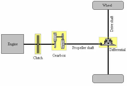
The driveline is the power transmission system of a vehicle. It transfers the power from the engine to the wheels. Many cars and trucks have the same basic configuration of driveline, which consist of engine, clutch or torque converter, gearbox, propeller shaft, differential, drive shaft, and wheels, as shown typically in Figure.1.
Figure .1 Driveline Configurations
Figure.2 Driveline of the Vehicle
The differential, while transferring equal torque to each drive wheel, enables the left and right wheels to run at different speeds in turning to avoid slipping. However, in an Ackermann-steering configuration found in most cars and trucks, the differential has a passive role in turning because the turning rate is mainly determined by the steering wheel angle. Therefore, the mechanism for that purpose is normally not considered in the modeling of a vehicle differential and it is described as the same way as a gearbox. Ignoring the difference in rotational speeds, all drive wheels can be combined and modeled as one wheel. Newton's second law, both in the form of rotational and linear motions, is used to describe the wheel dynamics [13]. The torque supplied from the vehicle differential through the drive shaft, after overcoming internal and external friction torques, provides the wheel acceleration. The external friction torque provides the force required for the vehicle to accelerate and overcome rolling resistance, air drag, and gravitational force. Figure .2 shows the driveline configuration used for the UGV under investigation in this thesis. Instead of a normal clutch, this driveline uses a Continuous Variable Transmission (CVT). It is a V-belt CVT which can change driver or driven clutch radius depending on acceleration or load. The mechanics of this component are complicated and will not be analyzed in details in this thesis. Instead, it is modeled by a variable gear ratio which is simplified as a linear function of engine speed and load, based on experiment.
2.2 Vehicle control
In the first stage of the development, the original vehicle driveline is equipped with actuators and sensors which require suitable controllers. At the low level, the throttle position and brake efforts need be controlled. The motion controllers to be developed have to be able to track the vehicle velocity and turning rate references, as shown in Figure.3.
Figure.3 UGV Control Requirements
3
I
MPLEMENTATIONThere are three contributions in the vehicle driveline developments. First is the model of CVT. Although simplified and linearised from experiment data, it is able to describe the complex relationship between the input and output.
Figure.4 SIMULINK Model for UGV
Second is the model of the vehicle differential during turning. In driveline modeling for cars or trucks, the turning mechanics are usually ignored. In contrast, in this model, the difference in rotational speeds between the differential outputs are analyzed and expressed explicitly in terms of a first order transfer function of the difference in loads between the outputs. An overall time constant for the differential derived to relate to the weight of the vehicle, wheels, with viscous friction coefficients of the wheels and the differential. The most important contribution is the incorporation of terrain interaction in the driveline model. Most driveline models ignore this interaction or assume that it obeys the Coulomb friction law which is not exactly valid for UGV navigation over deformable terrain. Meanwhile, the complex processes involved in the wheel-terrain interaction are integrated into the vehicle model, resulting in more accurate prediction. The SIMULINK model for UGV is shown in Figure. 4. The simulator for the whole vehicle, incorporating the driveline model, terrain interaction model, and the basic motion controllers, is helpful for further developments on the UGV mobility characteristics. Alternatively, it can be used to predict the response of the vehicle on a certain terrain with a pattern of inputs.
4
S
IMULATIONR
ESULTS260
Figure. 5 Position, Velocity and Acceleration Response for
Front Center Vehicle
This is very important because the performance of a skid steering vehicle in turning depends on the turning moment resistance which is mainly derived from the reaction forces acting on the wheels in the lateral direction.
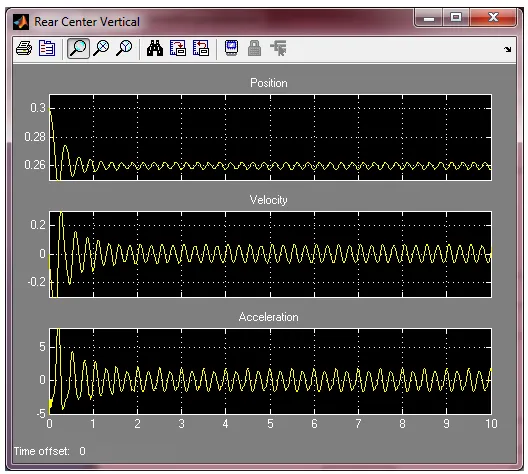
Figure. 6 Position, Velocity and Acceleration Response for
Front Left Wheel Vehicle
The development is applied to all wheels of the UGV to obtain the reaction forces from the terrain acting on the wheels, the turning moment and turning movement resistance.
Figure. 7 Position, Velocity and Acceleration Response for
Front Right Wheel Vehicle
Combined with the vehicle kinetics, all characteristics related to the UGV-terrain interaction such as the vehicle velocity, turning rate, slip ratios, traction, drawbar pull, and resistances have been comprehensively formulated provided that the terrain parameters are known. A significant contribution in this work is that it improves the accuracy of the approximation method, applied for the normal and shear stresses, to speed up the computation process for the terrain interaction analysis.
Figure. 8 Position, Velocity and Acceleration Response for
Figure. 9 Position, Velocity and Acceleration Response for Rear Right Wheel Vehicle
Thus, the analysis is able to be performed with a high computational efficiency while it is also accurate enough as compared with the relevant method reported in the literature. Using this approach, a new terrain interaction model is developed for online prediction of vehicle behavior.
Figure. 10 Position, Velocity and Acceleration Response for
Rear Left Wheel Vehicle
According to the SIMULINK model design for UGV system, the position, velocity and acceleration responses for Front Center Vehicle, Rear Center Vehicle, Front Right Wheel Vehicle, Front Left Wheel Vehicle, Rear Right Wheel Vehicle, and Rear Left Wheel Vehicle are shown from Figure. 5 to 10.
5
C
ONCLUSIONThis paper has presented the modeling and control of a skid-steering unmanned ground vehicle (UGV). In particular, the vehicle driveline has been analyzed and a model was developed to predict the behaviors of its components. In addition, the complex processes involved in the interaction between the wheels and terrain have been analyzed and an interaction modeling procedure was proposed. Combined with the driveline model and realized by a fast algorithm in a UGV simulator, every significant dynamic process involved in the vehicle mobility, from the driveline to the terrain interaction, Furthermore, a new control approach was proposed to eliminate overshoot for stability controlled-loops with input time-delay, and to achieve robustness against nonlinearities and uncertainties. Applied for controlling the vehicle throttle, brakes, velocity, and turning rate, the proposed approach has given better vehicle dynamic performance than can be achieved using stability control.
A
CKNOWLEDGMENTI would wish to acknowledge the many colleagues at Mandalay Technological University who have contributed to the development of this paper.
R
EFERENCES[1]. Artstein, Z. (1982). "Linear systems with delayed control: A reduction." IEEE Transaction on Automatic Control, 27(4), 869 - 879.
[2]. Aström, K. J., and Hagglund, T. (1995). PID Controllers: Theory, Design, and Tuning, Instrument Society of America.
[3]. Aström, K. J., and Hagglund, T. (2004). "Revisiting the Ziegler-Nichols step response method for PID control." Journal of process control, 14(6), 635-650.
[4]. Balluchi, A., Benvenuti, L., Lemma, C., Murrieri, P., and Sangiovanni Vincentelli, A. L. (2005). "Hybrid models of an automotive driveline." Internal Technical Report, PARADES, Rome.
[5]. Bekker, M. G. (1956). Theory of Land Locomotion, University of Michigan Press, Ann Arbor.
[6]. Bekker, M. G. (1969). Introduction to Terrain-Vehicle System, University of Michigan Press, Ann Arbor.
[7]. Besharati Rad, A., Lo, W. L., and Tsang, K. M. (1997). "Self-tuning PID controller using Newton-Raphson search method." IEEE Transactions on Industrial Electronics,
44(5), 717-725.
[8]. Camacho, O., Rojas, R., and García, W. (1999). "Variable structure control applied to chemical processes with inverse response." ISA Transaction, 38(1), 55-72.
262
[10]. Cho, J., Sung, S., and Lee, I. (2002). "Cascade control strategy for external carbon dosage in predenitrifying process." Water Science and Technology, 45(4-5), 53-60. [11]. Cominos, P., and Munro, N. (2002). "PID controllers:
Recent tuning methods and design to specification." Control Theory and Applications, IEE Proceedings, 149, 46-53.