© 2017 IJSRST | Volume 3 | Issue 3 | Print ISSN: 2395-6011 | Online ISSN: 2395-602X Themed Section: Engineering and Technology
A Review on Split Cycle S. I. Engine & Axial S.I. Engine (Duke Engine)
Compared with Conventional S. I. Engine
Ch. Mani Kumar, P. Rajendra Babu, R Narendra Kumar, Y. Raghu Ram
Assistant Professor, Sasi Institute of Technology & Engineering, Tadepalligudem, Andhra Pradesh, India
ABSTRACT
Internal combustion engines play an important role in percent scenario, there study is also very important in research for many automobile industries and also environmental concerns. Automobiles changes day by day based on the customer requirements (Low fuel consumption, Low vibrations, and safety). IC engines are used not only in automobile industries but are also used in sea as well as air for transportation, as a prime mover for electric generators and in industrial applications. There efficiencies and their environmental impacts are very important for both the human and environment. A new IC engine developed by the Scuderi group called ‘Scuderi Split Cycle Engine’ and also a new engine technology developed by New Zealand Duke Engines is called axial S.I. engine (Duke Engine). The engine working, performances are described in this review paper. These engines are more efficient than the conventional engines and also have less emissions. These engines have high volumetric, thermal and relative efficiencies. Maas of fuel consumption and vibrations are less.
Keywords: Conventional Engine, Split Cycle Engine, Axial Engine.
I.
INTRODUCTION
Most of the automobiles use conventional engines. The conventional engines are classified in to in line engine, rotary engines and v type engines mainly. In conventional engines, the four strokes and four processes occurs in single cylinder. In scuderi split cycle engine the four strokes and four processes occur in paired cylinders. The first cylinder is called as compression cylinder, in this the suction & compression process occurs and the second cylinder is called as expansion cylinder, in this the combustion, expansion & exhaust processes occurs. Both the cylinders are connected by a cross way passage. In some conventional engines, the number of cylinders are located in one by one in straight path (In line engines) and crank and piston axis perpendicular to each other. In these engines cylinders are not rotated. The new technology engine introduces is called axial engine. These axial engines have cylinder and crank both are rotated. All the cylinders are located in circular path.
II.
METHODS AND MATERIAL
Anshul Jangalwa et.all (2013) They concluded split cycle engines were more
efficient than the conventional engines. Scuderi split cycle engine had high power out puts, efficiencies and low emissions [1].
Prof. Dattu Balu Ghane (2015)
He concluded the Scuderi Split Cycle Engine solved both the breathing (volumetric efficiency) and thermal efficiency problems by unique valve design and Firing After Top Dead Center (ATDC) . Split cycle engine is more efficient than the conventional IC engines [2].
Sudeer Gowd Patil et.all. (2012)
They concluded the peak pressure, thermal efficiency and power output of the Scuderi engine was 11 bar at 300 rpm, 5% and 20% more than the conventional engines [3].
Prince Bora et.all. (2015)
Guangyu Dong et.all. (2015)
He studied that expansion ratio is increased to 26 since a 2.8% total efficiency improvement still can achieved from over expansion [5]
Siddhartha Joshi (OCT 10/2016)
In this paper he was said that Overall economy of Duke Engine is less as compared with modern conventional engines he concerns in terms part or full load fuel performance, design aspects and manufacturing aspects. Frictional losses that faced in internal combustion engines are reduced due to reduction in parts. Diesel oxidation catalyst will be very effective in this engine because of generation of high exhaust temperature [6].
Ardiyansyah Syahrom et.all (2006)
In this paper wobble-plate compressors are mainly used in automotive, air-conditioning systems, which require low pressures that can be achieved using single-stage compression. The advantages and applications of wobble plate compressors are further enhanced with the introduction of the symmetrical wobble-plate configuration of duke engine [7].
New Zealand company Duke Engines started in 1993 has created several different engines and installed one in a car in 1999. The engine runs a 5-cylinder, 3 liters, 4 stroke internal combustion engine platform with its unique axial arrangement, which is in its third generation. Current prototypes of Duke's engines claim to match characteristics of conventional internal combustion engines but with less number of parts and at a 30% less weight. This goes in the direction of developing a more efficient engine. During development, the Duke has been tested at MAHLE Powertrain in the United Kingdom and in the United States; test results are available with it also having multi-fuel capabilities [9].
1. Parts of the Split Cycle Engine
1. Compression Cylinder 2. Expansion Cylinder 3. Compression Piston 4. Expansion Piston
5. Crossover Passage and Crossover Valves 6. Intake/Exhaust Valve
7. Crank and Crankshaft
8. Fuel Injector 9. Spark Plug
Figure 1. Components of split cycle engine[1]
The efficiency of an internal combustion engine is increased only in if the gas is expanded quick in expansion piston in expansion process. In Split Cycle Engine, the design of compression cylinder is different from that of the expansion cylinder. The displacement volume of compression cylinder is less than that of the displacement volume of the power cylinder (DC> DP). Due to this arrangement, more work is obtained in power stroke and less work has to be given in compression stroke which is not possible in conventional IC engine.
Compression and Expansion Cylinder
In compression cylinder suction and compression process occurs. In expansion cylinder combustion, expansion and exhaust process occurs. The compression cylinder consists of a piston, inlet valve and the crossover compression valve whereas a power cylinder or expansion cylinder consists of a piston, exhaust valve, crossover expansion valve.
Crossover Passage
the cylinders. These valves not required any mechanism to operate.
Intake/Exhaust Valves
These valves are operated by cam, trough Intake valve the atmospheric air enters in to the compression cylinder and trough exhaust valve the exhaust gases leaves from the power cylinder.
Fuel Injector
This is used to inject the fuel where it mixes with air and forms a good mixture of air and fuel which is very important for the proper combustion of the charge.
Crank shaft
The pistons of both the compression and power cylinder are connected to the Crank shaft. Reciprocation motion of the piston is converted into the rotary motion by the crank shaft.
Spark Plug
It gives the spark necessary to ignite the fuel and start the process of combustion. The battery or magneto ignition systems are gives power supply to the spark plug.
Compression & Expansion Pistons
Compression piston located in compression cylinder and expansion piston is located in expansion cylinder. Both the pistons are connected to the crank and reciprocate in cylinders. In between the piston and crank connecting rod is connected. The figure 2&3 shows working of four stroke conventional and split cycle engines.
Figure 2. Conventional four stroke engine working
Figure 3. Four Stroke Split Cycle engine working
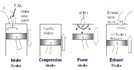
2. Working of Split Engine
The working of the engine is explained in four strokes: 1. Suction Stroke
2. Compression Stroke 3. Expansion Stroke 4. Exhaust Stroke
Suction Stroke
In suction stroke the piston moves from TDC to BDC so that the vacuum is created. Which results the intake air is drawn into the compression cylinder through an intake valve and it is located in the cylinder head. According to the valve timing diagram the
inlet valve opens and closes in suction stroke and these valves are operated by cam shaft.
Compression Stroke
In compression stroke the piston moves from BDC to TDC and pressurizes the air. Due to the high pressures of air the XovrC opens, drives the air to crossover passage. Fuel injector injects fuel into the pressurized air. Due to high pressures of charge the XovrE valve opens, which occurs shortly before starting of combustion. The cross over valves opens and closes depends up on the pressure differences between cylinders and cross over passage.
Figure 5. Compression[1]
Expansion Stroke
When XovrE valve opens, the pressure in crossover passage is substantially higher than the pressure in expansion cylinder. This high-pressure differences causes the charge entering into the expansion cylinder at high momentum. Before beginning of expansion stroke the spark is initiated. During combustion, the peak pressures are attained which crates trust force on expansion cylinder piston.
Figure 6. Expansion[1]
Exhaust Stroke
During the exhaust stroke, the exhaust gases are pumped out by the piston into the atmosphere trough exhaust valve.
III.
RESULTS AND DISCUSSION
Important Key Points
After Top Dead Centre Firing (ATDC Firing)
Conventional engines the firing (spark is initiated) is starts before top dead center in the compression process.
Reason for After Top Dead Centre Firing
In case if the firing starts BTDC in the split cycle engine the following problems occurs
Power loss in the power cylinder
The combustion starts in the cross over passage and the exhaust gases entering in to the compression cylinder. This happens loss of compression stroke (Because of the pressure differences between the two cylinders and cross over passage).
The power piston moves against to the exhaust gases i.e the piston moves towards upwards and exhaust pressure acting towards downwards on piston surface in start of expansion stroke.
Air Standard Otto Cycle
Fig.8. Theoretical Valve time diagram of conventional engine
The conventional engines work on Otto cycle. In the conventional engine, the four strokes occur in single cylinder (Bore, Stroke Length Swept volume and clearance volume ware fixed). In conventional engines inlet valve opens (IVO) BTDC in expansion stroke and inlet valve close (IVC) ABDC in compression stroke. When the inlet valve open BTDC some of the charge is mix with exhaust gas and escapes with exhaust gas, due this engine has power loss. When the inlet valve is closed ABDC some of the charge is escaped through inlet valve because of delay of inlet valve closing. To solve above problems in the split cycle engine. These cycle is works on miller cycle. The two important points are observed regarding split cycle engine.
The split cycle has larger expansion ratio than the compression ratio but the conventional engine which has the same compression and expansion ratio The volume of the expansion cylinder much greater
than the volume of compression cylinder. In conventional engine, the volume of expansion and compression should be same. Based on these two-points air standard Otto cycle is considered as split cycle or miller cycle
Miller Cycle
Miller cycle is a thermodynamic cycle used in internal combustion engines. This cycle is called as over expanded cycle. This cycle was patented by Ralph Miller.A Miller-cycle engine is similar to an Otto-cycle
engine. The Miller-cycle uses pistons, valves, a spark plug, etc., just like an Otto-cycle engine does.
The power output, efficiency of the internal combustion engine is depending up on the valve closing and opening time and work done on piston in expansion stroke. The miller cycle (over-expanded cycle) is implemented with either early (EIVC) or late (LIVC) intake valve closing. The primary effect of EIVC and LIVC is a reduction in temperature at the end of the compression stroke and increase effeminacy. If the inlet valve of the conventional engine closes late during the compression stroke the intake charge in cylinder (previous stroke) is pushed back by the piston into trough intake valve. Then the compression process occurs 80 to 90 percentage.
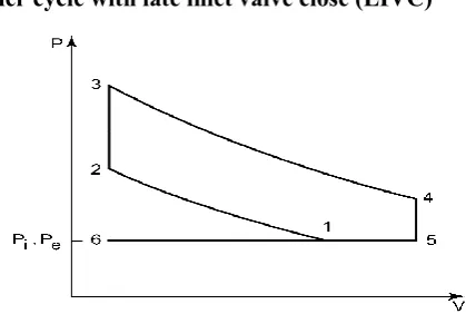
Miller cycle with late inlet valve close (LIVC)
Figure 9. Miller cycle with late inlet valve close (LIVC) [1]
The PV diagram shows the miller cycle with late inlet valve closing from the 6-5-1-1-5.
Operation 1-2: The compression cylinder piston pressurizes the air and XovrC opening, due to pressure differences between compression cylinder and cross over and by the piston the total air entering into the crossover passage. The XovrC valve opens at the end of the compression stroke. Fuel injector injects fuel into the pressurized air at the exit end of the crossover passage in correspondence with the XovrE valve opening, which occurs shortly this time the pressure in the crossover passage is more than that in the expansion cylinder.
Operation 2-3: The charge enters in to the expansion cylinder shortly after expansion piston reaches its top dead centre (TDC), The total charge completely enters before TDC in expansion cylinder. When the piston reaches the top dead centre, while the XovrE valve is still opens, at that time spark is initiated by the spark plug into the cylinder. The the combustion is started almost after TDC.
Operation 3-4: The XovrE valve is closed after combustion. The thrust force acting on the surface of the piston be the combustible mixture so that the piston move from TDC to BDC in expansion process.
Operation 4-5: In this process the exhaust gases expelled by the piston trough exhaust valve. i.e. During this process the exhaust valve opens and the gases are released from the power cylinder when piston moves from its BDC to TDC.
Miller Cycle with early inlet valve close(EIVC)
Figure 10. Miller cycle with early inlet valve close (LIVC) [1]
The PV diagram shows Miller cycle with early Inlet valve closing. the same effect in the late inlet valve
closing can be achieved in the Miller cycle by early inlet valve closing. During the intake stroke the pressure remains constant that is consider form the point 6 to 1. At a point 1 the intake valve closes before bottom dead centre BBDC. Further the pressure is decreases from point 1 to 7. The compression stroke starts from point 7, then the pressure increases from point 7 to 2. The path 1to 7 and oath 7 to 1 should be cancelled. The effective compression starts from point 1 to 2. The obtained result is same as to the late intake valve closing results. The work done should be same as to the to compress one kg of air with late inlet valve close and early inlet valve close. the effective compression ratio. The figures 11& 12 shows the P-V compression and power curves.
Figure 11. P-V Curve for compression Cylinder [2]
Compression Curve
Figure 12. P-V Curve for power Cylinder[2]
Power or Expansion Curve
Expansion process is a positive work i.e. the gas does work on piston. When the expansion cylinder piston reaches BTDC XovrE valve opens then the charge is entering in to the expansion cylinder. When the piston reaches ATDC the spark is initiated by the spark plug and combustion starts. The combustible gases crates thrust force on piston surface, the piston moves from TDC to BDC. The exhaust gases will leave the expansion cylinder trough exhaust valve.
P-V curves for split cycle engine
Figure 13. P-V curves of conventional and scuderi split cycle engine [3]
Figure 14. Power and Torques of conventional and split cycle engine[3]
The fig shows variations of pressures with respect to cylinder volumes. The area under the curves represents the work done. The amount of work done acting on the power cylinder piston much greater than the conventional piston in expansion stroke.
The fig shows power and torque curves of conventional and scuderi split cycle engine. The power and torque varies between 1500rpm to 3000rpm. In conventional engine when the speed of the engine reaches 3000 rpm torque drops gradually, volumetric efficiency decreases and frictional losses increases. Torque curves of scuderi split cycle engine is shown in fig. The torque curve of the split cycle engine is high because of at low speed the amount of time is available for effective combustion. When the engine speed increases further the torque reduced. The torque, power and efficiencies of split cycle is greater than the conventional engine.
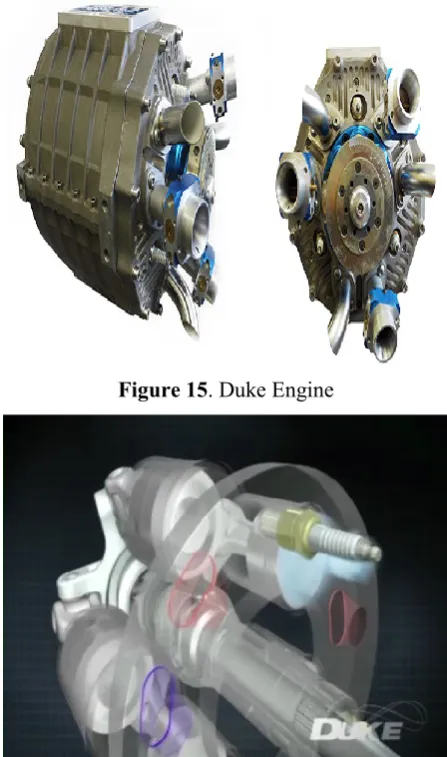
Duke engine
Duke engines are advanced engines with a unique high speed, valve less high speed 5 cylinders, 3 injectors axial internal combustion engine.
Components of duke engine
Cylinder Piston
Connecting rod
Figure 15. Duke Engine
Figure 16. Suction pocess or Suction stroke
Figure 17. Compression Stroke
Figure 18. Combustion
Figure 19. Expansionstroke
Figure 20. Exhaust stroke
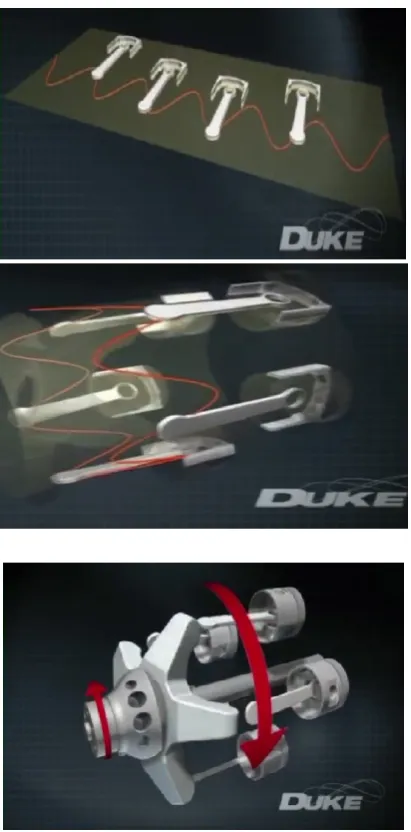
Figure 22. duke engine piston, connecting rod and crankshaft arrangement Sinusoidal motion.
Duke engine is four stroke internal combustion engine which has five cylinders. The engine capacity is three litters. The duke engine cylinders arranged from linear arrangement into circular orientation (sinusoidal wave). The engine works on the principle of wobble plate. The wobble does not rotate round and it is connected to Z shaped crank. The wobble plate translates the motion from the piston to crank. The pistons are mounted in mono block which rotates around the shaft. These pistons drive a star shaped component is called reciprocator. The reciprocator allows all parts to move in sinusoidal motion. A stationary cylinder head mounted up on the mono-block (Cylinder block) with the help of bearings. The cylinder head consists of spark plugs and specially designed ports. The air and exhaust gases entering and leaving trough this ports. In suction stroke
the charge enters in to cylinder trough inlet port and compressed in the cylinder further exposed to the spark plug for ignition of power stroke. Due to power stroke the piston moves towards downwards so that the wobble plate rotates accordingly with cylinder head movements causing the piston reaches the exhaust port. There the exhaust gases leave the cylinder through exhaust port.
Advantages (Duke Engine)
Duke engine is high power density, small size, and low weight. This engine suitable for a motorcycle. Reducing the torque reactions, because of The
counter-rotating cylinder and crankshaft tend to cancel out gyroscopic reactions.
Duke engine fires three times per revolution of the output shaft—the same as a conventional six-cylinder engine.
Eliminate Vibrations
Limitations (Duke Engine)
Design of the ports operated mechanism is difficult
Advantages (Split cycle Engine)
Effective, clean and rapid combustion occurs. This engine having higher compression ratios,
because of individual compression and power cylinders.
The emissions are reduced (CO2 50% and NOx 80%) compared to conventional engines
Increase fuel efficiency up 50%. Increase power and torques
Limitations (Split Cycle Engine)
Cold air nerves enters into the power cylinder. Due to the peak temperatures viscosity of the
lubrication oil decreases.
Possible to occurs knocking in the engine.
IV.
CONCLUSION
problems in conventional engines. The axial engine (Duke Engine) have very less vibrations as compared to the conventional engines. Mechanical balance of the duke engine is perfect without adding any balance shafts. The fuel economy is low compared to conventional engines at part and full load conditions. From the design aspects, manufacturing aspects duke engine is best compared to conventional engines. The duke engine achieve power reduce cylinder areas, eliminate valve and valve operating mechanism.
V.
REFERENCES
[1]. Anshul Jangalwa "SCUDERI SPLIT CYCLE ENGINE: A REVIEW" International Journal of mechanical engineering and Robotics research ISSN 2278 – 0149 www
[2]. Prof. Dattu Balu Ghane "SCUDERI SPLIT
CYCLE ENGINE: REVOLUTIONARY
TECHNOLOGY & EVOLUTIONARY DESIGN REVIEW" International Journal of Innovation in
Engineering, Research and Technology
IJIERTICITDCEME’15 Conference Proceedings ISSN No - 2394-3696
[3]. Sudeer Gowd Patil1, Martin A.J.2, Ananthesha3- Study on Performance Characteristics of Scuderi Split Cycle Engine. SAS TECH (2012), Volume 11, Issue 1.
[4]. Prince Bora1, Neeraj Joshi2, Priyanka Hire3- The scuderi revolution: a review, 11 International Journals of Advanced Technology in Engineering and Science (2015),1348-7550
[5]. Guangyu Dong*, Robert.E. Morgan, Morgan.R. Heikal- Thermodynamic analysis and system design of a novel split cycle engine concept. [6]. Sidharath Joshi "Duke Engine: An Overview of
Present State of Art and Future Potential" International Journal of Scientific Engineering and Research (IJSER), ISSN (Online): 2347-3878, Impact Factor (2015): 3.791
[7]. Ardiyansyah Syahrom, Md. Nor Musa, Zair Asrar Ahmad, Ainullatf Abdul Latif "New Symmetrical Multi-Stage Wobble-Plate Compressor" International Compressor Engineering Conference at Purdue, July 17-20, 2006
[8]. Ahmad, Z.A., Abdul-Latif, A., Syahrom, A., and Musa, M. N., 2006, Effect of Side Force on the Structural Integrity of the New Symmetrical
Multi-Stages Wobble-plate Compressor, Regional Conference on Computational Mechanics & Numerical Analysis.
[9]. http://www.dukeengines.com/technolog y/ [10].
www.mecholic.com/2016/10/scuderi-split-cycle-engine-advantagesapplications.html
[11]. http://courses.washington.edu/me341/oct22v2.htm [12]. www.scuderiengine.org
[13]. http://www.swri.or [14]. http://www.wikipedia.org
[15]. Patent No. US 2005/0268609 A1, Date December 8, 2005.
[16]. Rajput R K (2007), Internal Combustion Engines, Laxmi Publications, New Delhi.
![Figure 1 . Components of split cycle engine[1]](https://thumb-us.123doks.com/thumbv2/123dok_us/9091348.1443946/2.595.309.509.81.259/figure-components-split-cycle-engine.webp)
![Figure 6. Expansion[1]](https://thumb-us.123doks.com/thumbv2/123dok_us/9091348.1443946/4.595.76.256.259.411/figure-expansion.webp)
![Figure 11. P-V Curve for compression Cylinder [2]](https://thumb-us.123doks.com/thumbv2/123dok_us/9091348.1443946/6.595.51.239.513.663/figure-p-v-curve-compression-cylinder.webp)
![Figure 12. P-V Curve for power Cylinder[2]](https://thumb-us.123doks.com/thumbv2/123dok_us/9091348.1443946/7.595.70.266.438.605/figure-p-v-curve-for-power-cylinder.webp)