IJSRR, 8(1) Jan. –March, 2019 Page 710
Research article
Available online www.ijsrr.org
ISSN: 2279–0543
International Journal of Scientific Research and Reviews
Implementation of Testing Methods for VLSI Circuits
A .Ooha
1and V. Leela Rani
21
M.Tech. Student, Department of Electronics and Communication Engineering, G.V.P. College of
Engineering (A), Visakhapatnam, AP-India, Email:
[email protected]
.
2
Associate professor, Department of Electronics and Communication Engineering, G.V.P college of
Engineering (A), Visakhapatnam, AP-India, Email: [email protected]
ABSTRACT
:
An ASIC chip designed may not meet the functionality requirements. There may be lot of
conditions which may cause damage to the designed circuit and effect its functionality. Those conditions
include processing faults (such as missing contact windows, oxide breakdown), material defects (such as
cracks, crystal imperfections), packaging failures etc. These problems may cause faults in the digital
logic circuits and effects circuit functionality. Therefore, the circuit must be tested in order to know
whether it is working properly or not.
Several testing methods and algorithms have been proposed such as D-algorithm, PODEM
algorithm, Built-in-self-test etc in literature. In this paper, Built-in-logic-block-observer (BILBO)
method of testing is implemented. A test pattern compaction method, STAR-EDT is combined with
BILBO to derive minimum number of test data for detecting all faults that are injected into the circuit.
The combined method called BILBO with STAR-EDT methodology is proposed. Existing and proposed
methods are implemented and applied to various test circuits. After that, a Scheduling method is applied
to BILBO with STAR-EDT method for all test circuits at a time. The proposed method requires less
number of test patterns than the number of patterns required in existing BILBO methodology.
Scheduling concept applied to proposed method results in reduced timing requirements for test
procedures.
KEYWORDS:
BILBO, STAR-EDT, Scheduling, Test data, Faults.
*
Corresponding author
Ms. A. Ooha
M.Tech. student,
G.V.P. College of Engineering (A)
Visakhapatnam, AP, India.
IJSRR, 8(1) Jan. –March, 2019 Page 711
INTRODUCTION:
An ASIC chip designed may not meet the functionality requirements. Several testing methods and algorithms have been proposed such as D-algorithm, PODEM algorithm, Built-in-self-test etc to test the designs in order to define whether it is faulty or fault-free. The D-algorithm and PODEM (Path-Oriented-Decision-Making) algorithm are external methods of test data application. Whereas, BIST (Built-In-Self-Test) architecture is designed on-chip and the entire testing process is done on chip. BIST is categorized into several types namely Logic BIST (LBIST), Memory BIST (MBIST), Scan-based BIST, Programmable BIST, BILBO etc3,4,5,8. In this paper, BILBO (Built-In-Logic-Block-Observer) method of testing is considered. BILBO needs more number of patterns to detect faults. A test data compression methodology STAR-EDT is used which derives minimum number of test patterns to detect more number of faults1,6. Testing multiple test circuits requires more time. Scheduling methodology is applied to test reduce the time consumption and hence, test circuits can be tested in a parallel way.2
BILBO METHODOLOGY:
BILBO (Built-In-Logic-Block-Observer) is one of the methodologies of BIST. It uses a register that operates in different modes based on its control inputs. The structure of BILBO register consists of flip-flops and a combinational logic comprising of XOR, NAND and NOR gates between every two flip-flops. Two control inputs are present in order to decide the mode of operation. The structure of BILBO register is shown in Figure 1.
Figure 1: Architecture of BILBO register B1 B2 QN-1 QN ~Q1 Q0 MUX
SI D Q
IJSRR, 8(1) Jan. –March, 2019 Page 712
MODES OF BILBO REGISTER:
The inputs B1 and B2 are control inputs to BILBO register which decides the modes of operation of BILBO register.
If B1=B2=0, then BILBO register will be in RESET mode. If B1=0, B2=1, then BILBO register will be in Scan mode.
If B1=1, B2=0, then BILBO register will be in PRPG or MISR mode. If B1=B2=1, then BILBO register will be in Register mode.
The BILBO register in PRPG mode generates test patterns in order to give them as inputs to the test circuit. The response of the test circuit is given to BILBO register in MISR mode as input to generate a signature. This signature of test circuit is compared with reference signature. If both signatures match with each other, then the circuit is said to be fault-free.
FAULTS INJECTED INTO TEST CIRCUITS:
The test circuits considered in this paper are 1-bit full-adder, 32-bit ALU, 32-bit ripple carry adder and 32-bit magnitude comparator. In 1-bit full-adder, 2 faults (stuck-at-0 and stuck-at-1) are injected. In 32-bit ALU, 10 faults (8 s-a-1 and 2 s-a-0) are injected and in 32-bit magnitude comparator, 7 faults (4 s-a-1 and 3 s-a-0) are injected. In 32-bit ripple carry adder, 5 faults (2 s-a-1 and 3 s-a-0) are injected during test process.
PROPOSED METHOD:
IJSRR, 8(1) Jan. –March, 2019 Page 713
Figure 2: Block diagram of proposed method
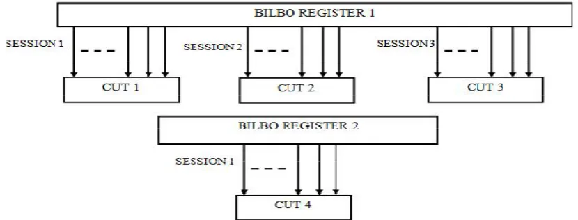
SCHEDULING METHODOLOGY:
Scheduling is applied to above test procedure in order to test four test circuits at a time. The scheduling method considered in this paper consists of three sessions. In first session, ripple carry adder and 1-bit full adder are tested. In second session, magnitude comparator and in third session, 32-bit ALU are tested respectively. The structure of scheduling methodology is shown in Figure 3.
Figure 3: Architecture of Scheduling methodology
RESULTS AND DISCUSSIONS:
The simulation results of above methodologies implemented on all test circuits are shown below. The proposed method derived less number of test patterns for all test circuits compared with number of patterns required in BILBO methodology.
BILBO METHODOLOGY:
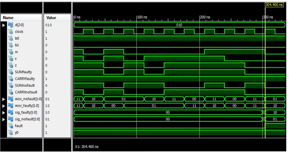
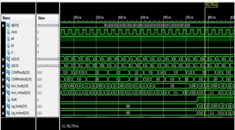
Figure 4 presents simulation result of BILBO methodology for 1-bit full adder.In the simulation, the signals “sig_faulty” and “sig_nofault” represents the signatures of both faulty and
Derived patterns Parent pattern Response from BILBO Fault simulation Phase shifter Fault simulation
IJSRR, 8(1) Jan. –March, 2019 Page 714 fault-free test-circuits respectively. The signal “fault” compares both signatures and it is enabled if both signatures differ with each other indicating that the circuit is faulty.
Figure 4: Simulation result of BILBO methodology for 1-bit full adder
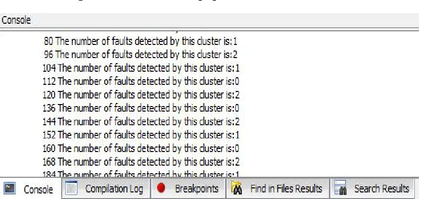
Figure 5: Console window of BILBO methodology for 1-bit full adder
IJSRR, 8(1) Jan. –March, 2019 Page 715
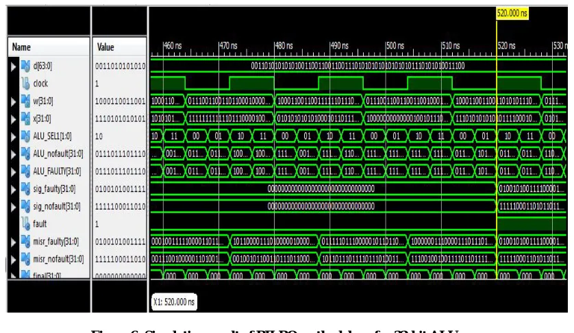
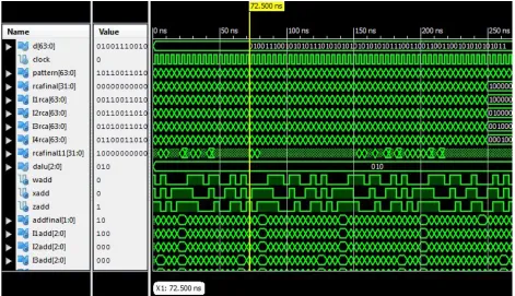
Figure 6: Simulation result of BILBO methodology for 32-bit ALU
IJSRR, 8(1) Jan. –March, 2019 Page 716
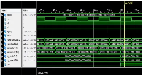
Figure 8: Simulation result of BILBO methodology for 32-bit Ripple carry adder
IJSRR, 8(1) Jan. –March, 2019 Page 717
Figure 10: Simulation result of BILBO methodology for 32-bit magnitude comparator
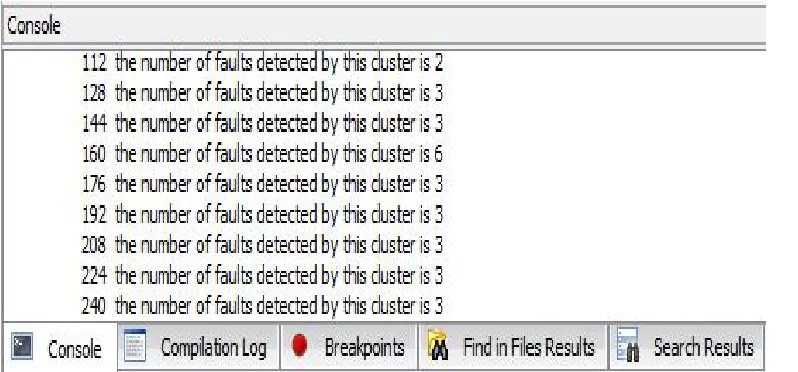
Figure 11: Console window of BILBO methodology for 32-bit magnitude comparator
PROPOSED METHOD
:IJSRR, 8(1) Jan. –March, 2019 Page 718
Figure 12: Simulation result of proposed method for 1-bit full adder
IJSRR, 8(1) Jan. –March, 2019 Page 719
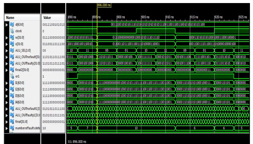
Figure 14: Simulation result of proposed method for 32-bit ALU
IJSRR, 8(1) Jan. –March, 2019 Page 720
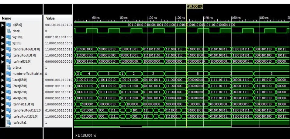
Figure 16: Simulation result of proposed method for 32-bit Ripple carry adder
IJSRR, 8(1) Jan. –March, 2019 Page 721
Figure 18: Simulation result of proposed method for 32-bit magnitude comparator
Figure 19: Console window of proposed method for 32-bit magnitude comparator
SCHEDULING METHODOLOGY:
32-IJSRR, 8(1) Jan. –March, 2019 Page 722 bit ALU are tested respectively.
Figure 20: Simulation result of Scheduling methodology for all sessions
IJSRR, 8(1) Jan. –March, 2019 Page 723
Figure 22: Simulation result of Scheduling methodology for session-2
Figure 23: Simulation result of Scheduling methodology for session-3
IJSRR, 8(1) Jan. –March, 2019 Page 724 are injected into the test-circuits. Whereas, BILBO with STAR-EDT derived less number of test patterns compared to BILBO methodology to detect all faults that are injected into test-circuits.
Table 1: Comparison between BILBO and proposed methodologies
TEST CIRCUIT
NUMBER OF FAULTS INJECTED
NUMBER OF PATTERNS REQUIRED IN BILBO
METHODOLOGY
NUMBER OF TEST PATTERNS DERIVED BY BILBO WITH STAR-EDT METHODOLOGY
1-BIT FULL ADDER 2 5 2
32-BIT ALU 10 6 1
32-BIT MAGNITUDE
COMPARATOR 7 5 3
32-BIT RIPPLE CARRY
ADDER 3 9 1
The proposed method derived minimum number of test pattern required to detect all faults that are injected into the test-circuits. The number of compressed test patterns are given in Table 1.
SCHEDULING METHODOLOGY:
Table 2: Scheduling applied to proposed methodology
TEST-CIRCUITS SESSIONS
TIME REQUIRED TO TEST ALL TEST-CIRCUITS IN
SCHEDULING
32-BIT RIPPLE CARRY ADDER SESSION-1
2.213 ns
1-BIT FULL-ADDER SESSION-1
32-BIT MAGNITUDE
COMPARATOR SESSION-2
32-BIT ALU SESSION-3
The scheduling methodology reduces the time required to test all test-circuits individually. Total time required to test all circuits is 2.213 ns only with three sessions. The process of scheduling and its sessions are given in Table 2.
CONCLUSION:
IJSRR, 8(1) Jan. –March, 2019 Page 725 scheduling methodology applied to BILBO with STAR-EDT reduces the time consumption by testing them parallelly.
REFERENCES:
1. GrzegorzMrugalski, JanuszRajski, Lukasz Rybak, Je¸drzejSolecki, and Jerzy Tyszer, “Star-EDT: Deterministic On-Chip Scheme Using Compressed Test Patterns”, IEEE Transactions On Computer-Aided Design of Integrated Circuits and Systems,April 2017; 36: 4.
2. Shaik Mohammed Waseem, Afroz Fatima, “Test Scheduling with Built in Logic Block Observer for NoC Architecture” International Conference on Innovative Mechanisms for Industry Applications (ICIMIA 2017).
3. S. Gayathri, V. SenthilKumaran, “Methodology to Detect and Diagnose Faults in Memories using BIST”, International Journal of Advanced Research in Computer and Communication Engineering, August, 2015; 4: 8.
4. Dong Xiang, Xiaoqing Wen and Laung-Terng Wang, “Low-Power Scan-Based Built-In Self-Test Based on Weighted Pseudorandom Self-Test Pattern Generation and Reseeding”, IEEE transactions on Very Large Scale Integration (VLSI) systems, March 2017; 25: 3.
5. Alpanasingh, Manassinghal, Vijay kumar, Priyankagupta and Pallavisexena, “BIST, Built-in-self- testing, A test technque” MIT International Journal of Electronics and Communication Engineering, August, 2012; 2(2) : 83-88.
6. Janusz Rajski, Jerzy Tyszer, Mark Kassab, and Nilanjan Mukherjee, “Embedded Deterministic Test”, IEEE Transactions On Computer-Aided Design of Integrated Circuits and Systems, May 2004; 23: 5.
7. Abdallatif S. Abu-Issa, “Energy-Efficient Scheme for Multiple Scan-Chains BIST Using Weight-Based Segmentation”, IEEE Transactions On Circuits and Systems—II: Express Briefs, March 2018; 65: 3.
8. Nandinipriya.M, Dr. (Mrs.) R.Brindha, “An Enhanced Architecture for High Performance BIST TPG”, IEEE Sponsored 2nd International Conference on Innovations in Information,Embedded and Communication systems (ICIIECS)2015.
9. G. Vamsi Krishna, G. SrinivasaRao, Y. Amar Babu, “Advanced Testing Methods for Reversible Logic”, International Journal of Applied Engineering Research ISSN 0973-4562, 2018; 13(7): 5484-5490.
IJSRR, 8(1) Jan. –March, 2019 Page 726 11.Yu Zhang, “Diagnostic Test Pattern Generation and Fault Simulation for Stuck-at and