Volume-6 Issue-2
International Journal of Intellectual Advancements
and Research in Engineering Computations
Instinctive foam cutting machine using PLC
Sasikumar.S1, Gowtham.R2, Parvathikrishnan.J3, Haribalaji.s4, Vigneshwaran.A5
1
Assistant Professor, 2,3,4,5UG Students, Department of Electronics and Instrumentation Engineering,
Nandha Engineering College, Erode, India.
ABSTRACT
To apprehend the solicitation and prominence of the participation of automation in conventional cutting machine in manufacturing. A cutting mechanism is available in various contours and sizes, with small hand-held power cutting systems and to bench mounted and finally floor-mounted models. This paper includes the categories of cutters, and shop formulas for setting up each operation. Human protection plays an acute part in any process involving power equipment. This paper also comprises techniques for maintaining, and proper setting up the work and methods of selecting various tools, and object holding devices to get a job done safely without causing damage to the equipment, human beings and surroundings.
Keywords: Foam cutting, Automation,
PLC based system
INTRODUCTION
This proposed system is based on Automation, Automation is basically the entrustment of human control functions to technical equipments intended towards accomplishing: Higher productivity, Superior quality of end product, Efficient usage of energy and raw materials, Improved safety in working conditions etc. This automation is made for industrial use in foam cutting. The main part of the proposed automation system is PLC. Programmable Logic Controller (PLC) is an industrial computer that monitors inputs, makes decision based on its program and controls outputs to automate a process or machine. RC network and SYNC motor are used for automation purpose.
A manual work system consists of one or more workers performing one or more tasks without the aid of powered tools. In a worker machine system, a human worker operates powered
equipment such as machine tool or other production machine. An automatic system is the system in which a process is performed by a machine without direct participation of a human being.
PROBLEMS
OF
CONSERVATIVE SYSTEMS
In olden days, cutting technology could not meet the needs of nifty cutting system. Generally, manual and semi-automated systems have severe reliability problems and very low productivity. Some problems
related to prevailing systems are as follows-
a) Production rate is low b) Non-continuous operation because of manual working takes more time c) Manual operation Start-up time is more d) Less production rate e) It cannot detect metal present in object f) Unsafe working due to more manual efforts. g) High maintenance
As the proposed system is based on automation, it will accentuate on it more. Before discussing on paper we would like to give a brief idea about automation. The automated elements of the production systems are separated in two categories- 1) Automation of the manufacturing systems in the industry
2) Computerization of the manufacturing systems
Automated manufacturing system are classified into three basic types:
1) Fixed automated systems
2) Programmable automated systems 3) Flexible automated systems
1) Fixed automated systems: These are the systems in which the sequence of processing operations which is to be carried out is fixed by the equipment configuration.
2) Programmable automated systems: In programmable automation, the machine is designed with the capability to change the sequence of operations to accommodate different product configuration
Fig 2: 3D view of foam cutting machine
COMPONENTS:
This project contains both hardware and software components
Hardware components consists of
1) PLC
2) Proximity sensor 3) Conveyor assembly 4) Control Panel 5) Cutting Setup 6) Limit Switch 7) Relay
8) Pneumatic cylinder
Hardware component description:
The proposed system consists of main conveyor assembly, cutter with motor arrangement, object detecting, pneumatic cylinder, proximity sensors and PLC. Here PLC is the main controller which will accept the inputs from proximity sensor, and then take control action on the conveyor, pneumatic cylinder and necessary cutting process assembly.
Pneumatic Setup: It is an assembly of pneumatic actuators integrated together with the help of mechanical assembly controlled through PLC via Solenoid valves. Pressurized air is supplied through air compressor.
Programmable Logic Controller (PLC): It is the main element of the system which is used to control the automated systems. It accepts the inputs from Proximity Sensor and gives controls the Pneumatic Setup, Conveyor and cutting motor.
Proximity Sensor: The proximity sensor is able to detect the presence of Foam object
without any physical contact. This sensor gives signals to PLC for taking the necessary control action.
Pneumatic cylinder: Pneumatic cylinder is a mechanical device which uses power of compressed gas or fluid used to control the movement of cutting blade.
Limit Switch: Limit switch is a switch operated by the motion of a machine part or presence of an object. It is used in controlling the machinery part of the control system with the help of PLC.
Relay: Relay is an electromechanical switch which is used when there must be electrical isolation when multiple circuits needs to be control by a single signal.
Conveyor Arrangement: It is used for carrying or moving the object from one location to another desired location.
Software component description:
Here we are using Delta PLC (Programmable Logic Controller) is an intelligent system, which was introduced in the instrumentation and control industry for replacing relay based logic. Nowadays, better I/O handling capabilities and more programming elements have been added along with improvement in communication. Basics of a PLC function is continuous scanning of a program. The scanning process involves three basic steps.
memory in order to be used in the following steps.
Programming execution: In this process PLC executes a program commands based on the program and based on the status of the input has obtained in the earlier step, and therefore action is taken. The action might be start of certain outputs and the results can be stored in memory to be rescued later in the following steps.
Output verification: Finally, a PLC performs outputs and adjust it as per need. Changes will be carried out based on the input status that had been read during the first step and based on the result of the program act in second step on execution of step three is done and PLC returns a beginning of the cycle and frequently repeats these steps. Scanning time = Time for performing step 1+ Time for performing step 2+ Time for performing step 3.
System working:
It is necessary to describe the proper sequence of operations which helps to run the system is successful manner. The sequence of operations can be described using narrative statements. These
statements describe what must happen in the system and in what way to achieve the
required result. The steps involved in this project are as follows:
1) Place the foam on the conveyer
2) Proximity sensor used to sense the object which is moving on conveyor
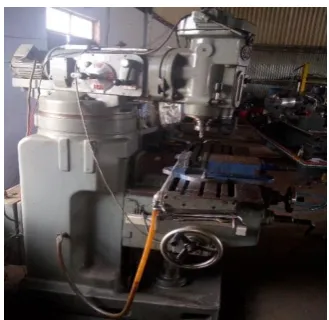
Fig 3. Foam Cutting Machine
Courtesy: Mechsoft Technologies
3) Limit switch 1 senses the signal of the conveyor belt and sends the signal to the PLC.
4) Limit switch 2 senses the signal of the cutting blade movements and sends the signal to the PLC.
5) If no foam is detected, the box proceeds towards cutting panel.
6) Sensor detects the foam and after some delay the conveyer stops. The pneumatic cylinder gets activated and clams the material.
7) The proximity switch sense that the material is clamped, the drilling motor starts and the motor moves in forward direction to bring the cutting motor in downward direction for cutting.
8) The foam is unclamped and conveyer starts again. Sensor acts as the feedback and the loop is repeated.
CONCLUSIONS
high productivity in short time period in comparison with the conventional foam cutting machine machines. The major advantage of this machine is intervention of labor is reduced to maximum level. This paper addresses the problem of automating the process of foam machining via the development of a robot-based flexible automated system that utilizes cutting blades. Thus, different work piece can be accommodated with just software and tooling changes. This feature is very advantageous when compared with the casting process of making foam. The developed methodology was applied for the cutting of automotive foam cutting. The results show that the automated system significantly reduces the cutting time and produces cuts of improved quality.
REFERENCES
[1] J. Buist and H. Gudgeon, Advances in Polyurethane Technology. Wiley, New York (1968).
[2] Y. Meltzer, Urethane Foams Technology and Applications. Noyes Data Corporation, Park Ridge, NJ (1971).
[3] K. Kawata, Y. Sawada and M. Yamashita, A new method of teaching and path generation for automatic die and mold polishing system, Proc. Japan~USA Symp. on Flexible Automation, ASME, p. 971 (1992).
[4] G. Boothroyd, Assembly Automation and Product Design. Dekker, New York (1992).
[5] S. Hirooka, I. Katanaya and S. Tanaka, Flexible automatic material handling system using guideless omni- directional vehicle, Proc. Japan~USA Symp. on
Flexible Automation, ASME, p. 917 (1992).
[6] D. Brienza, C. Brubaker, C. McLaurin and K. Chung, A manufacturing system for contoured foam cushions, J. Rehab. Res. Dev. 29(4), 32 (1992).
[7] D. Neth, T. McGovern and S. Roger, Computer aided measurement and fabrication of contoured body supports, Proc. 12th Ann. RESNA Conf., New Orleans, LA, 25-30 June. RESNA Press, Washington, DC, p. 234 (1989).
[8] I. Zeid, CAD/CAM Theory and Practice, Chapter 20. McGraw-Hill, New York (1991).
[9] J. Ferreira and S. Hinuja, A radial depth-based tool path generation method for pocket-machining, Trans. NAMRI/SME 21, 263 (1993).
[10] Rushikesh Gadale, Mahendra Pisal, Sanchit Tayade, S.V. Kulkarni, PLC based automatic cutting machine, IJETR, VOLUME 3, ISSUE 3(2015).