http://www.sciencepublishinggroup.com/j/ajam doi: 10.11648/j.ajam.20180605.12
ISSN: 2330-0043 (Print); ISSN: 2330-006X (Online)
Rotational Effect on Viscous Fluid Flow through
Rectangular Rotating Straight Duct
Nazmul Islam
1, *, Lasker Ershad Ali
1, Ariful Islam
21
Mathematics Discipline, Science, Engineering and Technology School, Khulna University, Khulna, Bangladesh
2Department of Chemical Engineering, Newcastle Institute for Energy and Resources, University of Newcastle, Newcastle, Australia
Email address:
*
Corresponding author
To cite this article:
Nazmul Islam, Lasker Ershad Ali, Ariful Islam. Rotational Effect on Viscous Fluid Flow through Rectangular Rotating Straight Duct.
American Journal of Applied Mathematics. Vol. 6, No. 5, 2018, pp. 159-166. doi: 10.11648/j.ajam.20180605.12
Received: October 8, 2018; Accepted: November 6, 2018; Published: December 18, 2018
Abstract:
In this paper, a numerical study has been done for fully developed laminar flow of an incompressible viscous fluid through a rotating straight duct with rectangular cross-section. The duct is rotated at a constant angular velocity around the vertical axis. The flow depends on the pressure driven parameter and the rotational parameter along with aspect ratio. The dimensionless non-linear equations are solved by using Spectral method where Chebyshev polynomial is adopted as a key tool. The calculations are carried out for different rotational parameter with a fixed aspect ratio at a constant pressure gradient parameter. The effect of rotational parameter has been observed for axial and secondary flows from the obtained results, which are shown in two dimensional contours and surface plots for axial flow whereas, two dimensional streamline plot, surface plot and vector plot for secondary flow. The asymmetry structure is seen in the axial flow pattern while the double vortex configuration is seen in the secondary flow structure, for all rotational parameter. However, the double vortex pattern in the secondary flow configuration is slightly compressed against the upper and lower walls of the duct for small rotational parameter, but it is highly compressed against the upper and lower walls for high rotational speed.Keywords:
Viscous Fluid, Steady Flow, Rotating Straight Duct, Rectangular Cross-Section and Pressure Gradient1. Introduction
Viscous fluid is a fluid which has the property of viscosity and which offers resistance to flow. In viscous fluid, due to the property viscosity, one layer of fluid resists the adjacent layer of fluid; as a result, we can see the parabolic velocity profile for the flow in a straight tube, involving the maximum fluid velocity along the centerline or tube axis. Fluid with low viscosity is low viscous fluid such as water while the fluid with high viscosity is high viscous fluid such as oil. For low viscous fluid, the Reynolds number is considered to be very high so that the convection term cannot be neglected in the equation of motion and the Navier-Stokes equation is considered in this scenario [1]. However, for high viscous fluid the Reynolds number is considered to be very low, as a result the convection term is neglected in the equation of motion and considered Stokes equation of motion in this case as the governing equation. In this research, the low viscous
fluid has been considered so that the Navier-Stokes equation and continuity equations have been considered as the governing equations of the flow problem.
Flow of a Newtonian fluid through an axi-symmetric straight pipe was first studied independently by Hagen and Poiseuille in the early 1800's. This type of flow gives the pressure drop in an incompressible and Newtonian fluid in laminar flow flowing through a long cylindrical pipe of constant cross-section. There are many studies expanding attention to include non-Newtonian flows [2], open channels [3], non-axi-symmetric tubes [4], tubes with corners and tubes with restrictions [5], to list but a few.
study the fluid flow in a rotating straight tube. There are many previous studies on fluid flow in a rotating straight tube. Barua [10], Benton and Baltimore [11], Islam et al. [12] studied theoretically the flow in a rotating straight pipe by using a perturbation expansion while Mori and Nakayama [13], Ito and Nanbu [14], Wanger and Velkoff [15] found good agreement with experiments. Numerical studies on fluid flow in a rotating straight tube was performed by Sharma and Nandakumar [16]. The fluid flow in a straight pipe with square cross-section was studied numerically by Kheshgi and Scriven [17], Nandakumar et al. [18] and Speziale [19] in case of square cross-sections. Zhang et al. [20] studied numerically the force dependent and time dependent transition of secondary flow in a rotating straight channel numerically by lattice Boltzmann method. For different forces, they have found 2-cells vortex in the secondary flow configuration. Some authors investigated fluid and heat transfer through rotating straight channel [21-24]. Since there is no detailed study regarding the flow in a rotating straight duct with rectangular cross-section of constant aspect ratio, it is quite useful and interesting to investigate the flow characteristics in rotating straight duct with rectangular cross-section at a constant aspect ratio.
Hence, the effects of rotation on the steady viscous fluid flow through a rotating straight duct with rectangular cross-section at a constant aspect ratio 2 is studied here numerically. Spectral Method has been used to obtain numerical solutions while the Chebyshev polynomial is used as a main tool [25-26].
2. Governing Equations
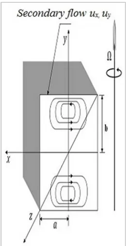
Consider the laminar flow of an incompressible viscous fluid in a rotating straight rectangular duct. The duct is rotated at a constant rate Ω about an axis which is perpendicular to the tube axis. The axial pressure gradient is given by −∂ ∂ =p′ z′ G and is considered to be constant, where p′ is the modified pressure which includes the gravitational and centrifugal forces. The physical configuration of the flow problem is shown in Figure 1.
Figure 1. Physical configuration of a rotating straight rectangular duct.
The flow is governed by the Navier-Stokes equation along with continuity equation that can be written in the following vector form:
2 1
( . ) 2
u
u u p u u
t ρ υ
′
∂ + ′∇ ′= − ∇ + ∇′ ′− Ω ∧ ′
∂ (1)
.u′ 0
∇ = (2)
where
2 2 2
2
2 2 2
x y z
∂ ∂ ∂
∇ = + +
′ ′ ′
∂ ∂ ∂ , u′ is the fluid velocity, p′
is the fluid pressure,ρ is the density of the fluid, υ µ
ρ = is
the kinematics viscosity and
Ω = Ω
j is the rotation rate ofthe duct.
In Cartesian coordinate system, the x, y and z components of equations (1) and (2) can be written as follows:
2 2 2
2 2 2
1
2
x x x x x x x
x y z z
u u u u p u u u
u u u u
t x y z ρ x υ x y z
′ ′ ′ ′ ′ ′ ′ ′
∂ + ′ ∂ + ′ ∂ + ′∂ = − ∂ + ∂ +∂ +∂ − Ω ′
′ ′ ′ ′
∂ ∂ ∂ ∂ ∂ ∂ ′ ∂ ′ ∂ ′ (3)
2 2 2
2 2 2
1
y y y y y y y
x y z
u u u u p u u u
u u u
t x y z
ρ
yυ
x y z
′ ′ ′ ′ ′ ′ ′
∂ + ′ ∂ + ′ ∂ + ′∂ = − ∂ ′+ ∂ +∂ +∂
′ ′ ′ ′
∂ ∂ ∂ ∂ ∂ ∂ ′ ∂ ′ ∂ ′ (4)
x z z z z z z y z x z
u
z
u
y
u
x
u
G
z
u
u
y
u
u
x
u
u
t
u
+
Ω
′
′
∂
′
∂
+
′
∂
′
∂
+
′
∂
′
∂
+
=
′
∂
′
∂
′
+
′
∂
′
∂
′
+
′
∂
′
∂
′
+
∂
′
∂
2
2 2 2 2 2 2υ
ρ
(5)0 = ′ ∂ ′ ∂ + ′ ∂ ′ ∂ + ′ ∂ ′ ∂ z u y u x
ux y z
(6) where
u , u , u
x′ ′ ′
y z are the velocity components of u along x, y, z directions respectively.0
=
′
=
′
=
′
xu
yu
zu
on the wall of the straight pipe. The fully developed flow has been considered so that except for the pressure derivative, allz
′
derivatives are zero. Again, for steady flow the rate of change of velocity is zero, i.e.,0
y
x u x
u u
t t t
′ ∂
′ ′
∂ = =∂ =
∂ ∂ ∂ Then, the dependent and independent
variables can be made non-dimensional as follows:
x x y y
u u ,u u ,
a a
υ υ
′ = ′ = u′z=υau ,xz ′=xa, y′=ya, z′=za,
2 2 p p a υ ρ ′ = ,
where primes indicate dimensional quantities and a is the half width of the duct cross-section.
By using the above assumptions, the non-dimensional equations of the governing equations (3) - (6) are in the following form:
2 2
2 2
x x x x
x y z
u u p u u
u u Ru
x y x x y
∂ + ∂ = −∂ + ∂ +∂ −
∂ ∂ ∂ ∂ ∂ (7)
∂
∂
+
∂
∂
+
∂
∂
−
=
∂
∂
+
∂
∂
2 2 2 2y
u
x
u
y
p
y
u
u
x
u
u
x y y y y y (8)x z z n z y z x
Ru
y
u
x
u
P
y
u
u
x
u
u
+
∂
∂
+
∂
∂
+
=
∂
∂
+
∂
∂
2 2 2 2 (9)0
=
∂
∂
+
∂
∂
y
u
x
u
x y(10)
Where
(
Ga3ρυ
2)
=Pn is the pressure driven parameter and 2(
a2Ω υ
)
=Ris the rotation parameter.The no-slip boundary condition implies that velocity is zero on the tube wall, i.e., at
x
=
±
1
,y
=
±
σ
, whereσ
is the aspect ratio which is defined asσ
=
( )
b
a
, here b be the half height of the cross-section.With the help of aspect ratio, a new variable is introduced as
y
=
( )
y
σ
. Substituting the values ofu
x=
−
(
∂
ψ
∂
y
)
andu
y=
(
∂
ψ
∂
x
)
into equations (7) and (8) and then by cross differentiation of these two equations, the basic equations for the stream functionψ
and for the axialvelocity
u
zare as follows:y
w
R
y
x
x
y
x
y
x
y
x
y
y
x
y
x
∂ ∂ − ∂ ∂ ∂ ∂ ∂ + ∂ ∂ ∂ ∂ − ∂ ∂ ∂ ∂ + ∂ ∂ ∂ ∂ ∂ − = ∂ ∂ + ∂ ∂ ∂ + ∂ ∂σ
ψ
ψ
σ
ψ
ψ
σ
ψ
ψ
σ
ψ
ψ
σ
ψ
σ
ψ
σ
ψ
2 3 3 3 3 3 3 2 3 3 4 4 4 2 2 4 2 4 4 1 1 1 1 1 2 (11) n z z z zP
y
R
x
u
y
y
u
x
y
u
x
u
−
∂
∂
+
∂
∂
∂
∂
−
∂
∂
∂
∂
=
∂
∂
+
∂
∂
ψ
σ
ψ
σ
ψ
σ
σ
1
1
1
2 2 2 2 2 (12)The boundary conditions for the stream function
ψ
and for the axial velocity w are given by(
1
)
(
1
) (
1
)
0
z z
u
= ±
, y
=
u x,
± =
ψ
±
, y
=
,(
∂ ∂ ±
ψ
x
)(
1
, y
)
=
ψ
(
x,
± = ∂ ∂
1
) (
ψ
y
)(
x,
± =
1
)
0
.3. Numerical Calculation Techniques
Spectral method is used for the numerical calculations and Chebyshev polynomial is used as a tool. Here, the axial velocity
u
z=
( )
x
,
y
and the stream functionψ
( )
x, y
have been expanded as follows:( )
( )
0 0
M N
z mn z
m n
u x, y c u x, y
= = =
∑∑
,( )
( )
0 0 M N mn m nx, y x, y
ψ ψ ψ
= =
=
∑∑
,( )
( )(
1 2 1 2)
( ) ( )
z m n
u x, y = −x −y U x U y and
( )
2 2 2 21 1 m n
x, y ( x ) ( y ) U ( x )U ( y )
ψ
= − − , where M and Nare the truncation numbers along x and
y
directions respectively,U
m andU
nare the corresponding m-th and n -th order Chebyshev polynomials. The collocation me-thod is used to get the equations for the coefficientsc
mn andψ
mn where the collocation points are taken as follows:1 1 1 1
2 2
i j
i j
x cos , ( i ,...M ), y cos , ( j ,...,N )
M N π π = = + = = + + + .
For the convergence
ε
k<
10
−10 has been taken, whereε
k is defined as{
( k 1) k} {
2 ( k 1) k}
2k cmn cmn mn mn
ε = + − + ψ + −ψ
∑∑
.The truncation numbers in the x and
y
directions are taken as M=16 and N=32 for the numerical calculations. In this research, the program has been written in Intel Visual4. Results and Discussions
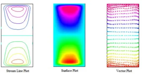
The fully developed flow of viscous fluid has been investigated in a rotating straight duct with rectangular cross-section for a constant aspect ratio 2. The left hand figure shows contour plot while the right hand figure shows the surface plot in the axial flow Figure In the secondary flow, the left hand figure shows the streamline plot while the right hand figure shows the vector plot, and the surface plot is shown in the middle of these two plots. It is noted that in two dimensional plots, the outer wall is to the right and the inner wall is to the left. The arrow in the vector plots always indicates the direction of the flow. As a result, the strength of the flow is not clearly understood in the very weak secondary flow region.
As mentioned earlier, the flow is governed by the pressure gradient and the tube is rotated about an axis which is perpendicular to the duct axis. According to the definition of rotation parameter , the positive rotation means that the rotation direction is in the same as the main. Positive rotation is considered in our investigation. The calculations have been done in different rotational parameters within the range
1≤ ≤R 76 for the fixed aspect ratio σ =2 with rectangular cross-section and the constant pressure driven parameter
100
n
P = .
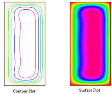
Figures 2, 4, 6, 8, 10, 12, 14, 16, 18, 20 represent the axial flow patterns in the form of contour and surface plots. The left part of the Figure 2 shows the contour plot whereas; the right one represents the surface plot for the axial flow at the rotational parameter R=1. From the contour plot in this figure, it has been seen that the contour line patterns of the axial flow is the same for every curve. The surface plot in this figure shows the axial flow strength in different domains within the duct. The red region indicates the maximum axial flow region which is around the center line. The axial flow strength decreases from the center line towards the duct wall, which has been represented by different colors. It is also observed from this figure that the axial flow (contour plot, surface plot) patterns are highly asymmetric along the horizontal line of the duct and the maximum value has been shifted towards the low pressure region (top and bottom walls). Similar effects can be observed from Figures 4, 6, 8, 10, 12, 14, 16, 18 and 20.
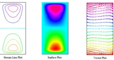
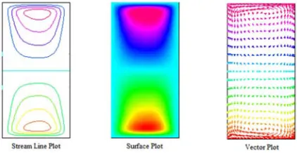
The even Figures 3, 5, 7, 9, 11, 13, 15, 17, 19 and 21 depict the secondary flow structure in the form of streamline plot, surface plot and vector plot accordingly. In Figure 3, the left part shows the streamline plot while the right hand part shows the vector plot and the middle one is the surface plot. The streamline plot, surface plot and the vector plot in this figure clearly show two portions of the secondary flow which consist of a counter rotating vortices, one vortex is located at the upper (rotates in the anti-clockwise direction) and another one at the lower (rotates in the clock-wise direction) wall of the duct. The direction of each vortex can be seen from the vector plot in Figure 3. For moderate and slightly more rapid rotations, the double vortex secondary flow (streamline plot, surface plot and vector plot) is slightly compressed against the upper and lower wall of the duct which can be viewed in
Figures 5 and 7, respectively. If the rotation rate is increased further, the vortices begin to stretch into the interior of the duct which has been observed in Figures 9, 11, 13, 15, 17, 19 and 21. The existence of the double vortices flow structure can be confirmed from the results of the secondary flow figures, where each vortex is somewhat compressed against the wall of the duct.
Figure 2. Contour plot, surface plot of the axial flow for rotating straight duct of rectangular cross-section at R=1 and aspect ratio =2 with pressure driven parameter Pn =100.
Figure 3. Streamline plot, surface plot, and vector plot of the secondary flow for rotating straight duct of rectangular cross-section at R=1 and aspect ratio =2 with pressure driven parameter Pn =100.
Figure 5. Streamline plot, surface plot, and vector plot of the secondary flow for rotating straight duct of rectangular cross-section at R=10 and aspect ratio =2 with pressure driven parameter Pn =100.
Figure 6. Contour plot, surface plot of the axial flow for rotating straight duct of rectangular cross-section at R=20 and aspect ratio =2 with pressure driven parameter Pn =100.
Figure 7. Streamline plot, surface plot, and vector plot of the secondary flow for rotating straight duct of rectangular cross-section at R=20 and aspect ratio =2 with pressure driven parameter Pn =100.
Figure 8. Contour plot, surface plot of the axial flow for rotating straight duct of rectangular cross-section at R=30 and aspect ratio =2 with pressure driven parameter Pn =100.
Figure 9. Streamline plot, surface plot, and vector plot of the secondary flow for rotating straight duct of rectangular cross-section at R=30 and aspect ratio =2 with pressure driven parameter Pn =100.
Figure 10. Contour plot, surface plot of the axial flow for rotating straight duct of rectangular cross-section at R=40 and aspect ratio =2 with pressure driven parameter Pn =100.
Figure 11. Streamline plot, surface plot, and vector plot of the secondary flow for rotating straight duct of rectangular cross-section at R=40 and aspect ratio =2 with pressure driven parameter Pn =100.
Figure 13. Streamline plot, surface plot, and vector plot of the secondary flow for rotating straight duct of rectangular cross-section at R=50 and aspect ratio =2 with pressure driven parameter Pn =100.
Figure 14. Contour plot, surface plot of the axial flow for rotating straight duct of rectangular cross-section at R=60 and aspect ratio =2 with pressure driven parameter Pn =100.
Figure 15. Streamline plot, surface plot, and vector plot of the secondary flow for rotating straight duct of rectangular cross-section at R=60 and aspect ratio =2 with pressure driven parameter Pn =100.
Figure 16. Contour plot, surface plot of the axial flow for rotating straight duct of rectangular cross-section at R=70 and aspect ratio =2 with pressure driven parameter Pn =100.
Figure 17. Streamline plot, surface plot, and vector plot of the secondary flow for rotating straight duct of rectangular cross-section at R=70 and aspect ratio =2 with pressure driven parameter Pn =100.
Figure 18. Contour plot, surface plot of the axial flow for rotating straight duct of rectangular cross-section at R=75 and aspect ratio =2 with pressure driven parameter Pn =100.
Figure 19. Streamline plot, surface plot, and vector plot of the secondary flow for rotating straight duct of rectangular cross-section at R=75 and aspect ratio =2 with pressure driven parameter Pn =100.
Figure 21. Streamline plot, surface plot, and vector plot of the secondary flow for rotating straight duct of rectangular cross-section at R=76 and aspect ratio =2 with pressure driven parameter Pn =100.
5. Conclusion
In this paper, the fully developed laminar flow of viscous incompressible fluid has been investigated through a rotating straight duct for the different values of rotational parameter with a fixed aspect ratio and pressure driven parameter. For small rotational parameters, the asymmetry structure is visualized in the axial flow patterns while merely symmetric structure is observed for high rotation rate. The axial flow patterns are highly asymmetric along the horizontal line of the duct and the maximum value has been shifted towards the low pressure region. The axial flow strength decreases from the center line towards the duct wall. The double vortex patterns have been found in the secondary flow configurations for every rotational parameter. For moderate rotation rate, the double vortex secondary flow is slightly compressed against the upper and lower wall of the duct while the secondary flow vortices begin to stretch into the interior of the duct for high rotation rate. The increment of numerical value of the contour line of the axial flow or streamline of secondary flow is the same for every curve. In this numerical study, only two vortices have been found in the flow configurations for the fixed aspect ratio 2. However, more vortices can be observed in the flow configuration for variable aspect ratios which can be investigated in future.
References
[1] Batchelor, G. K. An Introduction to Fluid Dynamics, Cambridge University Press, Cambridge, 1967.
[2] Rothstein, J. P. and McKinley, G. H., (2001) The axisymmetric contraction/expansion: the role of extensional rheology on vortex growth dynamics and the enhanced pressure drop, Journal of Non-Newtonian Fluid Mechanics, 98: 33-63.
[3] Subramanya, K. Flow in Open Channels, Tata McGraw-Hill Education, 1982.
[4] Mills, Z. G., Shah, T., Warey, A. and Balestrino, S., (2014) Onset of unsteady ow in wavy walled channels at low Reynolds number, Physics of Fluids, 26: 084-104.
[5] Mofatt, H. K., (1964) Viscous and resistive eddies near a sharp corner, Journal of Fluid Mechanics, 18: 1-18.
[6] Duck, P. W., (1983) Flow through rotating straight pipes of circular cross-section, Physics of FluidsA, 26(3): 614-618. [7] Mansour, K., (1985) Laminar flow through a slowly rotating
straight pipe, Journal of Fluid Mechanics,150: 1-21.
[8] Lei, U. and Hsu, C. H., (1990) Flow through a straight pipe,
Physics of FluidsA, 2(1): 63-75.
[9] Ishigaki, H., (1994) Analogy between laminar flows in curved pipes and rotating pipes, Journal of Fluid Mechanics, 268: 133-145.
[10] Barua, S. N., (1995) Secondary flow in rotating straight pipe,
Proceeding of Royal Society of London A, 227: 133-139. [11] Benton, G. S. and Baltimore, M. D., (1956) The effect of the
earth’s rotation on laminar flow in pipes, Journal of Applied Mechanics,March Issue: 123-127.
[12] Islam, N., Shameem, S. M., Rahman, M. A., and Alam, M. M., (2004) Flow through a rotating straight pipe, Journal of Mathematics and Mathematical Science, 19: 21-33.
[13] Mori, Y. and Nakayama, W., (1965) Study on Forced Convective Heat Transfer in Curved Pipes, International Journal of Heat and Mass Transfer, 8: 67-82.
[14] Ito, H. and Nanbu, K., (1971) Flow in rotating straight pipes of circular cross-section, ASME Journal of Basic Engineering, September Issue:383-394.
[15] Wanger, R. E, Velkoff, H. R., (1972) Measurements of secondary flows in a rotating duct. Journal of Engineering for Power, 94(10): 261–270.
[16] Sharma, R. K. and Nandakumar, K., (1995) Multiple, two– dimensional solution in a rotating straight pipes, Physics of Fluids A, 7(7): 1568-1575.
[17] Kheshgi, H. S. and Scriven, L. E., (1985) Viscous flow through a rotating square channel, Physics of Fluids A, 28(10): 2968-2985.
[18] Nandakumar, K., Raszillier, H. and Durst, F., (1991) Flow through rotating rectangular ducts, Physics of Fluids A, 3(5): 770-781.
[19] Spezial, C. G., (1982) Numerical study of viscous flow in a rotating system, Journal of Fluid Mechanics, 122: 251-271.
[20] Zhang, J., Liu, Y., Zhang, J. and Yang, J., (2009) Study of force-dependent and time-dependent transition of secondary flow in a rotating straight channel by the lattice Boltzmann method, Physica A: Statistical Mechanics and its applications, 388(4): 288 - 294.
[21] Lei, U. and Yang, A. C. Y., (2001) Convective Heat Transfer of the Flow through a Rotating Circular Straight Pipe, Journal of Mechanics, 17(2): 79 – 91.
[22] Roy, P., Anand, N. K. and Banerjee, D., (2013) Numerical simulation of flow and heat transfer in radially rotating microchannels, Microfluidics and Nanofluidics, 15(3): 397 – 413.
[24] Kanikzadeh, M. and Sohankar, A., (2016) Thermal performance evaluation of the rotating U-shaped micro/mini/macrochannels using water and nanofluids,
Numerical Heat Transfer, Part A: Applications, 70(6): 650-654.
[25] Canuto, C., Hussaini, M. Y., Quarteroni, A. and Zang, T. A., Spectral methods in fluid dynamics, Springer-Verlag, Berlin, 1988.