Geotechnical Engineering Design of a Tunnel
Support System - A Case Study of Bheri
Babai Headrace Tunnel
Deepika Ghorasaini#1, Akal Bahadur Singh*2
#1
Student, M.Sc. in Geotechnical Engineering, Institute of Engineering, Tribhuwan University, Nepal *2
Professor, Department of Civil Engineering, Institute of Engineering, Tribhuwan University, Nepal
Abstract
The analysis of rock mass strength, geological problem related to tunnel construction and designing appropriate support system for Bheri Babai Headrace Tunnel (BBDMP) is presented in the paper. Tunnel squeezing and rock burst is checked before design of support system. Rock mass classification system (Q and RMR) are used as empirical method to obtain recommended support system. For analytical solution Convergent confinement method is used to determine required support pressure to resist displacement. Finite element modelling using Phase 2 version 7.013 is used to check the ground condition and stress concentration around the tunnel providing support systemfor resisting the deformation. The displacement and radius of plastic zone is reduced after installation of support shown by obtained results. The first two method i.e. empirical and analytical provide first estimate to design while numerical method can be used to verify the performance of support system. Hence design method providing maximum factor of safety should is recommended.
Keywords - Tunnels, Case study, Support, Squeezing, Rock burst, Empirical Method, Analytical Method, Numerical Modelling
I. INTRODUCTION
Tunnels are flexible structures during construction of any infrastructure. Tunnel prove to be the shortest alignment proving more efficient and effective medium of construction. Due to the short route and economic feasibility most of the hydropower tunnels of Nepal choose tunnels for water conveyance. With ease comes challenges, on the other hand various hazards are associated with underground construction. Some of them are swelling, squeezing, rock burst, spalling etc which are major problems faced during underground tunnelling in weak rocks. Tunnelling in weak rocks is an iterative process. The impending failure that may arise due to the construction of tunnel is resisted by proper designing of tunnel support system.
The aim of this paper is to analyse the geological condition and to obtain required support system. Bheri Babai Headrace Tunnel is the first tunnel to be built on Siwalik region of Nepal. The BBDMP aims
to divert 40 m3/s of water from Bheri River to the Babai River to irrigate 51,000 ha of agricultural land of Bardia and Banke district of Nepal and also thereby generate 48 MW of electricity making it a multipurpose project. The tunnel alignment lies in Surkhet and Bardia district of Nepal. The Tunnel is divided into six sections.[1]
The overburden, Q and RMR value of the sections are presented below:
TABLE 1:Input data for Bheri Babai headrace tunnel Chainage Overburden
(m)
RMR Q
1+600 560 31 2.4
2+800 618.3 41 2.8
5+300 408.5 56 4.5
6+200 346.6 29 1.5
8+400 132.8 35 2.6
12+200 120 44 4.3
Since the chainage 6+200m has least RMR and Q value and Bheri Thrust also lies in this regionso the design of this section is presented in this paper.
II. TUNNELLINGPROBLEMS
Among various hazards to be faced during construction of tunnel squeezing and rock burst is among them. According to ISRM squeezing of rock is the time dependent large deformation which occurs around a tunnel and other underground openings and is essentially associated with creep caused by exceeding shear strength (limiting shear stress). Experience shows that deeper an opening is made in rocks; more vulnerable it becomes to rock burst. The rock burst is defined as any sudden and violent expulsion of rock pieces from an apparently stable opening. [2]
value with SRF 1. The summary for this method is shown below.
TABLE 2:Summary of squeezing criteria of Empirical Approach
Approach Squeezing condition
Non-squeezing condition Singh’s
approach
H <350Q1/3 H >350Q1/3
Goel’s approach
H<(275N0.33) B0.1 H> (275N0.33) B0.1
Among various semi-empirical method to determine tunnel squeezing Jethwa.et.al (1984) approach is used to check the tunnel squeezing. The uniaxial compressive strength and in-situ stress is considered during the analysis. The summary for this method is shown is in table.
TABLE 3:Summary of squeezing criteria according to Jethwa et al. (1984) [5]
Nc Condition
<0.4 Highly squeezing
0.4-0.8 Moderately Squeezing
0.8-2.0 Mildly Squeezing
>2.0 No Squeezing
Criteria for rock burst was checked using empirical approaches by Hoek and Brown and Grimstad and Barton.
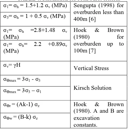
TABLE 4:Calculation for rock burst criteria σ1= σh = 1.5+1.2 σv (MPa) Sengupta (1998) for
overburden less than 400m [6]
σ3= σh = 1 + 0.5 σv (MPa)
σ1= σh =2.8+1.48 σv (MPa)
Hoek & Brown
(1980) for
overburden up to 100m [7]
σ1= σh= 2.2 +0.89σv (MPa)
σv= γH
Vertical Stress
σϴmax = 3σ1 - σ3
Kirsch Solution σϴmax = 3σ3 – σ1
σϴr = (Ak-1) σz Hoek & Brown (1980). A and B are excavation
constants. σϴw = (B-k) σz
III.TUNNEL SUPPORT DESIGN USING
EMPIRICAL APPROACH
Q-system is very common for rock mass classification for tunnelling. The other system used in the research paper is Rock Mass Rating (RMR) system. According to Q system the rock mass classification is Poor rock for the section considered. According to RMR system the classification is also
Poor. The chart provided by Barton is used todetermine the support required for the tunnel.
IV.TUNNEL SUPPORT DESIGN USING
ANALYTICAL APPROACH
The method is also known as Convergent Confinement Analysis which determines displacement of the tunnel and gives the support pressure that can control the displacement. Carranza-Torres and Fairhust said CCM has three components: Longitudinal Displacement Profile (LDP), Ground reaction Curve and SCC.[8]
A. Longitudinal Displacement Profile
LDP is the graphical representation of radial displacement that occurs along the axis of unsupported cylindrical excavation i.e. for the sections located ahead of and behind tunnel face.
B. Ground Reaction Curve
GRC is the relationship between decreasing internal pressure pi and increasing radial displacement of tunnel wall ur. The Relationship depend upon mechanical property of rock mass and can be obtained from the elasto-plastic solution of rock deformation around an excavation.
C. Support Characteristics Curve
Support characteristics curve is the plot between increasing pressure Ps on the support and increasing radial displacement ur of the support.
V. CALCULATION OF AVAILABLE SUPPORT
A. Available support for shotcrete or concrete lining
The maximum support pressure developed by concrete or shotcrete lining can be calculated from the following relationship which is based on the theory of hollow cylinders.
psmax= σcc
2 1 −
(R−tc)2
R2
The stiffness constant Ks is as follows:
Ks= Ec
1− υC R
R2−(R−tc)2
1− υC R2+(R−tc)2 Where,
Ec elastic modulus of concrete υc is Poisson’sratio
R is external radius of tunnel (m) tc is thickness of the concrete orshotcrete
σcc is unconfined compressive strength of the shotcrete or concrete
B. Available support for ungrouted bolts and cables
The maximum pressure provided by the support system, assuming that the bolts are equally space in the circumferential direction, is given by:
psmax = Tbf scsl
And the stiffness is given by: 1
Ks = scsl 4l
l is the free length of bolt or cable (m)
Tbf is the ultimate load obtained from a pullout test (MN)
Q is a deformation load constant for the anchor and head (m/MN)
Es is Young’s modulus of bolt or cable (MPa) Sc is the circumferential bolt spacing (m) Sl is the longitudinal bolt spacing (m)
C. Available Support for SteelSet
The maximum support pressure of the set is: psmax = Asσy
scR And the
stiffness is: K = SRE2
Where,
σyis yield strength of steel (MPa)
Es is the Young’s modulus of the steel (MPa) As is the cross-sectional area of the section (m) Sc is the set spacing along the tunnel axis(m) R is the radius of the tunnel (m)
In this case, the stiffness of the combined system is determined as the sum of the stiffness of the individual components.
K = K1 + K2
Where, K1= stiffness of the first system and K2= stiffness of the second system.
VI.TUNNEL SUPPORT DESIGN USING
NUMERICAL MODELLING
Numerical methods available for problem solving in geotechnical engineering are Finite Element Method (FEM), Spectral Element Method (SEM), Finite Difference Method (FDM), Finite Volume Method (FVM), Discrete Element Method (FEM). [10]
Finite Element Method (FEM) is a technique which approximates the solution of governing differential equations in the mathematical model by dividing the domain into meshes or grids and applying simpler equations to individual elements or nodes in the mesh to approximate the solution by minimizing the associated error function. [11]
Phase2is a two-dimensional elasto-plastic finite element program. It is used for calculating stresses and displacements around underground openings, and can be used to solve a wide range of mining, geotechnical and civil engineering problems. The detail assessment is using computer software is carried out for chainage 6+200m. The properties are adopted as much as possible to real values. The blast damage factor was introduced in Hoek and Brown failure criterion in 2002, the constant is determined as follows.[12]
mb = mi exp GSI −10028−14D
s = exp GSI −100
9−3D
a = 1
2+ 1 6 (e
−GSI /15- e−20/3)
The GSI Value is calculated using following relation: GSI = RMR – 5
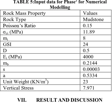
TABLE 5:Input data for Phase2 for Numerical Modelling
Rock Mass Property Values
Rock Type Mudstone
Poisson’s Ratio 0.15
σci (MPa) 11.89
mi 8
GSI 24
D 0.5
Ei (MPa) 4000
mb 0.2144
s 0.00003
a 0.5334
Unit Weight (KN/m3) 23
Vertical Stress 7.971
VII. RESULT AND DISCUSSION
Assessment for Squeezing and Rock Burst Condition was done for Chainage 6+200m.
TABLE 6: Checking of squeezing criteria for chainage 6+200m
Goel Approach
Singh Approach
Jethwa et. al approach
Squeeze Safe Mild squeeze
TABLE 7: Checking for rock burst for chainage 6+200m
σc / σϴ For Roof For Wall
Hoek and
Brown
Severe Spalling
Heavy support Required Grimstad and
Barton [9]
High stress, Usually favourable to stability
Moderate Slabbing After 1 hour
The support was designed considering the above condition for squeezing and rock burst. The empirical, analytical and numerical modelling for the section was performed.
A. Empirical Method
The support system as suggested by Q and RMR System is given in table below.
TABLE 8:Support system suggested by Q System
Bolts Shotcrete Steel Sets
25 mm diameter 2.5 mm long grouted rock
7.5 cm thick steel fibre reinforced shotcrete
None
TABLE 9: Support system suggested by RMR System
Systematic Bolts 4-5m long, spaced 1-1.5 m in crown and wall with wire mesh.
100-150mm in crown and 100 mm in sides.
Light to medium ribs spaced 1.5 m where required.
B. Analytical Method
Ground reaction curve and Support reaction curve was prepared for the section. Factor of Safetyof 2.09 was obtained after combined bolt, shotcrete and steel sets was provided.
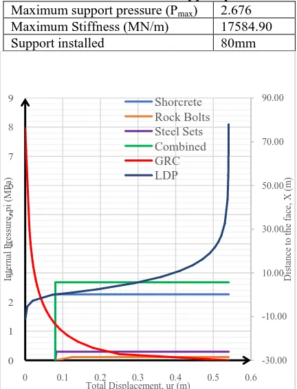
TABLE 10: Total combined support parameters
Maximum support pressure (Pmax) 2.676 Maximum Stiffness (MN/m) 17584.90
Support installed 80mm
FIGURE 1:GRC, LDP and SCC for chainage 6+200m
C. Numerical Modelling (PHASE2)
The displacement after preparing the model was seen 75 mm. The radius of plastic zone was 32m. So,in order to reduce the plastic zone and displacement support was installed. Care is taken the tunnel closure is not more than 4% of the tunnel span. Support capacity diagram is generated for determining the factor of safety of shotcrete and steel ribs. For a given factor of safety, capacity envelopes are plotted in axial force versus moment space and axial force versus shear force space. Values of axial force, moment and shear force for the liners are then compared to the capacity envelopes. The computed liners values must fall inside an envelope so that they have a factor of safety greater than envelope values. Factor of Safety greater than 2 is accepted. Also, there should be no yielding of bolts and liners.
TABLE 11: Support system suggested by Phase2
Steel Ribs (I Beam M Type)
Shotcrete
Sectional depth
0.203m Thickness 300mm
Area 0.0012
m2
Poisson Ratio
0.25
Youngs Modulus
2 × 10⁵ MPa
Compressive Strength
25 MPa Poisson
Ratio
0.25 Tensile Strength
3 MPa
Compressive Strength
250 MPa Rock-Bolts (Fully Bonded, 3m long)
Tensile Strength
400 MPa Diameter 25 mm
Weight 8.9
Kg/m
Bolt Modulus
2 × 10⁵ MPa
FIGURE 2: Total displacement 75mmand Radius of plastic zone 32.6m before support installation
FIGURE 3:Total displacement 18.51mm and Radius of plastic zone 9.171m after support installation
VIII. CONCLUSION
Empirical method gives very low value of support system. Analytical method provides quite fair result but cannot meet the permissible requirement. Integrating empirical, analytical and numerical
-30.00 -10.00 10.00 30.00 50.00 70.00 90.00
0 1 2 3 4 5 6 7 8 9
0 0.1 0.2 0.3 0.4 0.5 0.6
D
is
tan
ce
to
t
h
e
face,
X
(m
)
In
tern
al
Pres
su
re,
p
i
(MPa)
Total Displacement, ur (m)
modelling, a satisfactory support can be achieved. The result form Phase modelling show displacement and radius of plastic zone reduces significantly after installation of support. The analytical GRC and SCC helps to determine the appropriate time to install the support. The empirical and analytical method lead to determine first estimate of ground behaviour while numerical modelling can be used to verify the performance of the excavated ground. So, recommending the support as suggested in Table 11.
ACKNOWLEDGMENT
The authorsgive sincere thanks to Institute of Engineering, Tribhuwan University for the encouragement and MSc. Geotechnical Engineering coordinator Dr.Indra Prasad Acharya for his constant help during publication of this paper. The authorsare obliged to Department of Irrigation for providingwith data required for completing the research.
REFERENCES
[1] www.bbdmp.gov.np
[2] Singh, B., & Goel R. (2006). Tunnelling in weak rocks.
Elsevier.
[3] Singh, B., Jethwa J., & Dube A. (1992). Correlation between
observed support pressure and rock mass quality. Tunnelling and Underground Space Technology.
[4] Goel, R., Jethwa, J., & Paithanakar, A. (n.d), Indian
experience with Q and RMR systems, Tunnelling and Underground Space Technology.
[5] Jethwa J., &Singh B. (1984). Estimation of ultimate rock
pressure for tunnel linings under squeezing rock conditions- a new approach. Design and Performance of Underground Excavations (pp. 231-8), Cambridge: ISRM.
[6] Sengupta, S. (1998). Influence of geological structures on In
Situ Stresses. Uttarakhand, India: Department of Civil Engineering, IIT.
[7] Hoek, E.,& Brown, T. (1980). Underground Excavations in
Rock. Institution of Mining and Metallurgy, (p.527). London.
[8] Carranza-Torres C., & Fairhust, C. (2000). Application of
Convergence-Confinement method of tunnel design to rock masses that satisfy Hoek-Brown Failure Criterion. Tunnelling and Underground Space Technology.
[9] Grimstad, E., Barton, N. (1980). Updating the Q system for
NMT. International Symposium on Sprayed Concrete. Oslo Norway: Norwegian Concret e Association Atkinson, K.E. (2007). Numerical Analysis. Scholarpedia
[10] Zadeh, A., & Tackley, P. (2011). Computational methods for
geodynamics. Geophysical Journal International.
[11] Hoek, E., Carranza-Torres, C., & Corkum, B. (2002).
Hoek-Brown Failure criterion – 2002 Edition, NARMS-TAC Conference, Toronto.
[12] M.S Rahul (2014). Case study on design and construction of
tunnel.International Journal of Engineering Trends