Abstract
To study design and winding technique of linear induction motor. The purpose of this project is to increase use of LIM in industry for transportation purpose. The low rating LIM are of low cost, low energy consumption, high speed, and low pollution. The project will shows prototype of Linear Induction Motor as a drive which carry 10-15kg weight in which flat rotor move forward direction
I. INTRODUCTION
Single-sided linear induction motor it is used in transportation. The reason why it is selected the LIM for transportation is the low energy consumption, high speed, and low pollution. Electrical energy converts into mechanical energy and linear motion is achieved. In recent years, there have been more than 20 urban transportation lines propelled by single-sided linear induction motors (SLIMs) among the world, such as the Kennedy air line in America, linear metro in Japan, Vancouver light train in Canada, Guangzhou subway line 4 in China, and so on. The primary, similar to the stator of a induction machine (RIM), is hanged below the redirector, which is supplied by the inverter on the vehicle. The secondary, corresponding to the rotor of RIM, is flatted on the railway track, which usually consists of a 5 mm thick copper/aluminum conductance sheet and a 20 mm thick back iron. When the primary three-phase windings are input with AC current, they can build up air flux linkage, which induces eddy current in the secondary sheet. This eddy current will react with aforementioned air gap flux linkage so as to produce a horizontal electromagnetic thrust that can drive the vehicle forward directly
without relying on the friction between wheel and track.
The SLIM drive system has the following merits compared with the RIM drive
1. It can achieve direct propulsive thrust, which is not dependent on the friction between wheel and rail.
2. It has smaller turning radius, smaller cross-sectional area for requirement of a tunnel, larger acceleration, and stronger climbing ability. By investigations from some Japanese exporters, the typical SLIM system has 40-60 m turning radius, 22 m2 cross-sectional tunnel area, 1.2 m/s2 acceleration, and 6-8% gradient ability compared with the 80-120 m turning radius, 41 m2 cross-sectional tunnel area, 0.8 m/s2 acceleration, and 3-4% gradient ability in a typical RIM system. 3. It has lower noise and less maintenance
Hence, the SLIM drive system is very suitable to the transportation in large cities.
However, the SLIM, which can be considered as evolved from the RIM, has a cut-open primary magnetic circuit. As the primary moves, a new flux is developed at the primary entrance side, while the air gap flux disappears quickly at the exit side. By the influence of sudden generation and disappearance of the air gap penetrating flux density, an amount of eddy current in a direction to the primary current will be induced in the secondary sheet, which correspondingly affects the air gap flux profile along the longitudinal direction (x-axis) as illustrated in Fig. This phenomenon is called “longitudinal end effect” of SLIM, which can increase the copper loss, and decrease the mutual inductance as the velocity goes up. In the end, the effective electromagnetic thrust will be reduced because of the attenuating air gap average flux linkage.
Fig:1 conceptual dia. For rotary motor to Linear
Prof.Mr. Vikas. S. Bhandare Mr. Patil Keval N.
EE Department BE Electrical, 8th sem
Mr. Magdum Santosh D Mr. Patil Johar Habib
BE Electrical, 8th sem BE Electrical,8th sem
II. LITERATURE REVIEW AND PROBLEM DEFINITION:
The idea of a LIM had been suggested in 1895 and was first developed by English electrical engineer, Eric Laithwaite. He spend his career investing this special machine. The history of linear induction motors as far back as the 19th century. Although these machines have been practically forgotten for the last 30 or 40 years, there appears to be of interest in them. The history of these “Unrolled” motors and their theory of operation are discussed in this report. The idea of the linear induction motor is probably with the Invention
of the rotating field machine by Tesla,
Dolivo-Doborovolsky, and Ferrari some time after 1885. However, some authors give other dates for the discovery. The idea of a linear induction motor is almost as old as that of a electric motor. The first linear motor was a reluctance machine built by Charles Wheatstone in 1845, to be closely followed by a machine by Henry Fox Talbert. Nicola Tesla invented the induction motor in 1888. The first linear induction motors was obtained by the mayor of Pittsburg in 1895. The first electromagnetic gun was undoubtedly Baekeland’s cannon of 1918, again a reluctance device, but the first tubular motor using a row of simple coils energized in sequence with DC. In 1946, Westinghouse built a full-scale launcher.It was this machine that inspired E.R.Laithwaite to begin his work on linear motors in the 1951’s, since when there rapid advances in linear induction machines for producing standstill forces, for propelling high-speed motors and as accelerators for producing kinetic energy.
III. METHODOLOGY Operation of LIM:
A linear induction motor is basically a rotating squirrel cage induction motor opened out flat. Instead of producing rotary torque from a cylindrical machine it produces linear force from flat one. Depending on size and ratings of the LIM, they can produce thrust up to several thousand Newton. The speed of LIM depends on winding design and supply frequency. The reaction plate in SLIM is equivalent to rotor. This is made of a non magnetic highly conductive material. The induced field is maximized by backing up the reaction plate with an iron plate. The iron plate serves to amplify the magnetic field produced in coil. The air gap between the stator and the reaction plate must typically be very small. Otherwise the amount of current through stator becomes undesirable. When supplying AC current to the coils, a travelling magnetic wave is produced. Swapping the phases reverse the direction of travel. Currents induced in the reaction plate by the travelling magnetic wave create a secondary magnetic field. It is not necessary to kept the field of motion synchronized to the position of the reaction plate, since the second
field is induced by stator coil. A linear thrust is produced with the reaction between these two fields. There are two types of LIM- single sided and double sided. We used single sided LIM in our project.
IV. PROPERTIES OF LIM:
Linear synchronous speed:
Linear synchronous speed is equivalent to
synchronous speed of rotary induction motor. The linear synchronous speed is given by
Vs=2pf
Where
Vs - Linear synchronous speed(m/s) p - Width of one pole pitch (m) f - Frequency (Hz)
It is important to note that the linear speed does not depend on no. of poles but only depends on the pole pitch width. By this logic, it is possible to for a 2 pole linear machine to have the same speed as linear synchronous speed of a 6 pole linear machine, provided that they have same pole pitch width. Consider two machines where the radii are R & 2R respectively. The rotational field speed for is w for both of them, While the linear speeds are different.
In case (a) in case (b) Vs = wR Vs = 2wR = 2πfR = 4πfR
= 2f* pole pitch = 2f* pole pitch It clearly indicate that linear synchronous speed does not depends on the number of poles, but depend on pole pitch. To increase synchronous speed of LIM designer could:
a. Design a longer pole pitch b. Increase the supply frequency
Slip:
The slip formula for LIM is identical to RIM. The per unit slip is expressed by:
S= (Vs-V)/Vs Where
S – slip
Vs- synchronous linear speed (m/s) V – speed of rotor (m/s)
Forces:
Fig:2 Different forces in LIM.
a. Thrust:
Under normal operation, the LIM develops a thrust proportional to the square of the applied voltage and reduces as the slip is reduced. The amount of thrust produced by LIM as follows:
F=P1/Vs
Where, F – Thrust
P1– power transmitter to the rotor(W) Vs- Linear synchronous speed (m/s) b. Normal:
The normal force is force between the stator and reaction plate. It is large in SLIM this is because of asymmetrical topology. At synchronous speed, the force is an attractive force and its magnitude is reduced as the speed is reduced. At certain speeds the force will become repulsive, especially at high frequency operation.
c. Lateral:
Lateral forces moves in the y direction. These occur due to asymmetric positioning of the stator in a LIM. Any displacement from the central positioning will result in an unstable system. Generally small displacement will only result in very small lateral force. At high frequency the lateral forces are quite chaotic. A set of guided mechanical wheel tracks is sufficient to eliminate small lateral force.
V. VARIOUS EFFECTS OF LIM: 1.End effect:
One important difference between LIM and RIM is that LIM has ends. This means that the travelling magnetic field cannot join up on itself, and introduces end effects. The end effect is clearly exhibited in the form a non-uniform flux density distribution along the length of the motor. For a LIM supplied with constant current typical variation of normal flux density with slip and position along the length is shown in fig. With constant primary current, it’s magnetizing component and consequently the air gap flux decreases as the load component increases with increasing slip. For given slip, the flux density builds up along the LIM length,
beginning with a small flux density at the entry end.
Depending on the length of the
entry-end-effects-wave, the density may not even reach the nominal level that would be found in a motor without end effect.
Fig3:Nominal flux density distribution of LIM
Fig4:Edge effect in LIM
2.Edge effect:
The edge effect is described as the effect of having finite width for linear motor. This effect is more evident with lower values of width to air gap ratio. Fig shows the variation of the normal flux density in the transverse direction. The Fig. shows a dip at the centre due to the edge effect, and the dip is more obvious at higher slips. As a result, the edge effect will increase the resistivity, lateral instability due to the uneven secondary overhangs and a reduction in performance.
4. Gap effect:
Fig5:Attraction air gap characteristics
Fig6:Effect of air gap on thrust and current
VI. CALCULATIONS OF LINEAR INDUCTION MOTOR
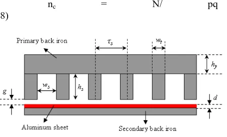
The structure of the single-sided linear induction motor
as well as its slot dimensions are shown in Fig. 1.In this figure g is mechanical clearance. Regarding the magnetic permeability of the aluminum, the mechanical clearance is replaced with magnetic air gap.
The magnetic air gap is defined as:
gm = g + d (1)
where d is the thickness of the secondary sheet. Considering
the concept of current sheet and slotted structure , the magnetic air-gap will increase to effective
air-gap which is given by [15]:
ge = kc gm (2)
In the above equation, c k is Carter's coefficient which is given by:
k =τs/ (τs –γgm)
(3)
where s τ is the slot pitch and is equal to:
τs=τ /mq (4)
W is the slot width which is calculated by:
Ws =τs− wt (5)
Wt is the tooth width. The primary slot depth can be simply calculated by the following equation(see in fig.)
hs = As/ ws (6)
where s A is the cross-sectional area of the primary slot which is given by:
As = ncAw/ Ffill (7)
In the above equation, Aw is the cross-sectional area of the conductor,l Ffill is fill factor of the slot and nc is the number of conductors per slot which is equal to:
nc = N/ pq (8)
Fig7: Dimension dia. For LIM.
where N is the number of turns per phase. Number of turns per coil, ncoil can be calculated using nc . For single layer
winding nc = ncoil .
Phase input
voltage, v
440 Slot depth, mm 52
Supply frequency, Hz
50 Aluminum
thickness, mm
2
Pole pairs 4 Air Gap, mm 0.5
Slots/pole/ phase
2 Number of
turns/phase
818
Tooth width,
mm
5 Motor length, mm 300
Slot width, mm 5
CONCLUSION
Thus, in our project, the linear induction motor was developed to use as a conveyer in various industries. It is used for smooth transmission, high speed, high accuracy and precision is required. Such as space centers, DRDO where high accuracy is required. This project gives idea regarding to use LIM where conventional induction motor used for linear motion drives application.
REFERENCES
1. Nasar, S.A. and Boldea, I., Linear Electric Motors, Prentice-Hall, Inc., Englewood Cliffs, New Jersey, 1987. 2. S.A.Nasar and I.Boldea, Linear motion Electric Machines,
John Wiley and Sons, New York 1976.
3. Boldea, I. and Nasar, S.A., Linear Motion Electromagnetic systems, John Wiley & Sons, Inc., New York, 1985.