DESIGN AND ANALYSIS OF THE HYDRAULIC ARM FOR MOUNTING ON A
LIGHT GOODS VEHICLE
Ing. Blatnický M. PhD.1, Ing. Dižo J. PhD.1, Assoc. prof. Ing. Dalibor Barta, PhD.1
Faculty of Mechanical Engineering – University of Žilina, Slovak Republic1 miroslav.blatnicky@fstroj.uniza.sk, jan.dizo@fstroj.uniza.sk, dalibor.barta@fstroj.uniza.sk
Abstract: This paper is focused on numerical analysis of a hydraulic arm for use on a light goods vehicle. The designed arm is used for loading and manipulation with load up to 300 kg. Its load capacity depends on the light goods vehicle to be placed on. Great operability of this mechanism predetermines its wide application, e.g. in construction, transport, business etc. Firstly, analytical calculations of the forces, moments and reactions are introduced. Further, locations and values of the maximum stress in the structure of the designed hydraulic arm are calculated using the FEM software. These results determine the relevant data necessary for correct design functioning of the machine. After carrying out all the analyses and calculations we will be able to determine the safe use of the designed handling machine and put it into operation.
Keywords: HYDRAULIC ARM, FINITE ELEMENT METHOD, CALCULATION, COMPUTER SIMULATION
1. Introduction
An important role of engineers is to analyse the existing and newly-designed working processes in order to find an optimal way of executing the given operation. The best working process is generally considered the one that minimises the cost of performance, which can be achieved by mechanisation.
Mechanisation is an important means of increasing productivity, quality and production competitiveness. Successful introduction of mechanisation requires knowledge and understanding of physical dependencies of executed operations. Operations are executed by transfer of mechanical, electrical, pneumatic or hydraulic energy.
The aim of this paper is to achieve by analytical dimensional calculation needed dimensions of the middle part of the arm in fig. 1 (needed areas of section) and so to design lifting rotary arm, which will be placed on the pick-up automobile trailer.
After specifying of the dimensions will be possible to create the construction in CAD programme and subsequently by importing of a model into FEM programme verify the real values of stress in designed construction, already with the values, which are not at disposal at preliminary design (E.g. own mass of the construction).
2. Process of a hydraulic arm geometry design
Every transport and handling machine consists of three main parts:
− steel structure,
− driving mechanisms, and
− other parts (e.g. cab, steps, etc.).
The aim of this work is to design and analyse the middle part of a hydraulic arm steel structure to be mounted on a particular light goods vehicle (Fig. 1). The whole mechanism consists of three parts of steel structure. The advantage of this solution is that the operator needs driving license only for vehicles with total mass up to 3500 kg.
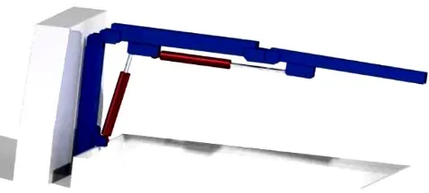
Fig. 1 Pick-up platform for mounting the designed hydraulic arm
2.1. Analysis of forces, moments and reaction on a
hydraulic arm using the principle of superposition
Such a means of mechanisation utilisable not only in transport is the designed hydraulic arm, which significantly simplifies manipulation with great operativeness. With the requirement of minimum production costs we reach the most gainful output/costs ratio.
In this chapter are introduced calculations of forces and moments in joints in the entire structure. Results are necessary for cross sections design of hydraulic arm parts and also were used as the boundary conditions in the FE analysis.
Designed lengths of individual parts, resulting from construction of hydraulic cylinders in Figure 2, are as follows: c1 =
1150 mm, c2 = 1150 mm, c3 = 1180 mm, e1 = e2 = e3 = 75 mm, a1 =
a2 = 210 mm, b1 = 774 mm.
We consider the whole structure as mechanism with one degree of freedom. For solution of the greatest force effects the functional calculation was performed in the most efficient position of a load (Fig. 2). In this step we also obtain the needed forces of hydraulic cylinders for the equilibrium.
Fig. 2 Free diagram of the designed hydraulic arm
In the calculation we start form three basic equilibrium equations:
� 𝐹𝑖𝑥= 0, (1)
� 𝐹𝑖𝑦= 0, (2)
Firstly, forces and reactions in the first part of the hydraulic arm are given (Fig. 3):
� 𝐹𝑖𝑥= 0 ,⟹ 𝐹𝑉1− 𝑅𝐴𝑥= 0,⟹ 𝑅𝐴𝑥=𝐹𝑉1, (5)
� 𝐹𝑖𝑦 = 0,⟹ 𝑅𝐴𝑦− 𝐹𝑧= 0,⟹ 𝑅𝐴𝑦=𝐹𝑧=𝑚.𝑔 = 300.9,81 = 2 943 𝑁, (6)
� 𝑀𝑖𝐴= 0,⟹ −𝐹𝑧.𝑐1+𝐹𝑉1.𝑒1= 0,⟹ 𝐹𝑉1=𝐹𝑧𝑒.𝑐1 1
=2 943.1 15075 = 45 126 𝑁.
(7)
Calculation of reaction values in the middle part of the hydraulic arm is based on Fig 4.
The angle β we calculate according to eq. (8)
𝛽=𝑡𝑔−1.𝑎2− 𝑒3 𝑏2− 𝑒2=𝑡𝑔−1.
210−75
774−75 = 10,931°. (8)
Then, from equilibrium equations we obtain:
� 𝐹𝑖𝑥= 0 ⟹ 𝑅𝐴𝑥− 𝑅𝐵𝑥+𝐹𝑉2.𝑠𝑖𝑛𝛽 − 𝐹𝑉1= 0 ⟹
𝑅𝐵𝑥=𝑅𝐴𝑥+𝐹𝑉2.𝑠𝑖𝑛𝛽 − 𝐹𝑉1,
(9)
� 𝐹𝑖𝑦= 0,⟹ −𝑅𝐴𝑦− 𝑅𝐵𝑦+𝐹𝑉2.𝑐𝑜𝑠𝛽= 0 ⟹
𝑅𝐵𝑦=𝐹𝑉2.𝑐𝑜𝑠𝛽 − 𝑅𝐴𝑦,
(10)
� 𝑀𝑖𝐵= 0 ⟹ 𝐹𝑉2.𝑎2.𝑐𝑜𝑠𝛽+𝐹𝑉2.𝑒2.𝑠𝑖𝑛𝛽 − 𝑅𝐴𝑦.𝑐2 − 𝐹𝑉1.𝑒1= 0
⟹ 𝐹𝑉2=𝑐𝑜𝑠𝛽𝑅𝐴𝑦..𝑎𝑐2+𝐹𝑉1.𝑒1 2+𝑠𝑖𝑛𝛽.𝑒1 =𝑐𝑜𝑠2 943 . 1 150 + 45 126 . 7510,931°. 210 +𝑠𝑖𝑛10,931°. 75
𝐹𝑉2= 30 710,241 𝑁.
(11)
⟹ 𝑅𝐵𝑥= 45 126 + 30 710,241.𝑠𝑖𝑛10,931°−45 126
= 5 823,482 𝑁, (12)
⟹ 𝑅𝐵𝑦= 30 710,241.𝑐𝑜𝑠10,931°−2 943
= 27 210,042 𝑁. (13)
Finally, calculation of forces and reactions are (Fig. 5):
� 𝐹𝑖𝑥= 0,⟹ 𝑅𝐵𝑥− 𝐹𝑉2.𝑠𝑖𝑛𝛽+𝑅𝐶𝑥= 0⟹ 𝑅𝐶𝑥 =𝐹𝑉2.𝑠𝑖𝑛𝛽 − 𝑅𝐵𝑥
𝑅𝐵𝑥= 30 710,241.𝑠𝑖𝑛10,931°−5 823,482 = 0 𝑁,
(14)
� 𝐹𝑖𝑦= 0,⟹ 𝑅𝐵𝑦− 𝐹𝑉2.𝑐𝑜𝑠𝛽+𝑅𝐶𝑦= 0,⟹ 𝑅𝐶𝑦 =𝐹𝑉2.𝑐𝑜𝑠𝛽 − 𝑅𝐵𝑦
𝑅𝐶𝑦= 30 710,241.𝑐𝑜𝑠10,931°−27 210,042
= 2 943 𝑁,
(15)
� 𝑀𝑖𝐶= 0,⟹ 𝑅𝐵𝑥.𝑐3+𝐹𝑉2.𝑐𝑜𝑠𝛽.𝑒3
− 𝐹𝑉2.𝑠𝑖𝑛𝛽. (𝑐3− 𝑏2)− 𝑀𝑠= 0 𝑀𝑠=𝑅𝐵𝑥.𝑐3+𝐹𝑉2.𝑐𝑜𝑠𝛽.𝑒3− 𝐹𝑉2.𝑠𝑖𝑛𝛽. (𝑐3− 𝑏2)
(16)
𝑀𝑠= 5 823,482 . 1 150 + 30 710,241 .𝑐𝑜𝑠
+ 10,931°. 75
−30 710,241 . 𝑠𝑖𝑛10,931°. (1 150
−774) = 6 768,9 𝑁𝑚.
Fig. 3 Forces and reactions in the first part of the hydraulic arm
Fig. 4 Forces and reactions in the middle part of the hydraulic arm
Fig. 5 Forces and reactions in the third part of the hydraulic arm
Therefore, calculated inner force effects of the mechanism (see Fig. 2) are: Fz = 2943 N, Fv1 = 45,126 N, RAx = 45,126 N, RAy =
2943 N, β = 10.931°, Fv2 = 30,710 N, RBx = 5824 N, RBy = 27,210
N, RCy = 2943 N.
2.2. Choice of material, profile and dimensions of
a hydraulic arm
In production of steel construction a material STN 11 423 was chosen, because of its suitable mechanical properties, guaranteed weldability and relatively low cost. Normalised hot drawn square seamless steel tubes were chosen. Provisionally, it is chosen profile TR4 HR 120x100x6-11 423.0 STN 42 5720.
Fig. 6 Chosen steel profile for the hydraulic arm structure
carried out. The body considering as a beam with exact geometry and load, which value was solved in the previous step.
After defining the cross-section dimensions by analytical calculation, it is possible to build a 3D model of the hydraulic arm in CAD software. In Fig. 7 the three-dimensional model of the middle part of the hydraulic arm is shown.
The whole arm consists of three parts and to simplify the problem, numerical analysis of each part of the arm is made separately.
Further as an example, analytical calculation of the middle part of the hydraulic arm is indicated (Fig. 8). In this section the analytic calculation of the middle part of a hydraulic arm is described. Firstly, it is necessary to perform initial analytical calculation of the hydraulic arm structure. In this point we determine strain behaviour in the middle part of the hydraulic arm. Based on them the required dimensions will be it will be defined. The safety coefficient was chosen k = 1.5 [-].
Fig. 7 3D model of the middle part of the hydraulic arm
Calculation of the bending moment as a dominant loading is carried out by method of virtual cut. The beam is cut as many times as it is divided by outer loading, inner loading and by geometry, i.e. three times (Fig. 8).
In critical section, besides bending stress also tensile stress from normal force FN = 5 824 N acts. The total stress then is (1):
𝜎𝑐=𝑀𝑜𝑚𝑎𝑥𝑊 𝑜 +
𝐹𝑁
𝑆 (1)
𝜎𝑐=𝑀𝑜𝑊𝑚𝑎𝑥 𝑜 +
𝐹𝑁
𝑆 (2)
By solving the equation (1), we get a value of total stress σc =
73.8 MPa. Force from the hydro motor FV1 then loads the critical
section through holder by shear stress parallel with the length of the construction and force from the hydro motor FV2 loads the critical
section through the holder also by shear stress, but perpendicular to the length of the construction.
Fig. 8 Pick-up platform for mounting the designed hydraulic arm
Value of the resultant shear stress is found out from the equation (2):
𝜏𝑠=�𝜏𝑠//2+𝜏𝑠┴2 (3)
The resultant shear stress in the critical section then is τs = 9
MPa. Effective stress in the critical section is calculated according to HMH hypothesis (3):
𝜎𝑅𝐸𝐷=�𝜎𝑐2+ 3.𝜏𝑠2 (4)
Value of the effective stress in a weld reaches by analytical method of calculation σRED = 75,5 MPa. However, value of the
resultant stress will grow because of non-considering of.
3. Analysis of the hydraulic arm using Finite
Element Method
In this chapter, the analysis of the hydraulic arm is carried out using the FEM software.
In the programme, there was input material properties to it (elasticity modulus E = 2.1 x 10¹¹ Pa, density 7 850 kg.m-3,
Poisson’s ratio 0.3). Input boundary conditions and meshed shell construction is shown in Fig. 9. Four nodes tetrahedron elements with density of mesh 4 mm were used at meshing.
Fig. 9 Mesh and boundary conditions in the middle part of the
hydraulic arm
After triggering of the solver it is possible to show results in the post-processor and so von Mises’s stress in the first part and in the middle part of the hydraulic arm (Fig. 10, Fig. 11, Fig. 12, Fig. 13).
Fig. 11 Detail of the critical section in the first part
Fig. 12 Effective von Mises’s stress in the middle part of the hydraulic part
Values as well as place of the maximal stress detected by FEM programme are practically identical with those achieved by analytical calculation. Values of the stress in the critical section may be determined in FEM programme in interval 80 – 86 MPa in comparison with 75.5 MPa from analytical calculation. A detail of the critical section with distribution of the effective stress is shown in fig. 7.
Fig. 13 Detail of distribution of the effective stress in the critical
section
Conclusion
In the presented paper was performed design, analysis and calculation of the hydraulic arm, which was designed for mounting on a light goods vehicle. As a suitable platform for installation this arm the chassis of the off-road vehicle can be used. This equipment of a vehicle improves it operability, makes easier manipulation with loads and reduces the operational time. Although the designed structure causes decreasing the vehicle payload, still the vehicle load is enough.
As the every structure as this hydraulic arm has to be submitted analytical calculation and analyses. Well-defined force effects in the proposed mechanism is a necessary precondition for the safe operation of this device. The next step of the performing of this task is an analytical calculation of the cross-sectional dimension of each arms by using of conventional methods of elasticity and strength of material.
After designing of all dimensions creation of the 3D model was possible in a CAD software (Fig. 14). And then, the CAD model was imported into a FEM software. In this way, we could obtain adequate results of the structure strength, etc. Comparison of these two methods allows to find the overall accuracy of the solution. If unsatisfactory results had been identified, the task we could optimize before the expensive production, which in turn will contribute to the cost saving in the production of this mechanism.
Acknowledgement
This contribution is the result of the project implementation: “Modern methods of teaching of control and diagnostic systems of engine vehicles”, ITMS code 26110230107, supported by the Operational Programme Education.
References
[1] Balaja, J., Broncek, J., Antala, J., Sekeresova, D. 2014. Mechanical Engineering Tables. (In Slovak). Selection Standards.
Slovak Office of Standards, Metrology and Testing, 2014. ISBN 978-80-8130-039-4.
[2] Blatnický, M., Dižo, J.: Analysis of the hydraulic arm for use on light goods vehicle. In: Production management and engineering sciences. - Leiden; London: CRC Press/Balkema; Taylor & Francis Group, 2016. - ISBN 978-1-138-02856-2. - S. 351-354.
[3] Blatnický, M., Dižo, J.: Design and analysis of hydraulic arm of light vehicle. In: Zeszyty naukowe Instytutu Pojazdów : mechanika, ekologia, bezpieczeństwo, mechatronika. - ISSN 1642-347X. - 3 (103) /(2015), s. 5-13.
[4] Blatnický, M., Dižo, J.: Analysis of hydraulic arm of light vehicle. In: TSD: XIV international technical systems degradation conference: Liptovský Mikuláš, 8 - 11 April 2015. - Warszawa: Polskie Naukowo-Techniczne Towarzystwo Exploatacyjne, 2015. - ISBN 978-83-930944-7-9. - S. 169-172.
[5] Galliková, J., Poprocký, R.: Use of EAM systems for effective vehicles maintenance. In: TSD: XIV international technical systems degradation conference : Liptovský Mikuláš, 8 - 11 April 2015. - Warszawa: Polskie Naukowo-Techniczne Towarzystwo Exploatacyjne, 2015. - ISBN 978-83-930944-7-9. - S. 21-24.
Republic. - Žilina: University of Žilina, 2015. - ISBN 978-80-554-1048-7. - S. 58-63.
[7] Harušinec, J., Gerlici, J., Lack, T.: Railway wheel / rail contact stress computation by means of FEM. In: Computational and experimental methods in applied mechanics. - Ústí nad Labem: UJEP, 2012. - ISBN 978-80-7414-377-9. - S. 107-118.